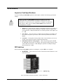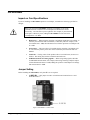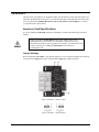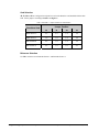
1
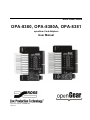
Ross Video Limited
OPA-8380, OPA-8380A, OPA-8381
openGear Card Adapters
User Manual
Ross Part Number: 8380DR-004
Issue: 03
OPA-8380, OPA-8381 • openGear Card Adapters User Manual
•
•
•
Ross Part Number: 8380DR-004
Document Issue: 03
Release Date: May 29, 2009. Printed in Canada.
The information contained in this User Manual is subject to change without notice or obligation.
Copyright
© 2009 Ross Video Limited. All rights reserved.
Contents of this publication may not be reproduced in any form without the written permission of
openGear. Reproduction or reverse engineering of copyrighted software is prohibited.
Notice
The material in this manual is furnished for informational use only. It is subject to change without
notice and should not be construed as a commitment by Ross Video Limited. Ross Video Limited
assumes no responsibility or liability for errors or inaccuracies that may appear in this manual.
Trademarks
•
•
•
•
is a registered trademark of Ross Video Limited.
is a registered trademark of Ross Video Limited.
Ross, ROSS, ROSS ®, and MLE are registered trademarks of Ross Video Limited.
All other product names and any registered and unregistered trademarks mentioned in
this manual are used for identification purposes only and remain the exclusive property
of their respective owners.
Important Regulatory and Safety Notices
Before using this product and any associated equipment, refer to the “Important Safety Instructions”
listed below so as to avoid personnel injury and to prevent product damage.
Products may require specific equipment, and /or installation procedures be carried out to satisfy
certain regulatory compliance requirements. Notices have been included in this publication to call
attention to these Specific requirements.
Symbol Meanings
This symbol on the equipment refers you to important operating and maintenance
(servicing) instructions within the Product Manual Documentation. Failure to heed
this information may present a major risk of damage or injury to persons or
equipment.
Warning
Caution
Notice
The symbol with the word “Warning” within the equipment manual indicates a
potentially hazardous situation, which if not avoided, could result in death or serious
injury.
The symbol with the word “Caution” within the equipment manual indicates a
potentially hazardous situation, which if not avoided, may result in minor or
moderate injury. It may also be used to alert against unsafe practices.
The symbol with the word “Notice” within the equipment manual indicates a
situation, which if not avoided, may result in major or minor equipment damage or a
situation which could place the equipment in a non-compliant operating state.
This symbol is used to alert the user that an electrical or electronic device or
assembly is susceptible to damage from an ESD event.
ESD
Susceptibility
Important Safety Instructions
Caution
This product is intended to be a component product of the openGear 8000 series
frame. Refer to the openGear 8000 series frame User Manual for important safety
instructions regarding the proper installation and safe operation of the frame as well
as it’s component products.
Warning
Certain parts of this equipment namely the power supply area still present a safety
hazard, with the power switch in the OFF position. To avoid electrical shock,
disconnect all A/C power cords from the chassis' rear appliance connectors before
servicing this area.
Warning
Service barriers within this product are intended to protect the operator and service
personnel from hazardous voltages. For continued safety, replace all barriers after
any servicing.
This product contains safety critical parts, which if incorrectly replaced may present
a risk of fire or electrical shock. Components contained within the product’s power
supplies and power supply area, are not intended to be customer serviced and should
be returned to the factory for repair.
To reduce the risk of fire, replacement fuses must be the same type and rating.
Only use attachments/accessories specified by the manufacturer.
EMC Notices
US FCC Part 15
This equipment has been tested and found to comply with the limits for a class A Digital device,
pursuant to part 15 of the FCC Rules. These limits are designed to provide reasonable protection
against harmful interference when the equipment is operated in a commercial environment. This
equipment generates, uses, and can radiate radio frequency energy and, if not installed and used in
accordance with the instruction manual, may cause harmful interference to radio communications.
Operation of this equipment in a residential area is likely to cause harmful interference in which case
users will be required to correct the interference at their own expense.
Changes or modifications to this equipment not expressly approved by Ross Video
Ltd. could void the user’s authority to operate this equipment.
Notice
CANADA
This Class “A” digital apparatus complies with Canadian ICES-003.
Cet appareil numerique de classe “A” est conforme à la norme NMB-003 du Canada.
EUROPE
This equipment is in compliance with the essential requirements and other relevant provisions of CE
Directive 93/68/EEC.
INTERNATIONAL
This equipment has been tested to CISPR 22:1997 along with amendments A1:2000 and A2:2002 and
found to comply with the limits for a Class A Digital device.
This is a Class A product. In domestic environments this product may cause radio
interference in which case the user may have to take adequate measures.
Notice
Maintenance/User Serviceable Parts
Routine maintenance to this openGear product is not required. This product contains no user
serviceable parts. If the module does not appear to be working properly, please contact Technical
Support using the numbers listed under the “Contact Us” section on the last page of this manual. All
RossGear products are covered by a generous 5-year warranty and will be repaired without charge for
materials or labor within this period. See the “Warranty and Repair Policy” section in this manual for
details.
Environmental Information
The equipment that you purchased required the extraction and use of natural resources for its
production. It may contain hazardous substances that could impact health and the environment.
To avoid the potential release of those substances into the environment and to diminish the need for
the extraction of natural resources, Ross Video encourages you to use the appropriate take-back
systems. These systems will reuse or recycle most of the materials from your end-of-life equipment in
an environmentally friendly and health conscious manner.
The crossed-out wheeled bin symbol invites you to use these systems.
If you need more information on the collection, reuse, and recycling systems, please contact your local
or regional waste administration.
You can also contact Ross Video for more information on the environmental performances of our
products.
Contents
Introduction
1-1
In This Chapter .......................................................................................................................1-1
A Word of Thanks....................................................................................................1-1
Overview ..................................................................................................................1-1
Documentation Terms ..............................................................................................1-2
Installing an openGear Card Adapter
2-1
In This Chapter .......................................................................................................................2-1
Static Discharge........................................................................................................2-1
OPA-8380-4 ...........................................................................................................................2-2
Impact on Card Specifications..................................................................................2-2
DIP Switches ............................................................................................................2-2
OPA-8380-9 ...........................................................................................................................2-3
Impact on Card Specifications..................................................................................2-3
DIP Switches ............................................................................................................2-3
OPA-8380A............................................................................................................................2-4
Impact on Card Specifications..................................................................................2-4
Jumper Setting..........................................................................................................2-4
OPA-8381...............................................................................................................................2-5
Impact on Card Specifications..................................................................................2-5
Installing an openGear Card Adapter .....................................................................................2-7
Required Materials ...................................................................................................2-7
Installing an openGear Card Adapter .......................................................................2-7
Removing the openGear Card Adapter.................................................................................2-10
Cable Connections ................................................................................................................2-13
BNC Connections...................................................................................................2-13
Audio Connections for the OPA-8381 ...................................................................2-14
Service Information
3-1
In This Chapter .......................................................................................................................3-1
Troubleshooting Checklist .......................................................................................3-1
Warranty and Repair Policy .....................................................................................3-2
Ordering Information
4-1
openGear Card Adapters and Related Products......................................................................4-1
openGear Card Adapters User Manual (Iss. 03)
Contents • i
ii • Contents
openGear Card Adapters User Manual (Iss. 03)
Introduction
In This Chapter
This chapter contains the following sections:
•
A Word of Thanks
•
Overview
•
Documentation Terms
A Word of Thanks
Congratulations on choosing the openGear Card Adapters OPA-8380-4, OPA-8380-9, OPA-8380A
or the OPA-8381. The openGear Card Adapters are part of a full line of Digital Products within the
openGear Terminal Equipment family of products, backed by Ross Video’s experience in engineering
and design expertise since 1974.
You will be pleased at how easily your new openGear Card Adapters fits into your overall working
environment. Equally pleasing is the product quality, reliability and functionality. Thank you for
joining the group of worldwide satisfied Ross Video customers!
Should you have a question pertaining to the installation or operation of your openGear Card
Adapters, please contact us at the numbers listed on the back cover of this manual. Our technical
support staff is always available for consultation, training, or service.
Overview
The openGear Card Adapters allows for the use of select RossGear cards to be fitted into the openGear
platform. The openGear Card Adapters allow the platform to house cost effective Analog, SD, and
AES solutions for today’s needs while future proofing the platform investment for tomorrow’s needs.
Refer to the document Qualified RossGear Cards for the openGear Card Adapter (8380DR-005)
for a complete list of qualified RossGear cards for your adapter.
openGear Card Adapters User Manual (Iss. 03)
Introduction • 1-1
Documentation Terms
The following terms are used throughout this guide:
1-2 • Introduction
•
“openGear Card Adapters” refers to the OPA-8380-4, OPA-8380-9, OPA-8380A
and OPA-8381 unless otherwise noted.
•
“Frame” refers to the DFR-8300 series frame that houses the openGear Card
Adapters.
•
All references to the DFR-8300 series frames also includes all versions of the 10-slot
(DFR-8310 series) and the 20-slot (DFR-8320 series) frames and any available
options unless otherwise noted.
•
“Operator” and “User” refer to the person who uses the openGear Card Adapters.
•
“Board”, and “Card” refer to the RossGear card itself, including all components
and switches.
•
“System” and “Video system” refer to the mix of interconnected production and
terminal equipment in which the RossGear card operates.
openGear Card Adapters User Manual (Iss. 03)
Installing an openGear Card
Adapter
In This Chapter
This chapter contains the following sections:
•
Static Discharge
•
OPA-8380-4
•
OPA-8380-9
•
OPA-8380A
•
OPA-8381
•
Installing an openGear Card Adapter
•
Removing an openGear Card Adapter
•
Cable Connections
Static Discharge
Whenever handling the openGear Card Adapters and other related equipment, observe all static
discharge precautions as described in the following note:
ESD
Susceptibility
Static discharge can cause serious damage to sensitive semiconductor
devices. Avoid handling circuit boards in high static environments such as
carpeted areas, and when wearing synthetic fiber clothing. Always exercise
proper grounding precautions when working on circuit boards and related
equipment.
openGear Card Adapters User Manual (Iss. 03)
Installing an openGear Card Adapter • 2-1
OPA-8380-4
Impact on Card Specifications
If you are installing an OPA-8380-4 openGear Card Adapter, remember the following specification
change:
Caution
When you connect the OPA-8380-4 openGear Card Adapter to a qualified
RossGear card, the Power Consumption of the RossGear card is doubled due to
power regulation. For example, if your RossGear card requires 3 Watts of
power, adding the OPA-8380-4 increases the Power Consumption to 6 Watts.
DIP Switches
Before installing the OPA-8380-4 openGear Card Adapter, verify that the DIP switches are set as
follows:
•
S2 REF SEL — Ensure this DIP Switch is set to the REF-1 position.
Figure 1. OPA-8380-4 openGear Card Adapter — Position of DIP Switch
2-2 • Installing an openGear Card Adapter
openGear Card Adapters User Manual (Iss. 03)
OPA-8380-9
Impact on Card Specifications
If you are installing an OPA-8380-9 openGear Card Adapter, remember the following specification
changes:
Caution
When you connect the OPA-8380-9 openGear Card Adapter to one of the
qualified RossGear cards, the Power Consumption of the RossGear card is
increased by 1.25 times due to power regulation. For example, if your RossGear
card requires 3 Watts of power, adding the OPA-8380-9 increases the Power
Consumption to 3.75 Watts.
•
Return Loss —When using the openGear Card Adapter the Return Loss number, as
stated in your RossGear card User Manual, is reduced by 3dB. For example, if the
user manual states -18dB, then the Return Loss with the openGear Card Adapter will
be -15dB.
•
Power Draw — The power draw of a module plus the openGear Card Adapter will
be 1.25 times the positive power draw value as stated in your RossGear card User
Manual.
•
Com-Link — If using a Ross Video product with a Com-Link feature, do not set to
AUX B. This setting may interfere with the Frame Reference.
•
SNR Measurements for Analog Signals — When using analog signals, add 1dB
for 5MHz BW measurements. For example, when using an analog composite output
with an SNR measurement of -59dB, adding the openGear Card Adapter changes
that measurement to -58dB.
DIP Switches
Before installing the OPA-8380-9 openGear Card Adapter, verify that S2 is set as required:
•
S2 REF SEL — This switch can be used to switch between Frame Reference 1 and
Frame Reference 2.
Figure 2. OPA-8380-9 openGear Card Adapter — Position of DIP Switch
openGear Card Adapters User Manual (Iss. 03)
Installing an openGear Card Adapter • 2-3
OPA-8380A
Impact on Card Specifications
If you are installing an OPA-8380A openGear Card Adapter, remember the following specification
changes:
Caution
When you connect the OPA-8380A openGear Card Adapter to one of the
qualified RossGear cards, the Power Consumption of the RossGear card is
increased by 1.25 times due to power regulation. For example, if your RossGear
card requires 3 Watts of power, adding the OPA-8380A increases the Power
Consumption to 3.75 Watts.
•
Return Loss — When using the openGear Card Adapter the Return Loss number, as
stated in your RossGear card User Manual, is reduced by 3dB. For example, if the
user manual states -18dB, then the Return Loss with the openGear Card Adapter will
be -15dB.
•
Power Draw — The power draw of a module plus the openGear Card Adapter will
be 1.25 times the positive power draw value as stated in your RossGear card User
Manual.
•
Com-Link — If using a Ross Video product with a Com-Link feature, do not set to
AUX B. This setting may interfere with the Frame Reference.
•
SNR Measurements for Analog Signals — When using analog signals, add 1dB
for 5MHz BW measurements. For example, when using an analog composite output
with an SNR measurement of -59dB, adding the openGear Card Adapter will change
that measurement to -58dB.
Jumper Setting
Before installing the OPA-8380A, verify that J1 is set as required:
•
J1 REF SEL — This jumper is used to switch between Frame Reference 1 and
Frame Reference 2.
Figure 3. OPA-8380A— Location of JP1
2-4 • Installing an openGear Card Adapter
openGear Card Adapters User Manual (Iss. 03)
OPA-8381
The OPA-8381 Card Adapter was designed to enable specific RossGear cards with audio inputs to be
installed in the DFR-8300 series frames. For a list of the RossGear cards qualified for the OPA-8381,
refer to the document “Qualified RossGear Cards for the openGear Card Adapters” or contact
your openGear sales representative.
Impact on Card Specifications
If you are installing an OPA-8381 openGear Card Adapter, remember the following specification
changes:
Caution
When you connect the OPA-8381 openGear Card Adapter to one of the
qualified RossGear cards, the Power Consumption of the RossGear card is
increased by 0.4W due to power regulation. For example, if your RossGear card
requires 2.6W of power, adding the OPA-8381 increases the Power
Consumption to 3W.
Jumper Settings
Before installing the OPA-8381, verify that the jumpers are set as required according to the following
sections. Refer to Figure 4 for jumper locations and to Figure 5 for jumper positions.
Figure 4. OPA-8381 — Jumper Locations
Figure 5. OPA-8381 — Jumper Positions
openGear Card Adapters User Manual (Iss. 03)
Installing an openGear Card Adapter • 2-5
Card Selection
J2, J3, J4 and J5 are configured in conjunction to select the RossGear card installed with the OPA8381. Set the jumpers according to Table 1 and Figure 5.
Table 1. OPA-8381 — Jumper Positions for Card Selection
RossGear Card
Jumper Position
J2
J3
J4
J5
MUX-8552A-C
2+3
2+3
1+2
1+2
DMX-8554A-C
1+2
1+2
1+2
1+2
ADL-8520A-B
2+3
1+2
1+2
1+2
ADL-8520A-A
2+3
1+2
2+3
2+3
Reference Selection
Use J6 to switch between Frame Reference 1 and Frame Reference 2.
2-6 • Installing an openGear Card Adapter
openGear Card Adapters User Manual (Iss. 03)
Installing an openGear Card Adapter
This section outlines how to install the openGear Card Adapter onto a qualified RossGear card.
Installing the openGear Adapter Retaining Clip (8310FR-421) secures the RossGear card to the
openGear Card Adapter, enabling you to easily insert and extract the cards from the openGear frame.
The procedure is identical for each qualified RossGear card and openGear Card Adapter, except where
noted within the procedures.
You cannot install an openGear Card Adapter into slot 10 of a DFR-8310 frame.
Attempting to insert an openGear Card Adapter into slot 10 may damage the
RossGear card, the FINC card, or both.
Caution
Required Materials
To perform this installation, you require the following components and equipment:
•
a qualified RossGear card
•
an openGear Card Adapter
•
an openGear Adapter Retaining Clip (8310FR-421)
If any required materials are missing, contact your sales representative or Ross Video directly.
Installing an openGear Card Adapter
Use the following procedure to install an openGear Card Adapter to a qualified RossGear card:
1.
Ensure your RossGear card is one of the qualified model numbers for the openGear Card
Adapter. The model number is silk-screened, or applied as a label, onto the face of your
RossGear card and onto the card ejector (for current issue RossGear cards).
2.
Place the cards on a clean and static-free surface, ensuring that:
•
the RossGear card is on your right and the openGear Card Adapter is on your
left.
•
the cards are component-side down. The Ross and openGear logos will be face
down on the surface. Refer to Figure 6 for details.
Figure 6. Positioning the Cards
openGear Card Adapters User Manual (Iss. 03)
Installing an openGear Card Adapter • 2-7
3.
Grip the openGear Adapter Retaining Clip, with the hooks facing down, and position it
between the connector and the card-edge of the RossGear Card. Refer to Figures 7 and 8
for details.
Figure 7. Positioning the openGear Adapter Retaining Clip — Top View
Figure 8. Positioning the openGear Adapter Retaining Clip — Side View
4.
Ensure the openGear Adapter Retaining Clip is upright and perpendicular to the
RossGear card. Refer to Figure 8 or details.
5.
Mate the connector of the RossGear card to the connector on the openGear Card Adapter.
The connector of the openGear Card Adapter fits over the openGear Adapter Retaining
Clip. Refer to Figure 8 for details.
Figure 8. Mating the RossGear Card with the openGear Card Adapter
Note
Ensure the openGear Card Adapter mates securely to the RossGear card.
2-8 • Installing an openGear Card Adapter
openGear Card Adapters User Manual (Iss. 03)
6.
Using your thumb and index finger, apply downward pressure to insert the clip arms into
the slots of the openGear Card Adapter. Refer to Figures 9 and 10 for details.
Figure 9. Inserting the openGear Adapter Retaining Clip – Side View
Figure 10. Position of the Inserted openGear Adapter Retaining Clip – Top View
7.
Note
Verify that the openGear Adapter Retaining Clip is secure as follows:
•
flip the cards over so that the silkscreen logos face you. The openGear Card
Adapter is on the left.
•
ensure the clip arms are locked into position in the slots on the openGear Card
Adapter card-edge. The ends of the clip arms will be visible and secure in the
slots.
If the openGear Adapter Retaining Clip is not secure, ensure the slots or the clip
sides were not bent by removing the clip according to the instructions in the
section “Removing the openGear Card Adapter” in this manual. Then gently
correct the misaligned clip components and repeat the installation procedure.
This completes the procedure to install openGear Card Adapter to a qualified RossGear card.
openGear Card Adapters User Manual (Iss. 03)
Installing an openGear Card Adapter • 2-9
Removing the openGear Card Adapter
Use the following procedure to remove an openGear Card Adapter:
1.
Place the attached cards on a clean and static-free surface, ensuring the RossGear card is
on your right and the openGear Card Adapter is on your left.
2.
Flip the cards over so that the silkscreen logos face the surface. The openGear Card
Adapter will still be on your left. Refer to Figure 11 for orientation.
Figure 11. openGear Card Adapter and RossGear Card Orientation
3.
Hold the openGear Card Adapter steady, and pinch the openGear Adapter Retaining Clip
using the thumb and index finger as shown by the arrows in Figure 12.
Figure 12. Positioning the openGear Card Adapter and Retaining Clip — Top View
2-10 • Installing an openGear Card Adapter
openGear Card Adapters User Manual (Iss. 03)
4.
Gently pinch and tilt the clip arms away from the openGear Card Adapter until they are
perpendicular to the RossGear card. Refer to Figures 13 and 14 for details.
Figure 13. Pulling Upwards on the openGear Adapter Retaining Clip — Top View
Figure 14. Positioning the openGear Adapter Retaining Clip – Side View
5.
Grasp the RossGear card in your right hand, and the openGear Card Adapter in your left
hand.
6.
Gently pull the two cards apart, taking care not to twist to pry the openGear Card
Adapter connector as you disengage the pins. Refer to Figure 15 for details.
Figure 15. Disengaging the Cards
openGear Card Adapters User Manual (Iss. 03)
Installing an openGear Card Adapter • 2-11
7.
Remove the openGear Adapter Retaining Clip from its position between the connector
and the card-edge of the RossGear Card and set aside. Refer to Figure 16 for details.
Figure 16. Disengaging the openGear Adapter Retaining Clip
This completes the procedure to remove an openGear Card Adapter.
2-12 • Installing an openGear Card Adapter
openGear Card Adapters User Manual (Iss. 03)
Cable Connections
This section provides information for connecting cables to the installed Rear Modules on the DFR8300 series frame backplane.
BNC Connections
Connect the input and output cables according to the table located on the front of the openGear Card
Adapter and the information in this section. Refer to Figure 17 and Table 2 for information on the pin
to pin conversion when installing a Qualified RossGear Card into the DFR-8300 series frame.
Figure 17. Pin to Pin Conversion for Qualified Cards into the DFR-8300 Series Frames
Refer to Table 2, and the BNC Label that accompanied your RossGear card, to connect cables to a
qualified RossGear Card installed in an openGear rear module. For example, connect the required
input cable to BNC 2 on the rear module.
Table 2. RossGear to openGear BNC Conversion
RossGear
BNC Connection
openGear
BNC Connection
IN
BNC 2
BNC 1
BNC 4
BNC 2
BNC 3
BNC 3
BNC 6
BNC 4
BNC 5
BNC 5
BNC 8
BNC 6
BNC 7
BNC 7
BNC 10
BNC 8
BNC 9
openGear Card Adapters User Manual (Iss. 03)
Installing an openGear Card Adapter • 2-13
Audio Connections for the OPA-8381
Connect the input and output cables according to the silkscreen table on the back of the openGear Card
Adapter and the information in this section. Refer to the following figures for information on the pin to
pin conversion when installing an MUX-8552A-A, DMX-8554A-C, ADL-8520A-B, or an ADL8520A-A into the DFR-8300 series frame using the OPA-8381 Card Adapter.
Figure 18. Cable Connections for the MUX-8552A-C
Figure 19. Cable Connections for the DMX-8554A-C
Figure 20. Cable Connections for the ADL-8520A-B
Figure 21. Cable Connections for the ADL-8520A-A
2-14 • Installing an openGear Card Adapter
openGear Card Adapters User Manual (Iss. 03)
Service Information
In This Chapter
This chapter contains the following sections:
•
Troubleshooting Checklist
•
Warranty and Repair Policy
Troubleshooting Checklist
Routine maintenance to this openGear product is not required. In the event of problems with your
qualified RossGear cards, the following basic troubleshooting checklist may help identify the source
of the problem. If the card still does not appear to be working properly after checking all possible
causes, please contact your openGear products distributor, or the openGear Technical Support
department at the numbers listed under the “Contact Us” section at the end of this manual.
1.
Visual Review – Performing a quick visual check may reveal many problems, such
as connectors not properly seated or loose cables. Check the module, the frame, and
any associated peripheral equipment for signs of trouble.
2.
Power Check – Check the power indicator LED on the distribution frame front
panel for the presence of power. If the power LED is not illuminated, verify that the
power cable is connected to a power source and that power is available at the power
main. Confirm that the power supplies are fully seated in their slots. If the power
LED is still not illuminated, replace the power supply with one that is verified to
work.
3.
Reseat the Card in the Frame – Eject the card and reinsert it in the frame.
4.
Check Control Settings – Refer to the Installation and Operation sections of the
card’s User Manual and verify all user-adjustable component settings.
5.
Input Signal Status – Verify that source equipment is operating correctly and that a
valid signal is being supplied.
6.
Output Signal Path – Verify that destination equipment is operating correctly and
receiving a valid signal.
7.
Module Exchange – Exchanging a suspect module with a module that is known to
be working correctly is an efficient method for localizing problems to individual
modules.
openGear Card Adapters User Manual (Iss. 03)
Service Information • 3-1
Warranty and Repair Policy
The openGear Card Adapter is warranted to be free of any defect with respect to performance, quality,
reliability, and workmanship for a period of FIVE (5) years from the date of shipment from our
factory. In the event that your openGear Card Adapter proves to be defective in any way during this
warranty period, Ross Video Limited reserves the right to repair or replace this piece of equipment
with a unit of equal or superior performance characteristics.
Should you find that this openGear Card Adapter has failed after your warranty period has expired, we
will repair your defective product should suitable replacement components be available. You, the
owner, will bear any labor and/or part costs incurred in the repair or refurbishment of said equipment
beyond the FIVE (5) year warranty period.
In no event shall Ross Video Limited be liable for direct, indirect, special, incidental, or consequential
damages (including loss of profits) incurred by the use of this product. Implied warranties are
expressly limited to the duration of this warranty.
This openGear Card Adapter User Manual provides all pertinent information for the safe installation
and operation of your openGear Product. Ross Video policy dictates that all repairs to the openGear
Card Adapters are to be conducted only by an authorized Ross Video Limited factory representative.
Therefore, any unauthorized attempt to repair this product, by anyone other than an authorized Ross
Video Limited factory representative, will automatically void the warranty. Please contact Ross Video
Technical Support for more information.
In Case of Problems
Should any problem arise with your openGear Card Adapter, please contact the Ross Video Technical
Support Department. (Contact information is supplied at the end of this publication.)
A Return Material Authorization number (RMA) will be issued to you, as well as specific shipping
instructions, should you wish our factory to repair your openGear Card Adapter. If required, a
temporary replacement module will be made available at a nominal charge. Any shipping costs
incurred will be the responsibility of you, the customer. All products shipped to you from Ross Video
Limited will be shipped collect.
The Ross Video Technical Support Department will continue to provide advice on any product
manufactured by Ross Video Limited, beyond the warranty period without charge, for the life of the
equipment.
3-2 • Service Information
openGear Card Adapters User Manual (Iss. 03)
Ordering Information
openGear Card Adapters and Related Products
This chapter contains ordering information for the openGear Card Adapters and related products.
Standard Equipment
•
OPA-8380-4 openGear Card Adapter
•
OPA-8380-9 openGear Card Adapter
•
OPA-8380A openGear Card Adapter
•
OPA-8381 openGear Card Adapter
•
8310FR-421 openGear Adapter Retaining Clip
•
8380DR-004 openGear Card Adapter User Manual
Optional Equipment
•
8380DR-004 additional openGear Card Adapter User Manual
•
8380DR-005 Qualified RossGear Cards for the openGear Card Adapter Document
•
RM-8300-B Rear Panel that includes ten 10-BNC rear modules for installation into
DFR-8310-C frames
•
DFR-8310-C Digital Products Frame and Power Supply with Cooling Fans
(2RU, holds 10 cards)
•
DFR-8320-CNS Digital Products Frame with Power Supply, Cooling Fans,
Network Controller Card, COMM I/O Module, and SNMP-8310 (2RU, holds up to
20 cards)
Your openGear Card Adapters are a part of the openGear family of products. Ross Video offers a full
line of openGear terminal equipment including distribution, conversion, monitoring, synchronizers,
encoders, decoders, AES, keyers, switches, as well as analog audio and video products.
openGear Card Adapters User Manual (Iss. 03)
Ordering Information • 4-1
Contact Us
Contact our friendly and professional support representatives for the following:
•
Name and address of your local dealer
•
Product information and pricing
•
Technical support
•
Upcoming trade show information
PHONE
E-MAIL
POSTAL
SERVICE
General Business Office
and Technical Support
613 • 652 • 4886
After Hours Support
613 • 349 • 0006
Fax
613 • 652 • 4425
General Information
[email protected]
Technical Support
[email protected]
Ross Video Limited
8 John Street,
Iroquois, Ontario, Canada
K0E 1K0
Ross Video Incorporated
P.O. Box 880,
Ogdensburg, New York, USA
13669-0880
Visit Us
Please visit us at our website for:
•
Company information
•
Related products and full product lines
•
On-line catalog
•
Trade show information
•
News
•
Testimonials