1
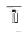
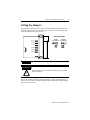
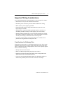
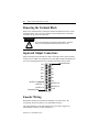
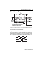
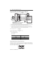
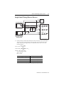
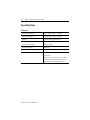
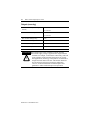
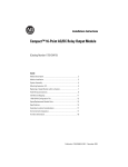
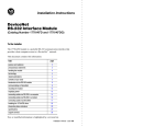
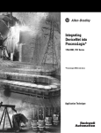
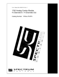
Installation Instructions Multi-Channel High-Speed Counter 1746-HSCE2 Inside For More Information ..................................................................2 Compliance to European Union Directives .................................3 Hazardous Location Considerations ............................................4 Environnements dangereux..........................................................4 Hardware Features .......................................................................5 LEDs ............................................................................................6 Prevent Electrostatic Discharge ...................................................6 Setting the Jumpers ......................................................................7 Installing the Module ...................................................................8 Important Wiring Considerations.................................................9 Removing the Terminal Block ...................................................10 Input and Output Connections ...................................................10 Encoder Wiring ..........................................................................10 Electronic Protection..................................................................14 Specifications.............................................................................16 Publication 1746-IN002A-US-P 2 Multi-Channel High-Speed Counter For More Information As part of our effort to preserve, protect, and improve our environment, Allen-Bradley is reducing the amount of paper we use. Less paper means more options for you. In addition to traditional printed publications and CD-ROM versions, we now offer on-line materials with the most up-to-date information you can get. We recommend that you read the related publications listed below before starting up your control system. Related Publications For Refer to this Document Pub. No. A more detailed description on how to install, configure, and operate your multi-channel high speed counter. Multi-channel High Speed Counter User Manual 1746-6.20 A detailed description on how to install and use your modular SLC 500™ system SLC 500 Modular Hardware Style Installation and Operation Manual 1747-6.2 A reference manual that contains status file data and instruction set information for SLC 500 processors. SLC 500™ and MicroLogix™ 1000 Instruction Set Reference Manual 1747-6.15 How to Get More Information If you would like a manual, you can: • download a free electronic version from the internet at www.theautomationbookstore.com • purchase a printed manual by: – contacting your local distributor or Rockwell Automation representative – visiting www.theautomationbookstore.com and placing your order – calling 1.800.963.9548 (USA/Canada) or 001.330.725.1574 (Outside USA/Canada) Publication 1746-IN002A-US-P Multi-Channel High-Speed Counter 3 Compliance to European Union Directives If this product has the CE mark, it is approved for installation within the European Union and EEA regions. It has been designed and tested to meet the following directives. EMC Directive This product is tested to meet Council Directive 89/336/EEC Electromagnetic Compatibility (EMC) and the following standards, in whole or in part, documented in a technical construction file: • EN 50081-2 EMC – Generic Emission Standard, Part 2 – Industrial Environment • EN 50082-2 EMC – Generic Immunity Standard, Part 2 – Industrial Environment This product is intended for use in an industrial environment. Low Voltage Directive This product is tested to meet Council Directive 73/23/EEC Low Voltage, by applying the safety requirements of EN 61131-2 Programmable Controllers, Part 2 – Equipment Requirements and Tests. For specific information required by EN61131-2, see the appropriate sections in this publication, as well as the following Allen-Bradley publications: • Industrial Automation, Wiring and Grounding Guidelines for Noise Immunity, publication 1770-4.1 • Automation Systems Catalog, publication B111 Publication 1746-IN002A-US-P 4 Multi-Channel High-Speed Counter Hazardous Location Considerations This equipment is suitable for use in Class I, Division 2, Groups A, B, C, D, or non-hazardous locations only. The following ATTENTION statement applies to use in hazardous locations. EXPLOSION HAZARD WARNING ! • Substitution of components may impair suitability for Class I, Division 2. • Do not replace components or disconnect equipment unless power has been switched off, and the area is known to be non-hazardous. • Do not connect or disconnect connectors or operate switches while circuit is live unless the area is known to be non-hazardous. • All wiring must comply with N.E.C. article 501-4(b). Environnements dangereux Cet équipement est conçu pour être utilisé dans des environnements de Classe 1, Division 2, Groupes A, B, C, D, ou non dangereux. La mise en garde suivante s’applique à une utilisation dans des environnements dangereux. DANGER D’EXPLOSION MISE EN ! • La substitution de composants peut rendre cet équipement impropre à une utilisation en environnement de Classe 1, Division 2. • Couper le courant ou s’assurer que l’emplacement est désigné non dangereux avant de remplacer les composants. • Couper l’alimentation ou s’assurer que l’environnement est classé non dangereux avant de brancher ou débrancher des connecteurs ou de faire fonctionner des commutateurs. Publication 1746-IN002A-US-P Multi-Channel High-Speed Counter 5 Hardware Features The module’s hardware features are illustrated below. COUNTER OUTPUT STATUS Input Status LEDs 0 1 2 A1 B1 Z1 RUN A2 B2 Z2 FLT INPUT STATUS 3 Output Status LEDs Running Status LED Fault Status LED HSCE2 Input and Output Terminals Publication 1746-IN002A-US-P 6 Multi-Channel High-Speed Counter LEDs The front panel has a total of twelve indicator LEDs. LED Color Indicates 0 OUT Green ON/OFF status of real output 1 OUT Green ON/OFF status of real output 2 OUT Green ON/OFF status of real output 3 OUT Green ON/OFF status of real output RUN Green Running status of the module FLT Red Steady on: Module fault Flashing: Output overcurrent A1 Yellow ON/OFF status of input A1 A2 Yellow ON/OFF status of input A2 B1 Yellow ON/OFF status of input B1 B2 Yellow ON/OFF status of input B2 Z1 Yellow ON/OFF status of input Z1 Z2 Yellow ON/OFF status of input Z2 Prevent Electrostatic Discharge ATTENTION ! Static discharges may cause permanent damage to the module. Follow these guidelines when you handle the module: • Touch a grounded object to discharge static potential. • Wear an approved wrist strap grounding device. • Handle module by plastic case only. Avoid contact between module circuits and any surface which can hold an electrostatic charge. • If available, use a static-safe work station. Publication 1746-IN002A-US-P Multi-Channel High-Speed Counter 7 Setting the Jumpers Six jumpers are located in a row on the side of the module. Use the jumpers to select the input voltage for each of the inputs A1, B1, Z1, A2, B2, and Z2. The settings are shown in the figure below. Jumper Settings JP1 (A1 ) 5V dc 4.2-12V dc 24V dc 10-30V dc JP2 (B1) JP3 (Z1) JP4 (A2) (default) JP5 (B2) JP6 (Z2) IMPORTANT For a 12V dc encoder signal, use the 24V dc jumper setting. ATTENTION ! If jumpers are not set to match the encoder type, the module may be damaged. The 5V dc settings respond to inputs with a active or high settings between 4.2 and 12 volts. The 24V dc settings respond to inputs with active or high settings between 10 and 30 volts. Publication 1746-IN002A-US-P 8 Multi-Channel High-Speed Counter Installing the Module ATTENTION ! Disconnect power before attempting to install, remove, or wire the module. 1. Make sure your SLC power supply has adequate reserve current capacity. The module requires 250 mA at +5V dc. 2. Align the full-sized circuit board with the chassis card guide as shown below. The first slot of the first chassis is reserved for the processor. 3. Slide the module into the chassis until the top and bottom latches catch. To remove the module, press the release clips at the top and bottom of the module and slide it out. 4. Cover all unused card slots with the Card Slot Filler, catalog number 1746-N2. Publication 1746-IN002A-US-P Multi-Channel High-Speed Counter 9 Important Wiring Considerations Use the following guidelines when planning the system wiring for the module: • Install the SLC 500 system in a NEMA-rated enclosure. • Disconnect power to the SLC processor and the module before wiring. • Make sure the system is properly grounded. • Group this module and low-voltage DC modules away from AC I/O or high-voltage DC modules. • Shielded cable is required for high-speed input signals A, B, and Z. Use individually shielded, twisted pair cable lengths up to 300 m (1000 ft.). • Shields should be grounded only at one end. Ground the shield wire outside the module at the chassis mounting screw. Connect the shield at the encoder end only if the housing is isolated from the motor and ground. • If you have a junction in the cable, treat the shields as a conductor at all junctions. Do not ground them to the junction box. Considerations for Reducing Noise In high noise environments, the 1746-HSCE2 inputs may accept “false” pulses, particularly when using low frequency input signals with slowly sloping pulse edges. To minimize the effects of high frequency noise on low frequency signals, the user can do the following: • Identify and remove noise sources. • Route 1746-HSCE2 input cabling away from noise sources. • Install low pass filters on input signals. Filter values are dependent on the application and can be determined empirically. • Use devices which output differential signals, like differential encoders, to minimize the possibility that a noise source will cause a false input. Publication 1746-IN002A-US-P 10 Multi-Channel High-Speed Counter Removing the Terminal Block Remove the terminal block by turning the slotted terminal block release screws counterclockwise. The screws are attached to the terminal block, so the block will follow as the screws are turned out. ATTENTION ! To avoid cracking the removable terminal block, alternate removal of the slotted terminal block release screws. Input and Output Connections Input and output wiring terminals are shown in the figure below. Each terminal accepts two #14 AWG wires. Tighten screws only tight enough to immobilize the wire. The torque applied to the screw should not exceed 0.9 Nm (8 in-lb). Release Screw A1+ B1+ A1B1- Z1+ A2+ B2+ Z2+ OUTPUT COMMON OUTPUT 1 OUTPUT 3 Release Screw Z1A2B2Z2OUTPUT 0 OUTPUT 2 +Vdc Encoder Wiring Differential encoders provide the best immunity to electrical noise. We recommend, whenever possible, to use differential encoders. The wiring diagrams on the following pages are provided to support the Allen-Bradley encoders you may already own. Publication 1746-IN002A-US-P Multi-Channel High-Speed Counter 11 Differential Encoder Wiring Cable(1) +VDC VS GND COM A A(+) A A(–) B B(+) B B(–) Z Z(+) Z Z(–) Allen-Bradley 845H Series differential encoder Power Suppl Shield Earth shield/housing Connect only if housing is electronically isolated from the motor and ground. (1) Module Inputs Refer to your encoder manual for proper cable type. The type of cable used should be twisted pair, individually shielded cable with a maximum length of 300m (1000 ft.). Differential Encoder Output Waveforms The figure below shows the different encoder output waveforms. If your encoder matches these waveforms, the encoder signals can be directly connected to the associated screw terminals on the module. For example, the A lead from the encoder is connected to the module’s A+ screw. If your encoder does not match these waveforms, some wiring modifications may be necessary. See the user’s manual for your encoder. A A B B Z Z Publication 1746-IN002A-US-P 12 Multi-Channel High-Speed Counter Single-Ended Encoder Wiring (Open Collector) cable(1) VS +VDC GND COM R Power Supply (2) A(+) A A(–) B Allen-Bradley 845H Series single-ended encoder B(+) B(–) Z(+) Z Z(–) shield shield/housing Connect only if housing is electronically isolated from the motor and ground. Earth Module Inputs (1) Refer to your encoder manual for proper cable type. The type of cable used should be twisted pair, individually shielded cable with a maximum length of 300m (1000 ft.). (2) External resistors are needed if not internal to the encoder. The pull-up resistor (R) value depends on the power supply value. The table below shows resistor values for typical supply voltages. To calculate the resistor value, use one of the following formulas: ( Vcc – Vmin ) For 5V dc jumper position: R = ---------------------------------Imin ( Vcc – Vmin ) For 24V dc jumper position:R = ---------------------------------– 1KΩ Imin where:R = pull-up resistor value Vcc = power supply voltage Vmin = 4.2 V dc Imin = 6.3 mA Power Supply Voltage (Vcc) 5V dc 12V dc 24V dc (1) Pull-up Resistor Value (R)(1) 127 Ω 238 Ω 2140 Ω Resistance values may change, depending upon your application. Single-Ended Encoder Output Waveforms The figure below shows the single-ended encoder output waveforms. When the waveform is low, the encoder output transistor is on. When the waveform is high, the encoder output transistor is off. A B Z Publication 1746-IN002A-US-P Multi-Channel High-Speed Counter 13 Single-Ended Wiring (Discrete Devices) +VDC COM Power Supply proximity sensor VS A(+) OUT A(–) COM solid-state switch VS OUT B(+) COM B(–) VS OUT R (1) Z(+) COM Z(–) photoelectric sensor with open collector sinking output Module Inputs (1) External resistors are needed if not internal to the sensor. Check your sensor’s documentation. The pull-up resistor (R) value depends on the power supply value. The table below shows resistor values for typical supply voltages. To calculate the resistor value, use one of the following formulas: Vcc – Vmin ) For 5V dc: R = (-----------------------------------Imin Vcc – Vmin ) For 24V dc:R = (-----------------------------------– 1 K Ω Imin where:R = pull-up resistor value Vcc = power supply voltage Vmin = 4.2 V dc Imin = 6.3 mA Power Supply Voltage (Vcc) Pull-up Resistor Value (R)(1) 5V dc 127 Ω 12V dc 238 Ω 24V dc 2140 Ω (1) Resistance values may change, depending upon your application. Publication 1746-IN002A-US-P 14 Multi-Channel High-Speed Counter Electronic Protection The electronic protection of the 1746-HSCE2 has been designed to provide protection for the module from short-circuit and overload current conditions. The protection is based on a thermal cut-out principle. In the event of a short circuit or overload current condition on an output channel, all channels turn off within milliseconds after the thermal cut-out temperature has been reached. IMPORTANT The module does not provide protection against reverse polarity wiring or wiring to AC power sources. Electronic protection is not intended to replace fuses, circuit breakers, or other code-required wiring protection devices. Auto Reset Operation IMPORTANT 1746-HSCE2 outputs perform auto-reset under overload conditions. When an output channel overload occurs as described above, all channels turn off within milliseconds after the thermal cut-out temperature has been reached. While the overcurrent condition is present, the module tries resetting the outputs at intervals of 500 ms. If the fuse cools below the thermal cut-out temperature, all outputs will auto-reset and resume control of their external loads as directed by the module until the thermal cut-out temperature is again reached. Removing power from an overloaded output channel would also allow the fuse to cool below the thermal cut-out temperature, allowing auto-reset to occur when power is restored. The output channel then operates as directed by the module until the thermal cut-out temperature is again reached. To avoid auto-reset of output channels under overload conditions, monitor the fuse blown status bit (FB1) in the module’s status file and latch the output off when an overcurrent condition occurs. An external mechanical fuse can also be used to open an output circuit when it is overloaded. Publication 1746-IN002A-US-P Multi-Channel High-Speed Counter 15 Short-Circuit/Overload Current Diagnostics If a short-circuit or overload current condition occurs on an output channel: 1. The FLT LED flashes, provided that power is applied to the module. 5V dc via backplane and load power via an external supply is required. 2. Fuse status bit (FB1) is set (1) when the fuse is tripped. The module tries to reset the outputs at intervals of 500 ms. During each retry, the fuse status bit is reset (0). After the overload condition is corrected, the fuse status bit resets (0) automatically. When FB1 is set, outputs 0 through 4 will not function. 3. All output channels will be turned off in the case of a short-circuit or overload condition. Recovery from Channel Shutdown 1. Remove the SLC 500 system power and correct the conditions causing the short-circuit or overload current condition. 2. Restore the SLC 500 system power. The module automatically resets and resumes control of the output channel and associated load. Publication 1746-IN002A-US-P 16 Multi-Channel High-Speed Counter Specifications General Operating Temperature 0°C to +60°C (+32°F to +140°F) Storage Temperature -40°C to +85°C (-40°F to 185°F) Humidity 5 to 95% without condensation Backplane Current Consumption 250 mA at +5V dc (power supply loading) 0 mA at +24V dc Backplane Isolation 1000V dc Maximum Cable Length 300m (1000 ft.) Agency Certification UL listed C-UL listed Class I, Division 2, Groups A, B, C, and D CE certified for all applicable directives (when product or packaging is marked) Publication 1746-IN002A-US-P Multi-Channel High-Speed Counter 17 Inputs A, B, and Z Jumper Setting 5V dc 24V dc Nominal Input Voltage 5V dc 24V dc Input Voltage Range 4.2V dc to 12V dc 10V dc to 30V dc On-State Voltage (min.) 4.2V 10V Off-State Voltage (max.) 0.8V 3V Maximum Off-state Leakage Current 100 µA 100 µA Input Current (max.) 8 mA 20 mA Input Current (min.) 6.3 mA 6.3 mA Nominal Input Impedance 500 Ω 1500 Ω Min. Pulse Width 475 ns 475 ns Min. Phase Separation 200 ns 200 ns Max. Input Frequency 1 MHz 1 MHz Isolation (from backplane) 1000V 1000V Isolation (from outputs) 500V 500V Publication 1746-IN002A-US-P 18 Multi-Channel High-Speed Counter Outputs (sourcing) Max. On-State Output Current (per channel) Max On-State Current (per module) 1.0 A at 40°C 1.0 A at 60°C 2.0 A at 40°C 1.5 A at 60°C Max. On-State Voltage Drop 0.5V Max. Off-State Leakage Current 100 µA Isolation (from backplane) 1000V Isolation (from inputs) 500V ATTENTION ! A transient pulse occurs in transistor outputs when the external dc supply voltage is applied to the output common terminals (for example, via the master control relay). This can occur regardless of the processor having power or not. For most applications, the energy of this pulse is not sufficient to energize the load. Refer to the SLC 500 Modular Hardware Style Installation and Operation Manual, publication 1747-6.2, for more information on transient pulses and guidelines to reduce inadvertent processor operation. Publication 1746-IN002A-US-P Multi-Channel High-Speed Counter 19 Publication 1746-IN002A-US-P Publication 1746-IN002A-US-P - February 2000 PN 40071-078-01 (A) Supersedes Publication 1746-5.21 - March 1999 © 2000 Rockwell International Corporation. Printed in the U.S.A.