1
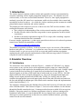
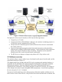
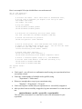
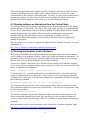
The CMU Wireless Network Emulator
User Manual
Version 1.2
May 12, 2008
Emulator Team
Carnegie Mellon University
[email protected]
1
Table of Contents
1. Introduction
1
2. Emulator Overview
1
3. Using the Emulator
4
4. Running experiments
5
5. Execution Control
6
6. Getting Help
8
2
1. Introduction
The wireless network emulator enables realistic and repeatable wireless experimentation by
accurately emulating wireless signal propagation in physical space. The emulator uses real
wireless nodes, so it is more accurate than simulation. However, since signal propagation is
emulated, it provides full control over experiments, unlike wireless testbeds where control and
repeatability are hard to achieve. As a result, the wireless emulator provides an attractive middle
ground between pure simulation and wireless testbeds.
This manual provides a high-level overview of how to use the CMU wireless emulator. After
reading this document, users should:
• Have a high level understanding of the wireless network emulator and its capabilities.
• Be able to decide which of the three usage modes is more appropriate for their (initial)
experiments.
• Be able to run simple experiments using the GUI or scripts, after consulting a separate
document that describes their commands.
For more complex experiments, e.g. that require special device drivers or Java-based experiment
control, more detailed documentation is available:
http://www.cs.cmu.edu/~emulator/doc/
This manual is organized as follows. In the next section we give an overview of the emulator
hardware and software. In Section 3, we explain how users can get access to the emulator and in
Sections 4 and 5 we give an overview of how to set up and control emulator experiments,
emphasizing the relative benefits and drawbacks of three different usage modes: GUI-based,
script-driven, and Java-based control.
2. Emulator Overview
2.1 Architecture
The architecture of the emulator is shown in Figure 1. A number of “RF nodes'' (e.g. laptops,
access points, or any wireless device in the supported frequency range) are connected to the
emulator through a cable attached to the antenna port of their wireless line cards. Each RF signal
is mixed with the local oscillator (LO) signal down to baseband and is then digitized. The
digitized signals are fed into a DSP engine that is built around one or more FPGAs. The DSP
engine models the effects of signal propagation (e.g. large-scale attenuation and small-scale
fading) on each signal path between each RF node. Finally, for each RF node, the DSP
combines the appropriately processed input signals from all the other RF nodes and sends it to
the line card through the antenna port. More details on the emulator design and implementation
can be found elsewhere [1, 2].
The emulator is managed using the Emulab software from the University of Utah in the context
of the CMUlab testbed. This is shown in Figure 1. Users access the emulator over the Internet
through the Emulab control node (ops). It manages testbed resources which all sit on a private
Ethernet. Fine grain control over emulator experiments is done by software running on the
Emulation Control Node. It controls both the RF devices (laptops in the current testbed),
allowing it to control applications on those devices, and the emulator hardware, providing
control over the wireless channels.
3
Figure 1: Wireless testbed based on signal propagation emulator
The deployed wireless network emulator at CMU has the following features:
• It supports up to 15 nodes.
• It supports the full 2.4 GHz ISM band. Otherwise, the emulator is technology neutral, i.e.
it is not tied a specific standard such as 802.11b/g.
• It keeps track of an emulated physical world in which wireless can move around under
the control of the user.
• It runs real-time signal propagation models that model attenuation, multi-path effects,
different types of fading, and directional antennas. Various parameters can be adjusted at
runtime, for example to model to effects of mobility. Parameters can be controlled
directly by the user or can be derived from the world model.
• The RF devices are laptops are laptops using Atheros 802.11b/g wireless cards.
2.2 Software overview
The emulator software consists of three layers: the channel model, physical world model, and the
experiment control layer (Figure 2).
The channel model layer, together with the FPGA code executing on the emulator hardware, is
responsible for the emulation of the signal propagation channels between the nodes (antennas)
attached to the emulator. Real-time emulation is done on the FGPA-based DSP, but it is
controlled by the control node. It can change parameters in the FPGA on the fly, for example to
reflect changes in location of nodes, through the DSP communicator. In an N node experiment,
the user can specify N x (N -1) channels.
The physical world model keeps track of the properties of the nodes and the world they move in.
In the current version of the software, it keeps track of the location and direction of antennas, and
4
for moving nodes, it also keeps track of speed and direction of movement. For more details on
the world model, see the “Physical World Model” page:
http://www.cs.cmu.edu/~emulator/doc/softwareDoc/World.html
In later versions of the system, the world model could also include information on the location of
obstacles, the building maps, etc.
Config
File
Initialize
Script
file
Timed
User
Application
Events
Threads
Control
GUI
Physical
World
Model
Channel
Channel
Channel
Channel
Channel
Channel
Channel
Channel
Channel
Channel
Model
Model
Model
Model
Model
Model
Model
Model
Model Model
DSP
Communicator
Figure 2: Software architecture
The experiment control layer is responsible for controlling the experiment by changing the state
of the physical world model and channel models. It has a number of components:
•
Experiment initialization: This module reads in the configuration file and initializes the
emulator hardware and software.
• Timed events: Similar to event-driven simulators, the primary mechanism for controlling
experiments is through a sequence of events that change the state of the physical world
and of the nodes. This module maintains an event queue that is ordered by time and
executes the events at the appropriate time. For simple experiments, the events are simply
read from a script file or are generated by the user through a GUI. For more complex
experiments, “power users” can write Java code to generate timed events directly.
• Application coordination: This module controls the applications on the emulator nodes.
Applications can be traffic generators (e.g. iperf) or real applications (e.g. web clients and
servers). The output of applications can either be written to a file or it can be sent back to
control node, where it can be analyzed in real-time by user-defined event handlers or user
threads. Power users can also write handlers that process the output locally on the
emulator nodes.
• The GUI, script file, and user threads modules support the three usage modes for the
emulator (Sections 5).
The different modules in the system interact using an event-listener paradigm. Modules (e.g. a
channel model) can register for events in another model (e.g. a change in user location or speed).
5
3. Using the Emulator
Users run experiments on the emulator by logging into the Emulation Control Node shown in
Figure 1. In this section we describe the process for getting an account and for logging in, both
locally and remotely. We also describe how to configure the emulator. We elaborate on how to
run experiments in the following four sections.
3.1 Request an Account
Accounts can be obtained by having the principle investigator for your project contact Peter
Steenkiste at [email protected]. Please provide some background on your project, the names of
the people who will need accounts, and proposed login names. If you had an emulator account
before we switched to using Emulab, please ignore Sections 3.2 and 3.3 and visit:
http:www.cs.cmu.edu/~emulator/doc/TransitionUser.html.
3.2 Apply for CMU Emulab Account
Once you have received approval from Peter Steenkiste, you should apply for an account through
CMUlab using the information provided in the approval message. Please execute the following
steps:
•
•
•
•
•
•
Go to http://boss.cmcl.cs.cmu.edu
Join the emulator project.
Complete the registration form ( you may upload ssh key later).
Check your email for an account message, and click on the verification link to confirm
that you requested the account.
Log in on http://boss.cmcl.cs.cmu.edu again using your account to complete the account
request process.
Check your email again - you will receive an email saying that your account is ready.
3.3 SSL Certificate
The next step is to create an SSL certificate on Emulab. The emulab and emulation control node
need to synchronize whenever you run an experiment on the wireless emulator and the Emulab
software uses an SSL certificate to authenticate users. You need to perform the following steps:
•
•
•
Go to "My Emulab"->"Profile"->"Generate SSL Cert"
Enter a pass phrase (your choice) and password to generate an SSL Cert; you will see a
message says "your new SSL certificate has been created. You can download your
certificate and ..."
Copy the ssl key from your home directory on ops.cmcl.cs.cmu.edu (~/ssl/) to your home
directory (~/ssl/) on emucontrol-1.ece.cmu.edu. This step will be automated at a later
time.
3.4 Remote Access
You are now ready to use the emulator. The Emulation Control Node is called (see Figure 1):
emucontrol-1.ece.cmu.edu
6
It runs Linux. You can log into this node anytime using a secure shell or secure telnet
connection.
In Section 2, we gave a high level overview of the emulator and its capabilities but the detailed
configuration of the deployed system (e.g. number of nodes, types of nodes, spectrum supported,
..) evolves over time. Up to date information on the deployed system can be found in the online
system configuration documentation:
http://www.cs.cmu.edu/~emulator/run/sys/SystemConfiguration.html
4. Running Experiments
We explained in Section 2 that there are three ways of running experiments on the emulator:
script driven, GUI based, and using Java. There are however some steps in the experiment
execution that are common to all three modes, as we explain in this section.
4.1 Channel Model
The emulator software has a built-in channel model that can be configured to represent a broad
range of useful signal propagation environments. In this built in model, each channel can consist
of multiple paths, each of which has a certain delay and attenuation. Each path can also have fast
Ricean fading based on a statistical model [3, 4]. Alternatively, the attenuation of a path can be
controlled through trace playback. The properties of a channel (i.e. delay, attenuation, Ricean
fading parameters) can either be fixed or derived from the physical world model. This built-in
model can implement a variety of signal propagation models, including simple coarse
attenuation, multi-path, and fast fading associated with mobile nodes. More details can be found
on the page “Signal Environment and Channel Models” on the documentation web page:
http://www.cs.cmu.edu/~emulator/doc/softwareDoc/SignalEnvironment.html
4.2 Create an Experiment on Emulab
As mentioned earlier, we use the Emulab software from the University of Utah to manage the
laptops in emulator. The Emulab software allocates the laptops to user experiments and also
offers a number of additional features, e.g. NFS for storing experimental results and the ability to
install your own kernels. Emulab users use NS scripts to define experiment so you will need to
create an NS script to allocate the resource you need in your experiment:
•
•
Login to CMUEmulab website ( http://boss.cmcl.cs.cmu.edu )
Go to "Experiment"->"Begin experiment", fill in the form:
Select-project: emulator
Your NS file: upload a NS file
Linktest Option: skip Linktest
check "Do Not Swap in" if you do not want to swap in your experiment immediately
• Submit
The NS file defines the resources required in an experiment, such as number of laptops needed,
desired properties of the laptops (e.g. support for multipath, software radios, etc.), the laptop
names, which OS image should be loaded for each laptop, etc.. Please refer to the Emulab
documentation for how to create an NS file:
http://boss.cmcl.cs.cmu.edu/tutorial/docwrapper.php3?docname=tutorial.html
7
Here is an example NS script which defines a two-node network:
set ns [new Simulator]
source tb_compat.tcl
# Allocate the nodes. Their "wifi-ness" is determined later,
# by the type of networks you request to be set up on them.
set nodew1 [$ns node]
set nodew2 [$ns node]
# only use pcd610
tb-set-hardware $nodew1 pcd610
tb-set-hardware $nodew2 pcd610
# A wireless lan connecting the first three nodes.
set lan0 [$ns make-lan "$nodew1 $nodew2" 11Mb 0ms]
# Choose the wireless lan protocol.
tb-set-lan-protocol $lan0 "80211b"
# Set an access point. This node becomes the access point;
# others in the LAN become stations of it. You can also set other
# modes for your LAN, such as Adhoc mode.
tb-set-lan-setting $lan0 "mode" "adhoc"
# Choose some other settings.
tb-set-lan-setting $lan0 "channel" 2
tb-set-node-lan-setting $lan0 $nodew1 "txpower" "auto"
# Select a wireless-capable image (i.e., FC6-WIRELESS)
# Let the other node default to RHL-STD (currently 9.0).
tb-set-node-os $nodew1 FC6w-EMU
tb-set-node-os $nodew2 FC6w-EMU
$ns rtproto Static
$ns run
•
•
•
•
•
Check email – you will receive a confirmation email saying your experiment has been
successfully created.
Check the current number of available nodes (pcd610) using
"Experiment"->"Node status".
If there are enough nodes, swap in your experiment using
"Emulator"->"Experiment"->"Swap in"
Check email again to confirm that your experiment was successfully swapped in
After you have been successfully swapped in, log into emucontrol-1.ece.cmu.edu, and
run:
emulatorDaemon <userID> <projectID> <experimentID>
This will allow emucontrol-1.ece.cmu.edu to retrieve the information for your
experiment.
8
While running applications on the laptops manually is sometimes convenient, it does not allow
repeatable experiments since the changes in the wireless channels (see Section 4.4) are not
synchronized with the execution of the applications. Of course, it is also inconvenient to have to
log into many laptops. For this reason, we allow users to configure the laptops and to start
applications from the Emulation Control Node, as is described in the next section.
4.3 Running software on the laptops from the Control Node
The emulator control software allows experimenters to run arbitrary applications on the laptops
from the Emulator Control Node. This can be done using scripts, the GUI, or programmatically
in Java. This is implemented using java’s Remote Method Invocation (RMI) interface. Besides
running the applications, the emulator API also provides a mechanism for capturing and
optionally filtering stdout and stderr from those applications. It enables a two-way
communication between the emulator control process on the control node and applications
running on the laptops.
We also provide a set of scripts to configure the laptops from the Emulator Controller. For more
information, see
http://www.cs.cmu.edu/~emulator/doc/operation/Operation.html
4.4 Running the Emulator Control Software
We briefly the emulation control software that you need to run to control the wireless channels.
It uses a number of environment variables. When your account was created on emucontrol-1, we
generated a .bashrc file that sets these variables automatically when you log in. If you change
this file, make sure you do not change the values of these variables.
A practice or “dummy” experiment can be run that will not actually use the emulator hardware.
To run such a practice experiment change to the experiment's run directory and type (NOTE: this
feature is temporarily not supported):
demoRun <hardWareConfigFile> <experimentConfigFile>
To run an actual “live” experiment that does use the emulator hardware, you will need to first
swap your experiment in, as described above. Once you have access to the laptops assigned by
CMUlab and are ready to run your experiment, change to the experiment's run directory and type
these following command:
startDaemons <pcHostname> (for all pcs in your experiment)
This command will start daemons on the emulator laptops nodes. This is needed for functions
such as automatic application creation and centralized I/O. You can now run experiments using
the following command:
emuRun <experimentConfigFile>
The emuRun command will parse the configuration files, contact the emulator hardware, and
bind to remote node daemons if necessary. Any specified user code will then be loaded, and
execution of the control script will begin. If the GUI is enabled, it will be displayed and updated
at runtime.
More information on how to run experiments can be found on the “Emulator Operation” page:
http://www.cs.cmu.edu/~emulator/doc/operation/Operation.html
9
5. Execution Control
The execution control system is responsible for controlling the execution of an experiment [4]. It
provides three interfaces: scripts that provide an easy-to-use method for conducting simple
experiments, programs that provide more advanced users with powerful control, and a graphical
user interface that enables interactive experimentation as well as visualization.
Examples of all three forms of execution control are available on the “Example Experiments”
web page:
http://www.cs.cmu.edu/~emulator/run/examples/examples.html
5.1 GUI
When conducting experiments with real hardware in a physical environment, there is frequently
an exploration phase during which wireless nodes are moved and applications are run in an
interactive fashion. For instance, a transmit rate selection experiment between a laptop and an
access point would likely include a phase where the laptop was moved around and performance
observed in an interactive fashion. The emulator makes it possible to perform this exploratory
phase without the need to actually move around the real world. We provide an interactive GUI
that can be used to move RF nodes around in an emulated physical environment and in the
corresponding emulated signal propagation environment. This GUI can be enabled even when
programmatic or scripted control is in use, for example to visualize an experiment. See the
documentation for programmatic and scripted control for more information.
More documentation on how to use the GUI is available on the “Emulator GUI” web page:
http://www.cs.cmu.edu/~emulator/doc/GUI/GUI.html
5.2 Scripts
The script interface is an easy-to-use interface for conducting basic experiments. This interface
allows users to define node movement and application execution without the need to write real
code. The scripting interface that we provide is deliberately simple. No looping, branching, or
variables are supported. Rather scripts are defined as lists of events using an XML-based syntax.
This restricted interface provides a very shallow learning curve, and makes writing basic
emulator experiments an easy task. This design maintains the key benefit of scripting - the
ability to run simple experiments - while supporting full programmatic control in a clean manner.
Scripts can add nodes to the emulator, stop emulation, control the movement of nodes in the
physical world, and execute commands on emulator nodes. Node movement may either be
specified on a point-by-point basis, or as a route.
More documentation on how to use the GUI is available on the “Emulator GUI” web page:
http://www.cs.cmu.edu/~emulator/doc/scripts/Scripts.html
5.3 Power users: Programmatic Control
Experiments that have requirements exceeding the capabilities of the script interface utilize the
programmatic interface. The control code running on the Emulation Controller is written in Java.
Users may write Java classes that are executed by the emulator controller, giving them full
10
access to the emulator functionality. Using the programmatic interface, experiments with
arbitrarily complex behavior can be created in a straightforward fashion.
More information on the structure of the emulator controller code and on the APIs available to
users is available on the “Java Code” page:
http://www.cs.cmu.edu/~emulator/doc/softwareDoc/UserCode.html
Javadocs for the emulator APIs are available at:
http://www.cs.cmu.edu/~emulator/doc/api/index.html
6. Getting Help
If you need help, send a message to [email protected] describing your problem with as
much detail as you can. Please include information on how your experiment was set up, which
nodes you were using, and what problem you saw. The more information you can provide to us,
the better, since this will help us to re-produce your problem.
References
[1] Glenn Judd and Peter Steenkiste, “Using Emulation to Understand and Improve Wireless
Networks and Applications”, 2nd Symposium on Networked Systems Design and
Implementation, Usenix and ACM, Boston, May 2-4, 2005.
[2] Glenn Judd and Peter Steenkiste, “Repeatable and Realistic Wireless Experimentation
through Physical Emulation”, Second Workshop on Hot Topics in Networking (HotNets II),
ACM, November 2003.
[3] R. Punnoose, P. Nikitin, and D. Stancil, “Efficient Simulation of Rician Fading within a
Packet Simulator”, In IEEE Conference on Vehicular Technology, Boston, September 2000.
[4] “A Software Architecture for Physical Layer Wireless Network Emulation”, Glenn Judd and
Peter Steenkiste, he First ACM International Workshop on Wireless Network Testbeds,
Experimental evaluation and CHaracterization (WiNTECH 2006), held in conjunction with
ACM MobiCom 2006, September 2006, Los Angeles.
11