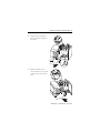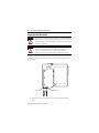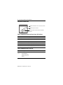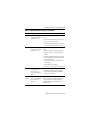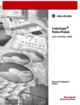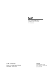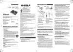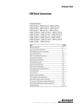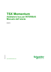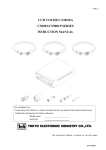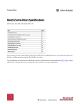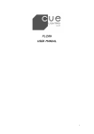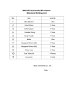
1
Installation Instructions
ControlLogix SERCOS interface Module
Catalog Number 1756-M03SE, 1756-M08SE, 1756-M16SE,
1756-M08SEG
The ControlLogix® SERCOS interface™ module links a ControlLogix
controller to SERCOS interface drives. The module uses fiber optic
connections for all field-side wiring.
To control up to this many
drives
Use this module
Which lets you control the
drives in these modes
Position
Velocity
3 SERCOS interface drives
1756-M03SE
yes
yes
yes
8 SERCOS interface drives
1756-M08SE
yes
yes
yes
16 SERCOS interface drives
1756-M16SE
yes
yes
yes
8 SERCOS interface drives that
are Extended Pack Profile
compliant
1756-M08SEG
yes
no
no
Torque
Before You Install the Module
Before you install your module:
✓
Install and ground a ControlLogix chassis.
✓
Install a ControlLogix power supply.
✓
Get the fiber optic cables for your application.
Publication 1756-IN572G-EN-P - May 2005
2 ControlLogix SERCOS interface Module
Important User Information
Solid state equipment has operational characteristics differing from those of
electromechanical equipment. Safety Guidelines for the Application, Installation and
Maintenance of Solid State Controls (Publication SGI-1.1 available from your local Rockwell
Automation sales office or online at http://www.ab.com/manuals/gi) describes some
important differences between solid state equipment and hard-wired electromechanical
devices. Because of this difference, and also because of the wide variety of uses for solid
state equipment, all persons responsible for applying this equipment must satisfy
themselves that each intended application of this equipment is acceptable.
In no event will Rockwell Automation, Inc. be responsible or liable for indirect or
consequential damages resulting from the use or application of this equipment.
The examples and diagrams in this manual are included solely for illustrative purposes.
Because of the many variables and requirements associated with any particular installation,
Rockwell Automation, Inc. cannot assume responsibility or liability for actual use based on
the examples and diagrams.
No patent liability is assumed by Rockwell Automation, Inc. with respect to use of
information, circuits, equipment, or software described in this manual.
Reproduction of the contents of this manual, in whole or in part, without written permission
of Rockwell Automation, Inc. is prohibited.
Throughout this manual, when necessary we use notes to make you aware of safety
considerations.
WARNING
IMPORTANT
ATTENTION
Identifies information about practices or circumstances that can cause an explosion in a
hazardous environment, which may lead to personal injury or death, property damage, or
economic loss.
Identifies information that is critical for successful application and understanding of the
product.
Identifies information about practices or circumstances that can lead to personal injury or
death, property damage, or economic loss. Attentions help you:
• identify a hazard
• avoid a hazard
• recognize the consequence
SHOCK HAZARD
Labels may be located on or inside the equipment (e.g., drive or motor) to alert people
that dangerous voltage may be present.
BURN HAZARD
Labels may be located on or inside the equipment (e.g., drive or motor) to alert people
that surfaces may be dangerous temperatures.
Publication 1756-IN572G-EN-P - May 2005
ControlLogix SERCOS interface Module 3
Documentation
To
See
Publication
number
set up and program motion control
Logix5000 Motion Module
User Manual
1756-UM006
program motion instructions
Logix5000 Controller Motion
Instructions Reference
Manual
1756-RM007
install, wire, and set up a
1394C-SJTxx-D drive
1394 SERCOS Interface
Multi Axis Motion Control
System
1394C-5.20
start up and troubleshoot a 1394 drive
with SERCOS
1394 SERCOS Integration
Manual
1394-IN024
install an Ultra3000 drive
Ultra3000 Hardware
Installation Manual
2098-IN003
start up and troubleshoot an
Ultra3000 drive with SERCOS
Ultra3000 SERCOS
Integration Manual
2098-IN005
design, install, and wire a
Kinetix 6000 drive
Kinetix 6000 Installation
Manual
2094-IN001
start up and troubleshoot a
Kinetix 6000 drive with SERCOS
Kinetix 6000 Integration
Manual
2094-IN002
use the 8720MC High Performance
Drive
8720MC High Performance
Drive User Manual
8720MC-UM001
SERCOS interface is a trademark of the Interests Group SERCOS interface ve.V. of Stuttgart, Germany.
Rockwell Automation is a member of the SERCOS NA.
Publication 1756-IN572G-EN-P - May 2005
4 ControlLogix SERCOS interface Module
How to Handle ControlLogix Components
ATTENTION
Preventing Electrostatic Discharge
This equipment is sensitive to electrostatic discharge, which can
cause internal damage and affect normal operation. Follow these
guidelines when you handle this equipment:
•
•
•
•
•
•
Touch a grounded object to discharge potential static.
Wear an approved grounding wriststrap.
Do not touch connectors or pins on component boards.
Do not touch circuit components inside the equipment.
If available, use a static-safe workstation.
When not in use, store the equipment in appropriate
static-safe packaging.
Install the Module
WARNING
When you insert or remove the module while backplane power
is on, an electrical arc can occur. This could cause an explosion
in hazardous location installations.
Be sure that power is removed or the area is nonhazardous
before proceeding. Repeated electrical arcing causes excessive
wear to contacts on both the module and its mating connector.
Worn contacts may create electrical resistance that can affect
module operation.
You can install or remove this module while chassis power and field-side
power are on.
Publication 1756-IN572G-EN-P - May 2005
ControlLogix SERCOS interface Module 5
1. Align the circuit board with
the top and bottom guides of
the chassis.
POWER
SERCOS interface
OK
2. Slide the module into the
chassis. Make sure the top and
bottom locking tabs snap into
place.
SERCOS interface
POWER
OK
Publication 1756-IN572G-EN-P - May 2005
6 ControlLogix SERCOS interface Module
Connect the Fiber Optic Cables
ATTENTION
ATTENTION
You must give a unique address to each drive on the SERCOS
ring. If you give 2 drives the same address on the same ring, both
drives respond to commanded motion. This could injure people
or damage equipment.
Under certain conditions, viewing the optical port may expose
the eye to hazard. When viewed under some conditions, the
optical port may expose the eye beyond the maximum
permissible exposure recommended in ANSI Z136.2, 1993.
ControlLogix SERCOS interface modules use fiber optics that are rated Class
1 for IEC LED safety classification. Under most viewing conditions, there is
no eye hazard.
receiver
transmitter
1. Remove the protective end caps from the receiver and transmitter
ports.
Publication 1756-IN572G-EN-P - May 2005
ControlLogix SERCOS interface Module 7
2. Insert each fiber optic cable into the appropriate port and screw on
finger tight. The cable that emits light is the transmitter.
Any break in the ring disables the SERCOS network and creates a warning a
on the SERCOS Ring Status LED.
Publication 1756-IN572G-EN-P - May 2005
8 ControlLogix SERCOS interface Module
Interpret the LED Indicators
SERCOS Communication Phase Status (CP) Indicator
SERCOS Ring Status Indicator
CP
Module Health and Communication Status (OK)
Indicator
OK
Table 1 SERCOS Communication Phase Status (CP) Indicator
State
Description
Solid Orange
Phase -1: Autobaud detection in progress.
OFF
Phase 0: looking for a closed ring.
Flashing Red
Phase 1: looking for active nodes.
Alternating Red/Green
Phase 2: configuring nodes for communication.
Flashing Green
Phase 3: configuring device specific parameters
Solid Green
Phase 4: configured and active.
Table 2 SERCOS Ring Status Indicator
State
Description
Recommended Action
Solid
Green
The ring, drive, and axes
are configured and
actively communicating
through to the nodes on
the ring.
None.
Publication 1756-IN572G-EN-P - May 2005
ControlLogix SERCOS interface Module 9
Table 2 SERCOS Ring Status Indicator (Continued)
State
Description
Recommended Action
Flashing
Red
The module has detected
a setup or configuration
fault with the ring.
Check your system setup and configuration as
follows:.
• Ensure drive and axes addresses are correct.
• Remove excess axes from ring.
• Make sure application program has selected
the proper Ring Cycle Period and Baud Rate.
Solid Red
The module has detected
a hardware or installation
fault with the ring.
Check your system hardware and installation as
follows:
• Make sure all cables are properly installed.
• Make sure cable is of the correct type and
length.
• Make sure application program has configured
the module’s ring transmit level to High when
using specified cables.
• Make sure the drive’s transmit levels are set
appropriately.
• Inspect cables for degradation.
• Inspect drives for any faults and correct them.
Off
Flashing
Green
The module has detected
no ring data on its
receiver or has not
successfully completed
phase 2.
Check your system and installation as follows:
The ring, drive, or axes
are not configured but at
least one has been
identified.
Not a problem if the system has not been
configured. If you are having trouble configuring
the ring, drive, and axes, make sure that the
RSLogix 5000 project is setup properly for the
equipment in use.
• Make sure all cables are properly installed
• Inspect cable for degradation and breakage.
• Inspect drives for faults.
Publication 1756-IN572G-EN-P - May 2005
10 ControlLogix SERCOS interface Module
Table 3 Module Health and Communication Status (OK) Indicator
State
Description
Recommended Action
Off
The module is not operating.
• Apply chassis power.
• Verify the module is completely
inserted into the chassis and
backplane.
Flashing Green
The module has passed internal
diagnostics, but has not
established active
communications.
None, if you have not configured
the module.
Solid Green
• Data is being exchanged.
None. The module is ready for
action.
• The module is in the normal
operating state.
Flashing Red
Solid Red
• A major recoverable failure has
occurred.
If an NVS update is in progress,
complete the NVS update.
• An NVS update is in progress.
If an NVS update is not in
progress: Reboot
A potential nonrecoverable fault
has occurred.
• Reboot the module.
Publication 1756-IN572G-EN-P - May 2005
• If the solid red persists, replace
the module.
ControlLogix SERCOS interface Module 11
Remove the Module from the Chassis, If Required
WARNING
When you insert or remove the module while backplane power
is on, an electrical arc can occur. This could cause an explosion
in hazardous location installations.
Be sure that power is removed or the area is nonhazardous
before proceeding. Repeated electrical arcing causes excessive
wear to contacts on both the module and its mating connector.
Worn contacts may create electrical resistance that can affect
module operation.
1. Push in and hold the top
and bottom locking tabs
on the module.
2. Pull the module out of
the chassis.
POWER
SERCOS interface
OK
Publication 1756-IN572G-EN-P - May 2005
12 ControlLogix SERCOS interface Module
Fiber Optic Cables
ATTENTION
Under certain conditions, viewing the optical port may expose
the eye to hazard. When viewed under some conditions, the
optical port may expose the eye beyond the maximum
permissible exposure recommended in ANSI Z136.2, 1993.
Table 4 Choose a Plastic Fiber Optic Cable
For use in:
Use this type of
plastic cable:
Length in meters
(inches)
Allen-Bradley
Catalog Number
electrical cabinet
non-jacketed
(Chlorinated
Polyethylene)
1 m (39 in)
2090-SCEP1-0
3 m (118 in)
2090-SCEP3-0
5 m (197 in)
2090-SCEP5-0
8 m (315 in)
2090-SCEP8-0
10 m (394 in)
2090-SCEP10-0
15 m (591 in)
2090-SCEP15-0
20 m (787 in)
2090-SCEP20-0
25 m (984 in)
2090-SCEP25-0
32 m (1260 in)
2090-SCEP32-0
1 m (39 in)
2090-SCVP1-0
3 m (118 in
2090-SCVP3-0
5 m (197 in)
2090-SCVP5-0
8 m (315 in)
2090-SCVP8-0
10 m (394 in)
2090-SCVP10-0
15 m (591 in)
2090-SCVP15-0
20 m (787in)
2090-SCVP20-0
25 m (984 in)
2090-SCVP25-0
32 m (1260 in)
2090-SCVP32-0
normal
environments
outside of an
electrical cabinet
standard jacket
(Polyvinyl Chloride)
Publication 1756-IN572G-EN-P - May 2005
ControlLogix SERCOS interface Module 13
Table 4 Choose a Plastic Fiber Optic Cable (Continued)
For use in:
Use this type of
plastic cable:
Length in meters
(inches)
Allen-Bradley
Catalog Number
harsh environment
nylon jacketed
1 m, (39 in)
2090-SCNP1-0
3 m, (118 in)
2090-SCNP3-0
5 m (197 in)
2090-SCNP5-0
8 m (315 in)
2090-SCNP8-0
10 m (394 in)
2090-SCNP10-0
15 m (591 in)
2090-SCNP15-0
20 m (787 in)
2090-SCNP20-0
25 m (984 in)
2090-SCNP25-0
32 m (1260 in)
2090-SCNP32-0
Table 5 Choose a Glass Fiber Optic Cable (Polyvinyl Chloride
Jacket for Use in Normal Environments)
Length in meters (inches)
Allen-Bradley Catalog Number
1 m (39 in)
2090-SCVG1-0
3 m (118 in)
2090-SCVG3-0
5 m (197 in)
2090-SCVG5-0
8 m (315 in)
2090-SCVG8-0
10 m (394 in)
2090-SCVG10-0
15 m (591 in)
2090-SCVG15-0
20 m (787 in)
2090-SCVG20-0
25 m (984 in)
2090-SCVG25-0
32 m (1260 in)
2090-SCVG32-0
50 m (1970 in)
2090-SCVG50-0
100 m (3937 in)
2090-SCVG100-0
Publication 1756-IN572G-EN-P - May 2005
14 ControlLogix SERCOS interface Module
Care and Handling of Fiber Optic Cables
ATTENTION
When you handle these components, take normal
precautions to prevent damage and/or degradation by
electrostatic discharge (ESD). The small junction size of
these components increases their susceptibility to damage
from ESD.
Good system performance depends on clean port optics and cable ferrules,
which keeps dust and small particles from blocking the optic path.
• When cables are not in use, keep the ends covered with the dust
covers that came with the cables.
• To clean the ends of the cables, use either:
– compressed air
– one of the following cleaners on a lint and strand free cotton swab:
Alcohols
Aliphatics
Other
methyl
hexane
soap solution
isopropyl
heptane
naphtha
isobutyl
For more information about the care, handling, and installation of fiber optic
cables see the Fiber Optic Cable Installation and Handling Instructions, publication
number 2090-IN010x-EN-P.
Publication 1756-IN572G-EN-P - May 2005
ControlLogix SERCOS interface Module 15
Specifications
Description
Value
Power Dissipation
5.0W
Backplane
Current
760 mA @ 5.1V dc
Operational
Temperature
IEC 60068-2-1 (Test Ad, Operating Cold),
IEC 60068-2-2 (Test Bd, Operating Dry Heat),
IEC 60068-2-14 (Test Nb, Operating Thermal Shock):
• 0 to 60°C (32 to 140°F)
Storage
Temperature
IEC 60068-2-1 (Test Ab, Un-packaged Non-operating Cold),
IEC 60068-2-2 (Test Bb, Un-packaged Non-operating Dry Heat),
IEC 60068-2-14 (Test Na, Un-packaged Non-operating Thermal Shock):
• -40 to 85°C (-40 to 185°F)
Relative Humidity
IEC 60068-2-30 (Test Db, Un-packaged Non-operating Damp Heat):
• 5 to 95% non-condensing
Vibration
IEC 60068-2-6 (Test Fc, Operating):
• 2g @ 10-500Hz
Operating Shock
IEC 60068-2-27 (Test Ea, Unpackaged Shock):
• 30g
Non-Operating
Shock
IEC 60068-2-27 (Test Ea, Unpackaged Shock):
• 50g
Emissions
CISPR 11:
Group 1, Class A
ESD Immunity
IEC 61000-4-2:
• 4kV contact discharges
• 8kV air discharges
Radiated RF
Immunity
IEC 61000-4-3:
• 10V/m with 1kHz sine-wave 80%AM from 80MHz to 2000MHz
• 10V/m with 200Hz 50% Pulse 100%AM at 900Mhz
• 10V/m with 200Hz 50% Pulse 100%AM at 1890Mhz
Enclosure Type
Rating
None (open-style)
2.5 mA @ 24V dc
Publication 1756-IN572G-EN-P - May 2005
16 ControlLogix SERCOS interface Module
Description
Value
Number of Drives
1756-M03SE
Up To 3 SERCOS interface drives
1756-M08SE
Up to 8 SERCOS interface drives
1756-M16SE
Up to 16 SERCOS interface drives
1756-M08SEG
Up to 8 SERCOS interface drives. You
must use drives that are Extended Pack
Profile compliant.
1756-M03SE
4 Mbits or 8 Mbits per second
1756-M08SE
4 Mbits or 8 Mbits per second
1756-M16SE
4 Mbits or 8 Mbits per second
1756-M08SEG
4 Mbits per second
SERCOS interface
Data Rate
SERCOS interface
Cycle Time
Important: Only Kinetix 6000 drives let you use a 0.5 ms cycle time.
Data rate
Number of drives
Cycle time
4 Mb
up to 2
0.5 ms
up to 4
1 ms
up to 8
2 ms
You can’t use more than 8 drives at a 4 Mb
data rate.
8 Mb
Plastic Fiber Optic
Cable
up to 4
0.5 ms
up to 8
1 ms
up to 16
2 ms
Transmission Range
1-32 meters
Core Diameter
980μm ± 60μm
Cladding Diameter
1000μm ± 60μm
Cable Attenuation
140 dB/km @ 650nm
Operating Temperature
-55 to 85° C
Connector
F-SMA standard screw-type connector
Bend Radius
2.5 cm
Publication 1756-IN572G-EN-P - May 2005
ControlLogix SERCOS interface Module 17
Description
Value
Glass Fiber Optic
Cable
Transmission Range
1-200 meters
Core Diameter
200μm ± 4μm
Cladding Diameter
230μm + 0 / − 10μm
Cable Attenuation
6.0 dB/km @ 820nm
Operating Temperature
-20 to 85° C
Connector
F-SMA standard screw-type connector
Bend Radius
2.5cm
Certifications
When marked, the module has the following certifications. See the Product
Certification link at www.ab.com for Declarations of Conformity, Certificates,
and other certification details.
Certification
Description
c-UL-us
UL Listed for Class I, Division 2 Group A,B,C,D Hazardous Locations,
certified for U.S. and Canada
CE
European Union 89/336/EEC EMC Directive, compliant with:
• EN 50082-2; Industrial Immunity
• EN 61326; Meas./Control/Lab., Industrial Requirements
• EN 61000-6-2; Industrial Immunity
• EN 61000-6-4; Industrial Emissions
C-Tick
Australian Radiocommunications Act, compliant with:
AS/NZS CISPR 11; Industrial Emissions
Publication 1756-IN572G-EN-P - May 2005
18 ControlLogix SERCOS interface Module
Environment and Enclosure Information
ATTENTION
Environment and Enclosure
This equipment is intended for use in a Pollution Degree 2 industrial
environment, in overvoltage Category II applications (as defined in IEC
publication 60664-1), at altitudes up to 2000 meters without derating.
This equipment is considered Group 1, Class A industrial equipment
according to IEC/CISPR Publication 11. Without appropriate precautions,
there may be potential difficulties ensuring electromagnetic compatibility
in other environments due to conducted as well as radiated disturbance.
This equipment is supplied as “open type” equipment. It must be mounted
within an enclosure that is suitably designed for those specific
environmental conditions that will be present and appropriately designed
to prevent personal injury resulting from accessibility to live parts. The
interior of the enclosure must be accessible only by the use of a tool.
Subsequent sections of this publication may contain additional information
regarding specific enclosure type ratings that are required to comply with
certain product safety certifications.
NOTE: See NEMA Standards publication 250 and IEC publication 60529, as
applicable, for explanations of the degrees of protection provided by
different types of enclosure. Also, see the appropriate sections in this
publication, as well as the Allen-Bradley publication 1770-4.1 (“Industrial
Automation Wiring and Grounding Guidelines”), for additional installation
requirements pertaining to this equipment.
Publication 1756-IN572G-EN-P - May 2005
ControlLogix SERCOS interface Module 19
North American Hazardous Location Approval
The following information applies when
operating this equipment in hazardous
locations:
Informations sur l'utilisation de cet équipement
en environnements dangereux:
Products marked "CL I, DIV 2, GP A, B, C, D" are
suitable for use in Class I Division 2 Groups A, B,
C, D, Hazardous Locations and nonhazardous
locations only. Each product is supplied with
markings on the rating nameplate indicating the
hazardous location temperature code. When
combining products within a system, the most
adverse temperature code (lowest "T" number)
may be used to help determine the overall
temperature code of the system. Combinations
of equipment in your system are subject to
investigation by the local Authority Having
Jurisdiction at the time of installation.
Les produits marqués "CL I, DIV 2, GP A, B, C, D" ne
conviennent qu'à une utilisation en environnements
de Classe I Division 2 Groupes A, B, C, D dangereux et
non dangereux. Chaque produit est livré avec des
marquages sur sa plaque d'identification qui
indiquent le code de température pour les
environnements dangereux. Lorsque plusieurs
produits sont combinés dans un système, le code de
température le plus défavorable (code de température
le plus faible) peut être utilisé pour déterminer le
code de température global du système. Les
combinaisons d'équipements dans le système sont
sujettes à inspection par les autorités locales
qualifiées au moment de l'installation.
WARNING
EXPLOSION HAZARD
• Do not disconnect
equipment unless power
has been removed or the
area is known to be
nonhazardous.
• Do not disconnect
connections to this
equipment unless power
has been removed or the
area is known to be
nonhazardous. Secure any
external connections that
mate to this equipment by
using screws, sliding
latches, threaded
connectors, or other
means provided with this
product.
• Substitution of
components may impair
suitability for Class I,
Division 2.
• If this product contains
batteries, they must only
be changed in an area
known to be
nonhazardous.
AVERTISSEMENT
RISQUE D'EXPLOSION
• Couper le courant ou
s'assurer que
l'environnement est classé
non dangereux avant de
débrancher l'équipement.
• Couper le courant ou
s'assurer que
l'environnement est classé
non dangereux avant de
débrancher les
connecteurs. Fixer tous les
connecteurs externes
reliés à cet équipement à
l'aide de vis, loquets
coulissants, connecteurs
filetés ou autres moyens
fournis avec ce produit.
• La substitution de
composants peut rendre
cet équipement inadapté à
une utilisation en
environnement de Classe I,
Division 2.
• S'assurer que
l'environnement est classé
non dangereux avant de
changer les piles.
Publication 1756-IN572G-EN-P - May 2005
Rockwell Automation Support
Rockwell Automation provides technical information on the web to assist you in using
its products. At http://support.rockwellautomation.com, you can find technical
manuals, a knowledge base of FAQs, technical and application notes, sample code and
links to software service packs, and a MySupport feature that you can customize to
make the best use of these tools.
For an additional level of technical phone support for installation, configuration and
troubleshooting, we offer TechConnect Support programs. For more information,
contact your local distributor or Rockwell Automation representative, or visit
http://support.rockwellautomation.com.
Installation Assistance
If you experience a problem with a hardware module within the first 24 hours of
installation, please review the information that's contained in this manual. You can also
contact a special Customer Support number for initial help in getting your module up
and running:
United States
1.440.646.3223 Monday – Friday, 8am – 5pm EST
Outside United States
Please contact your local Rockwell Automation representative for any
technical support issues.
New Product Satisfaction Return
Rockwell tests all of its products to ensure that they are fully operational when shipped
from the manufacturing facility. However, if your product is not functioning and needs
to be returned:
United States
Contact your distributor. You must provide a Customer Support case number
(see phone number above to obtain one) to your distributor in order to
complete the return process.
Outside United States
Please contact your local Rockwell Automation representative for return
procedure.
Back Cover
Publication 1756-IN572G-EN-P - May 2005
Supersedes Publication 1756-IN572F-EN-P - September 2004
PN 957955-39
Copyright © 2005 Rockwell Automation, Inc. All rights reserved. Printed in the U.S.A.