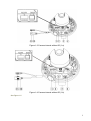
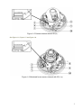
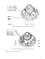
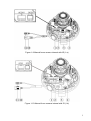
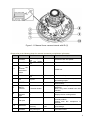
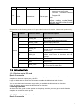
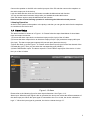
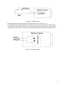
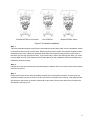
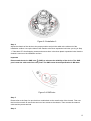
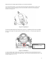
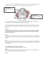
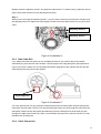
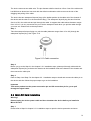
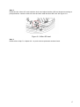
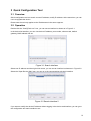
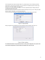
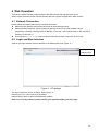
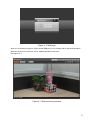
1
HD (IR) Vandal Proof Network Dome Camera Quick Start Guide Version 1.2.1 Welcome Thank you for purchasing our network camera! This quick start guide is designed to be a reference tool for your system. Please keep this start guide well for future reference. Please open the accessory bag to check the items one by one in accordance with the list below. Contact your local retailer ASAP if something is missing or damaged in the bag. Before your operation please read the following instructions carefully. 1.Electrical safety All installation and operation here should conform to your local electrical safety codes. The power shall conform to the requirement in the SELV (Safety Extra Low Voltage) and the Limited power source is rated 12V DC or 24V AC in the IEC60950-1. (Refer to general introduction) Please note: Do not connect two power supplying sources to the device at the same time; it may result in device damage! We assume no liability or responsibility for all the fires or electrical shock caused by improper handling or installation. We are not liable for any problems caused by unauthorized modification or attempted repair. 2.Transportation security Heavy stress, violent vibration or water splash are not allowed during transportation, storage and installation. 3.Installation Do not apply power to the camera before completing installation. Please install the proper power cut-off device during the installation connection. Always follow the instruction guide the manufacturer recommended. 4.Qualified engineers needed All the examination and repair work should be done by the qualified service engineers. We are not liable for any problems caused by unauthorized modifications or attempted repair. 5.Environment This series network camera should be installed in a cool, dry place away from direct sunlight, inflammable, explosive substances and etc. Please keep it away from the electromagnetic radiation object and environment. Please make sure the CCD (CMOS) component is out of the radiation of the laser beam device. Otherwise it may result in CCD (CMOS) optical component damage. Please keep the sound ventilation. Do not allow the water and other liquid falling into the camera. i Thunder-proof device is recommended to be adopted to better prevent thunder. The grounding studs of the product are recommended to be grounded to further enhance the reliability of the camera. 6. Daily Maintenance Please shut down the device and then unplug the power cable before you begin daily maintenance work. Do not touch the CCD (CMOS) optic component. You can use the blower to clean the dust on the lens surface. Always use the dry soft cloth to clean the device. If there is too much dust, please use the water to dilute the mild detergent first and then use it to clean the device. Finally use the dry cloth to clean the device. Please put the dustproof cap to protect the CCD (CMOS) component when you do not use the camera. Dome enclosure is the optical component, do not touch the enclosure when you are installing the device or clean the enclosure when you are doing maintenance work. Please use professional optical clean method to clean the enclosure. Improper enclosure clean method (such as use cloth) may result in poor IR effect of camera with IR function. 7. Accessories Be sure to use all the accessories recommended by manufacturer. Before installation, please open the package and check all the components are included. Contact your local retailer ASAP if something is broken in your package. Accessory Name Amount Network Camera Unit 1 Quick Start Guide 1 Installation Accessories Bag 1 CD 1 ii Table of Contents 1 Structure ................................................................................................................................. 1 1.1 Dimensions ............................................................................................................... 1 1.2 Port Description ........................................................................................................ 1 1.3 Bidirectional talk ....................................................................................................... 7 1.3.1 Device-end to PC-end....................................................................................... 7 1.3.2 PC-end to the Device-end ................................................................................ 7 1.4 2 Alarm Setup .............................................................................................................. 8 Installation ............................................................................................................................ 10 2.1 Device Installation Introduction ............................................................................. 10 2.2 Device Installation Steps ....................................................................................... 10 2.2.1 2.2.2 2.2.3 2.2.4 2.3 3 4 General Installation ......................................................................................... 10 Manual Zoom Lens Focus Operation ............................................................ 14 Side Cable Exit ................................................................................................ 15 Cable Connection ............................................................................................ 15 Micro SD Card Installation .................................................................................... 16 Quick Configuration Tool .................................................................................................... 18 3.1 Overview ................................................................................................................. 18 3.2 Operation ................................................................................................................ 18 Web Operation ..................................................................................................................... 20 4.1 Network Connection............................................................................................... 20 4.2 Login and Main Interface ....................................................................................... 20 Appendix Toxic or Hazardous Materials or Elements ............................................................. 22 iii 1 Structure 1.1 Dimensions You can refer to the following figures for dimension information. The Unit is mm. See Figure 1-1 and Figure 1-2. Figure 1-1 Dimension 1 Figure 1-2 Dimension 2 1.2 Port Description For the non-IR series product, the interface is shown as in Figure 1-3 and Figure 1-4. Note: Figure in this chapter are all for reference only, and please refer to model 1-a and 1-b according to actual product. 1 Figure 1-3 Camera internal without IR (1-a) Figure 1-4 Camera internal without IR (1-b) See Figure 1-5. 2 Figure 1-5 Camera internal without IR (2) See Figure 1-6, Figure 1-7 and Figure 1-8. Figure 1-6 Motorized focus camera internal with IR (1-a) 3 Figure 1-7 Motorized focus camera internal with IR (1-b) Figure 1-8 Motorized focus camera internal with IR (2) See Figure 1-9, Figure 1-10 and Figure 1-11. 4 Figure 1-9 Manual focus camera internal with IR (1-a) Figure 1-10 Manual focus camera internal with IR (1-b) 5 Figure 1-11 Manual focus camera internal with IR (2) Please refer to the following sheet for external connection port definition information. SN Port Port Name 1 POWER 2 POWER 3 Cable exit of the external connected cable / 4 LAN RJ45 port 5 I/O I/O port 6 RESET Reset button / 7 AUTO FOCUS 5-direction button / 8 Status indicator light AC 24V power port DC 12V power port network Connector Function Description / Connect to AC 24V power. / Connect to DC 12V power. / Cable exit. Ethernet port Network cable port. It includes alarm input/output, audio and analog output. Reset button. It is to restore factory default setup. Adjust lens angle of view and definition. Note: Only some models have this function. / / / 9 Fan port 10 Micro SD Micro SD slot entry 11 POWER 12V power port Display device running status. / / card Micro card / SD Connect to fan to reduce device internal problem. Please note this component is optional. Connect to Micro SD card to realize local storage. The power port of the external connected cable. 6 12 LAN Network port Ethernet port Default input is DC 12V. The network port of the external connected cable. Connect to standard Ethernet port. Support PoE. Note: Before making crystal head, pull the anti-dust cover through network cable. Please refer to the following sheet for I/O port cable function information. Note: actual product may vary. Port Cable SN Cable Port Name Function Description Name I/O Port 1 ALARM_NO Alarm output port. Output alarm signal to alarm device. NO: Normal open alarm output end. 2 ALARM_COM Alarm output public end. 3 GND Ground end. 4 ALARM_IN Alarm input port. It is to receive the on-off signal from the external alarm source. 5 GND Ground end. 6 AUDIO_IN 7 AUDIO_OUT 8 GND Ground end. 9 VIDEO_OUT Output analog video signal. It can connect to TV monitor to view video. Input audio signal. It is to receive the analog audio signal from the devices such as pickup. Output audio signal to devices such as sound box. 1.3 Bidirectional talk 1.3.1 Device-end to PC-end Device Connection Please connect the speaker or the MIC to the audio input port of the device. Then connect the earphone to the audio output port of the PC. Login the Web and then click the Talk button to enable the bidirectional talk function. You can see the button becomes orange after you enabled the bidirectional talk function. Click Talk button again to stop the bidirectional talk function. Listening Operation At the device end, speak via the speaker or the pickup, and then you can get the audio from the earphone or sound box at the pc-end. 1.3.2 PC-end to the Device-end Device Connection 7 Connect the speaker or the MIC to the audio input port of the PC and then connect the earphone to the audio output port of the device. Login the Web and then click the Talk button to enable the bidirectional talk function. You can see the button becomes orange after you enabled the audio talk function. Click Talk button again to stop the bidirectional talk function. Please note the on-site listening operation is null during the bidirectional talk process. Listening Operation At the PC-end, speak via the speaker or the pickup, and then you can get the audio from the earphone or sound box at the device-end. 1.4 Alarm Setup The alarm interface is shown as in Figure 1-12. Please follow the steps listed below for local alarm input and output connection. 1) Connect the alarm input device to the alarm input port (No.4 pin) of the I/O cable. 2) Connect the alarm output device to the alarm output port (No.1 pin) and alarm output public port (No.2 pin). The alarm output port supports NO (normal open) alarm device only. 3) Open the Web, go to the Figure 1-12. Please set the alarm input 01 port for the first channel of the I/O cable (No.4 pin). Then you can select the corresponding type (NO/NC.) 4) Set the WEB alarm output. The alarm output 01 is for the alarm output port of the device. It is the No.1 pin of the I/O cable. Figure 1-12 Alarm Please refer to the following figure for alarm input information. See Figure 1-13. Alarm input: When the input signal is idle or grounded, the device can collect the different statuses of the alarm input port. When the input signal is connected to the 5V or is idle, the device collects the logic “1”. When the input signal is grounded, the device collects the logic “0”. 8 Figure 1-13 Alarm input Please refer to the following figure for alarm output information. See Figure 1-14. Port ALARM_COM and Port ALARM_NO composes an on-off button to provide the alarm output. If the type is NO, this button is normal open. The button becomes on when there is an alarm output. If the type is NC, this button is normal off. The button becomes off when there is an alarm output. Figure 1-14 Alarm output 9 2 Installation Important Before you complete the installation and setup, do not remove the electrostatic attraction film on the transparent enclosure. Otherwise it may result in injury. After remove electrostatic attraction film, do not touch dome enclosure in case it may leave stain. Before the installation, please make sure the installation surface can sustain at least 3X weight of the bracket and the camera. 2.1 Device Installation Introduction Please refer to Figure 2-1 for device installation space information. You can use screws (diameter is less than 4.5mm) to secure the device. You can see there are installation position map and installation screws in the accessories bag for you to install the device conveniently. Figure 2-1 Installation 1 2.2 Device Installation Steps 2.2.1 General Installation The general interface is shown as in Figure 2-2. 10 IR Motorized Zoom Lens Series Non-IR Series IR Manual Zoom Series Figure 2-2 General installation Step 1 Take the installation position map from the accessories bag and then paste it on the installation ceiling or the wall according to the monitor area. Please dig three bottom holes of the plastic expansion bolts according to the map. Take three expansion bolts from the accessories bag and then insert them to the holes you just dug and then fix firmly. If you need to dig a hole to pull through the cable, you need to dig a cable exit hole (The diameter is more than 28mm) on the installation surface according to the installation positioning map. Step 2 Use the inner hex wrench from the accessories bag to unfasten the 3 hex screws on the dome camera enclosure to open it. Step 3 Please remove the device cable (Provided) network port and the power terminal. Use the inner hex wrench (Provided) to remove the 2 inner hex screws from the dome driver module. Then please follow the prompt on the device to push the metal hook to two sides. Remove the dome driver module from the chassis. See Figure 2-3. 11 Figure 2-3 Installation 2 Step 4 Adjust the chassis of the device to the proper position and pull the cable to the cable exit of the installation surface. Line up the holes of the chassis to the three expansion bolt holes you dug in Step 1. Take three ST3.0 self-tapping screws and secure them in the three plastic expansion bolts. Now the chassis is secure on the installation surface. Important Please earth the device GND hole (GND) to enhance the reliability of the device. The GND port is near the cable exit of the rear panel. The GND screw thread specification is M3-6mm. Figure 2-4 GND hole Step 5 Please refer to the Step 3 to put the driver module back to the metal hooks of the chassis. Then use the inner hex wrench to secure the two inner hex screws to the chassis. Then connect the network cable and the power terminal. Step 6 12 Adjust the lens to the proper angle according to your monitor requirements. a) For the IR series product, you can skip current step and go the step b) directly. For the non-IR series product, push the port slightly to remove the decoration enclosure from the black plastic enclosure. See Figure 2-5. Figure 2-5 Installation 3 b) Lens pan rotation angle setup. Please refer to Figure 2-6 to unfasten the lock screw A and adjust the pan monitor angle to the proper position. Then fix the lock screw A. The pan angle ranges from 0°~+350°. Lock Screw A Adjust lend pan rotation angle. Figure 2-6 Installation 4 c). Lens tilt rotation angle. Please refer to Figure 2-7 to unfasten the lock screw B and lock screw C and adjust the tilt monitor angle to the proper position. Then fix the lock screw B and lock screw C. The tilt angle ranges from -23°~+73°. 13 d). Image pan rotation angle setup. Please refer to Figure 2-7 to turn lock screw D to adjust the video pan angle. Then fix the lock screw B and C. The video pan angle ranges from 0°~+350°. Lock screw B/C Adjust lens tilt rotation angle. Lock screw D Adjust lend pan rotation angle. Figure 2-7 Installation 5 e) For the motorized zoom series product, please skip current step. Please refer to chapter 2.2.2 for the lens zoom and focus operation of the manual focus series product. f) For the IR series product, please skip current step and complete the angle setup directly. For the non-IR series product, please put back the black plastic decoration enclosure to complete the angle setup. Important Please note Figure 2-6 and Figure 2-7 is based on the IR motorized zoom camera. For the IR manual zoom camera and non-IR series product, the lock screw position and the lens angle adjustment are the same. Step 7 Line up the dome camera protection enclosure to the cable exit on the side panel. Put the enclosure back and then use the inner hex wrench to secure the 3 inner hex screws firmly. Now the installation is complete. Note Usually we recommend, after the installation, please take the three white static protection gaskets from the accessories bag and insert them to the screw holes of the protection enclosure. It is to enhance device reliability. 2.2.2 Manual Zoom Lens Focus Operation The manual zoom lens focus interface is shown as in Figure 2-8. Step 1 Slightly loosen the adjusting screw E and push the adjust screw E to make it swing. Adjust the lens focus to the proper position according to the displayed video. Step 2 14 Slightly loosen the adjusting screw F and push the adjust screw F to make it swing. Adjust the lens to get the clear video and then fix the adjusting screw firmly. Step 3 When you are securing the adjusting screw F, you can see the video may become blur. Please push the adjusting screw E to adjust the video slightly. Please secure the adjust screw E if you get a clear video. Adjusting Screw E Adjusting Screw F Figure 2-8 Installation 6 2.2.3 Side Cable Exit If you adopt side cable exit when you are installing the device, you need to remove the plastic decoration plug from the side of the chassis. Use the proper tool to dig through the part specified in Figure 2-9 to form a cable exit. Put the plastic decoration plug back to the chassis and then pull the cable through the side panel of the chassis. Dig through here Figure 2-9 Installation 7 For some special user, he may need the metal protection tube to protect when he pulls through the cable from the side cable. There is PG11screw thread port when you pull through the cable from the side panel. Please remove the plastic decoration plug from the side panel of the chassis and pull through the cable to the tunnel of the PG11 screw thread. Now secure the tunnel in the PG11 screw threaded hole of the device. 2.2.4 Cable Connection 15 The device reserves two cable exits. The pin diameter shall be less than 15mm. One of the cable exits has M22 screw thread and can work with the default combination cable to remove the risk of the dragging and pulling of the cable. The device has two waterproof airproof plugs (One default position is the cable exit of the chassis of the device and the other is in the accessories bag.). The waterproof airproof plug has two functions. One is to fill in the cable exit and pull through the cable. It supports the cable whose diameter ranges from 4.0~6.0. It is very convenient for you to do the waterproof work when you pull the cable through your own exit. Please refer to the steps listed. Step 1 Take the waterproof airproof plug out, pull the cable (diameter ranges from 4.0 to 6.0) through the waterproof airproof plug. See Figure 2-10. Figure 2-10 Cable connection Step 2 Before you go to the Step 4 in the chapter 2.2.1 installation steps, please pull through cable with the waterproof airproof plug to the device chassis via the installation hole at the bottom of the chassis and then connect the cable pins. Step 3 Refer to Step 4 and Step 5 in the chapter 2.2.1 installation steps to install and connect the cable pin to the device and then follow the proper steps to go on the installation. Important This series product has the power connection pin and I/O connection pin for you to pull through the signal cable. 2.3 Micro SD Card Installation Warning! Please unplug the device power cable and then shutdown the device before you install the Micro SD card. Step 1 Please refer to Step2 in chapter 2.2.1 installation steps to open the device protection enclosure. 16 Step 2 Please find the “Micro SD” mark inside the device and adjust the Micro SD card direction according to prompt direction. Insert the card to the slot and then install the Micro SD card. See Figure 2-11. Figure 2-11 Micro SD card Step 3 Please refer to Step 7 in chapter 2.2.1 to put the device protection enclosure back. 17 3 Quick Configuration Tool 3.1 Overview Quick configuration tool can search current IP address, modify IP address. At the same time, you can use it to upgrade the device. Please note the tool only applies to the IP addresses in the same segment. 3.2 Operation Double click the “ConfigTools.exe” icon, you can see an interface is shown as in Figure 3-1. In the device list interface, you can view device IP address, port number, subnet mask, default gateway, MAC address and etc. Figure 3-1 Search interface Select one IP address and then right click mouse, you can see an interface is shown as in Figure 3-2. Select the “Open Device Web” item; you can go to the corresponding web login interface. Figure 3-2 Search interface 2 If you want to modify the device IP address without logging in the device web interface, you can go to the configuration tool main interface to set. 18 In the configuration tool search interface (Figure 3-1), please select a device IP address and then double click it to open the login interface. Or you can select an IP address and then click the Login button to go to the login interface. See Figure 3-3. In Figure 3-3, you can view device IP address, user name, password and port. Please modify the corresponding information to login. Please note the port information here shall be identical with the port value you set in TCP port in Web Network interface. Otherwise, you cannot login the device. If you are using device background upgrade port 3800 to login, other setups are all invalid. Figure 3-3 Login prompt After you logged in, the configuration tool main interface is shown as below. See Figure 3-4. Figure 3-4 Main interface For detailed information and operation instruction of the quick configuration tool, please refer to the Quick Configuration Tool User’s Manual included in the resources CD. 19 4 Web Operation This series network camera products support the Web access and management via PC. Web includes several modules: Monitor channel preview, system configuration, alarm and etc. 4.1 Network Connection Please follow the steps listed below for network connection. Make sure the network camera has connected to the network properly. Please set the IP address, subnet mask and gateway of the PC and the network camera respectively. Network camera default IP address is 192.168.1.108. Subnet mask is 255.255.255.0. Gateway is 192.168.1.1 Use order ping ***.***.***.***(* network camera address) to check connection is OK or not. 4.2 Login and Main Interface Open IE and input network camera address in the address bar. See Figure 4- 1. Input your IP address here Figure 4- 1 IP address The login interface is shown as below. See Figure 4- 2. Please input your user name and password. Default factory name is admin and password is admin. Note: For security reasons, please modify your password after you first login. 20 Figure 4- 2 Web login After you successfully logged in, please install WEB plug-in unit. Please refer to the Web Operation Manual included in the resource CD for detailed operation instruction. See Figure 4- 3. Figure 4- 3 Web monitoring window 21 Appendix Toxic or Hazardous Materials or Elements Toxic or Hazardous Materials or Elements Component Name Pb Hg Cd Cr VI PBB PBDE Circuit Board Component ○ ○ ○ ○ ○ ○ Device Case ○ ○ ○ ○ ○ ○ Wire and Cable ○ ○ ○ ○ ○ ○ Packing Components Accessories ○ ○ ○ ○ ○ ○ ○ ○ ○ ○ ○ ○ O: Indicates that the concentration of the hazardous substance in all homogeneous materials in the parts is below the relevant threshold of the SJ/T11363-2006 standard. X: Indicates that the concentration of the hazardous substance of at least one of all homogeneous materials in the parts is above the relevant threshold of the SJ/T11363-2006 standard. During the environmental-friendly use period (EFUP) period, the toxic or hazardous substance or elements contained in products will not leak or mutate so that the use of these (substances or elements) will not result in any severe environmental pollution, any bodily injury or damage to any assets. The consumer is not authorized to process such kind of substances or elements, please return to the corresponding local authorities to process according to your local government statutes. Note: This quick start guide is for reference only. Slight difference may be found in user interface. All the designs and software here are subject to change without prior written notice. All trademarks and registered trademarks mentioned are the properties of their respective owners. If there is any uncertainty or controversy, please refer to the final explanation of us. Please visit our website or contact your local service engineer for more information. 22