1
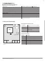
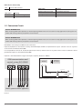
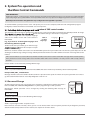
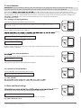
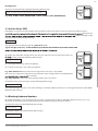
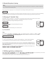
Quad-band GSM dialer
ELO-GSM51
Installation / User Manual v1.0
Safety instructions
Please read and follow these safety guidelines and assembly instructions in order to maintain safety of operators and people around:
•
•
•
•
•
•
•
Alarm and control device ELO-GSM51 (further referenced as the system) contains an integrated radio transceiver operating in GSM
850/900/1800/1900 MHz bands.
Don’t use the system where it can interfere with other devices and cause any potential danger.
Don’t mount the system next to medical equipment or devices, if they require so.
Don’t use the system in hazardous environment.
Don’t expose the system to high humidity, chemical environment or mechanical impacts.
Don’t attempt to personally repair the system.
System label is on the bottom side of the device.
ELO-GSM51 is a device mounted in limited access areas. Any system repairs must be done only by qualified, safety aware
personnel.
Mains power must be disconnected before any installation or tuning work starts. The system installation or maintenance
must not be done during stormy conditions.
The system must be powered by main 10-24V 50Hz ~200mA AC or 10-24V
200mA DC power supply
External power supply can be connected to AC mains only inside installation room with automatic 2-pole circuit breaker capable of disconnecting circuit in the event of short circuit or over-current condition. Open
circuit breaker must have a gap between connections of more than 3mm.
Phase
Null
PE
AC 230V
50 Hz/DC 24V
ELO-GSM51
USB cable
Fuse F1 type C1S 2.5A. Blown fuse cannot be replaced by the user and the replacement fuses have to be exactly the same as
indicated by the manufacturer.
device that the system Esim251 is powered from.
device of the external power supply or any other linked
If you use I security class computer for setting the parameters it must be connected to earth.
The WEEE (Waste Electrical and Electronic Equipment) marking on this product or its documentation indicates that in the EU the
product must not be disposed of together with household waste.
Limited Liability
The buyer must agree that the system will reduce
re, theft, burglary or other dangers but
does not guarantee against such events.
Elotec AS will not take any responsibility regarding personal, property or revenue loss while using
the system.
Elotec AS responsibility according to local laws
does not exceed value of the purchased system.
Elotec AS is not responsible for the quality of
cellular services
CONTENT
1. General Information
1.1 Function .......................................................................................................4
1.2 Operation Description.............................................................................4
cations .........................................................................5
1.4 Connector Functionality .........................................................................5
1.5 Connection Circuit. ...................................................................................6
1.6 System Installation ...................................................................................7
2. System Pre-operation and the Main Control Commands
2.1 Selecting device language
cation of SMS central number ...........................................8
2.2 Password Change .....................................................................................8
2.3 User Numbers .............................................................................................9
2.3.1 Saving or Changing Numbers ..............................................9
cation of Saved Numbers .............................................9
2.3.3 Deletion of Saved Numbers. .................................................9
2.4 Date and Time Settings ..........................................................................9
3. Additional System Capabilities
Package Content:
The system ELO-GSM51 ............ 1 pcs
Manual ............................................. 1 pcs
GSM antenna ................................ 1 pcs
Fastening holders ........................ 3 pcs
About User Manual
This document describes remote alarm system
ELO-GSM51, its operation and installation.
It is very important to read User Manual before
start using the system.
rst two chapters.
Chapter 3 and 4 describe additional system capabilities.
3.1
3.2
3.3
3.4
3.5
3.6
3.7
3.8
Renaming Zones and Controlled Output ...................................... 10
Enabling/Disabling Zones................................................................... 10
Info on Status SMS...................................... ........................................... 11
Blocking Unknown Numbers............................................................. 11
Remote Microphone Listening ......................................................... 12
Managing C1 and C2 Controlled Outputs. Timer ....................... 12
SMS Message Delivery to Multiple Users ..................................... 12
Calling all users ...................................................................................... 13
4. Appendix
4.1 Restoring Default Parameters. .......................................................... 14
4.2 ELO-GSM51 ConfigTool configuration software ................... 14
4.3 Technical Support .................................................................................. 14
1. General Information
1.1 Function
ELO-GSM51 is a microcontroller based device used to inform users about the alarm in automatic or security systems and control one
electric appliance -relay.
1.2 Operation Description
Description of factory default settings.
Alarm and control systemELO-GSM51 works over GSM network. It works 24/7, i. e. it always reacts to the incoming signal.
re alarm sensor, door sensor, any other sensor or PGM output gets activated, ELO-GSM51 sysve possible users answers the phone or rejects the
call or until the call will be ended by the mobile service provider. After hanging up the phone the system turns back to the previous
status. An SMS message with the name of the activated input (zone) is being sent until its successful delivery to one of the users or
until it is delivered to all users. If you answer the call, the microphone gets activated for listening. After “hanging up the phone” the
systems turs back to the previous status of active security.
ELO-GSM51 can control 1 electronic appliance (a relay) sending a password and a special command from a GSM phone of any of the
users. You can, for example, turn on the heating, lighting, lift the gates, blinds etc.
The system will ignore requests coming from unknown telephone number or SMS message with wrong password.
gurable system possibilities.
Input types
Ways of activating an event
Normally open NO
Operation only when the signal is transmitted.
Normally closed NC
Operation only when the signal is switched.
Event when the input is
activated (Alarm)
SMS is delivered when the signal is transmitted to the input.
Event when the input is restored SMS is delivered when the previously transmitted signal in the
(Restore)
input disappears.
Impulse counting
SMS
Ways of transmitting an event
Only SMS or various call combinations can be chosen. It is also
possible to use only calls. Any of the users can be assigned only
SMS or only calls or call combinations. Besides, any of the users can
be assigned a particular input (zone) or their combination.
gure the system so that when input Z1 is
activated SMS are sent only to users NR1 and NR5, and when Z2
is activated SMS is sent to all users and the call would be for NR4
and so on.
When the functions SMSALL and CALLSALL are set SMS messages
are sent to all users and the call would be delivered regardless of
the fact whether the call was answered, rejected etc.
Calls
by SMS
Ways of controlling output
(relay)
Event register
4
SMS is delivered if the number of te preset number of impulses in
the input is exceeded. Max value is 4294967295 impulses.
by a call
1. for a permanent status
2. for a set period
3. for a set hour
:
by sending the command by SMS
.
1. for a permanent status
2. for a set period
3. toggle (relay status changes after each call)
:
Automatic turning on at the
preset hour
The relay can be turned on for a set period at a set hour.
E. g. the relay is turned on at 18:00 and it is on for 5 hours. After 5
hours it turns on automatically notifying the user about that.
Event register function
When the computer is connected it is possible to see activations,
network strength etc.
EN
cations
cations
Supply voltage
Current used in standby mode
GSM modem frequency
Number of “low” level (negative) inputs
Number of “high” level (positive) inputs
Allowable “low” level (negative) input voltage values
Allowable “high” level (positive) input voltage values
Number of outputs
Output type
C1 output maximum commutating values
Dimensions
Operating temperature range
10-24V 50Hz ~ 200mA max / 10-24V
50mA max
850/900/1800/1900 MHz
4
1
0-1.6V
5-50V
1
NO (relay)
1A/24V DC; 0,5A/125V AC
82x63x20mm
-20…+55oC
(-30...+55oC with limitations)
200mA max
1.4 Connector Functionality
Short explanation of the main units
USB
SIM
CARD
ANT
GSM
MODEM
LED1
LED2
MIC
AC/DC
RELAY
-
DEFAULT D1 D2
- COM Z5 Z4 Z3 Z2 Z1
Picture 1
INSTALLATION MANUAL ELO-GSM51 V1.0
GSM MODEM
SIM CARD
LED
DEFAULT
ANT
USB
GSM network 850/900/1800/1900 MHz
modem
SIM card
Light-emitting diodes indicator
Connectors (D1 and D2) for restoring
default settings
GSM antenna SMA type connector
Mini USB connector
Connector functionality
Labeling
AC/DC
RELAY
RELAY
COM
Z5
Z4
Z3
Z2
Z1
Explanation
Power supply pins
Dry relay contact. Normally open (NO)
Dry relay contact. Normally open (NO)
Common pin
“Low” level input Z5
“Low” level input Z4”
“Low” level input Z3
“High” level input Z2
“Low” level input Z1
5
LED indicators functionality
LED1
LED2
Indicates SIM card status
Indicates network status
LED1 status
OFF
Meaning
SIM card is working properly
ON
SIM card error
LED2 status
OFF
Meaning
No network connection
Blinking 3 times per second
Poor network connection
Blinking 1 time per second
Medium network connection
ON
Excellent network connection
1.5 Connection Circuit
USEFUL INFORMATION
When choosing GSM cellular provider, it is worth inquiring whether the service is used in security application assuring fast and
reliable SMS message delivery and phone call connection.
USEFUL INFORMATION
When choosing GSM cellular provider, it is worth inquiring whether the service is used in security application assuring fast and
reliable SMS message delivery and phone call connection.
ELO-GSM51 and security unit COM must be connected.
Inputs Z1,Z3,Z4,Z5 are connected to security unit PGM outputs if PGM are implemented as open collector circuit or any other
circuit and if it commutates with COM.
It is also possible to connect Z1, Z3, Z4, Z5 inputs to, for instance, motion sensor or any other sensor as well as automatics device
provided the inputs are commutated with COM.
Input Z2 is commutated with a “high level” impulse. Impulse duration is >600ms.
GSM communication and
control system ELO-GSM51
AC/DC
RELAY
COM Z5 Z4
Z3
Z2
AC/DC
Metal box
PE contact
Z1
Fuse 500 mA
~10-24V
Picture3 AC power supply connection circuit
PGM2
PGM1
PGM3
PGM4
PGM5
+12V
HIGH
LEVEL
Alarm system or other appliance
Picture 2
6
~230V 50Hz
EN
1.6 System Installation
ammable plastic enclosure. If the metal enclosure and transformer is used it
is necessary to ground the enclosure using yellow/green colour cable. For the connection of 230V transformer use 3x0.75 mm2
1 thread double isolated cable. The primary circuit of the transformer must be connected through 0.5A fuse. 230V power supply
cables cannot be grouped with low voltage cable group. For the connection of power supply and output connectors use 1 thread
2x0.75 mm2 cable. For the connection of input/output connectors use 0.50 mm2 1 thread cable.
1. Fasten the system in the box using fastening holders.
2. Place SIM card in the holder but make sure that SIM card PIN code is disabled. (PIN code can be disabled by putting SIM card
into mobile phone and following proper menus). SIM card should not have any remaining SMS messages.
g. No 2. Power supply cables are connected last). When connecting ELO-GSM51 to security
central system power supply usually the security system AUX output is used.
4. When AC power supply (ground transformator) is used connect according to circuit no. 3. In this case you do not need to
connect any other power supplies.
5. The system will start in less than a minute. LED2 indicator should be blinking or be ON indicating connection to GSM.
INSTALLATION MANUAL ELO-GSM51 V1.0
7
2. System Pre-operation and
the Main Control Commands
VERY IMPORTANT!
Underscore symbol ‘_’ in this manual is used to represent space. When writing SMS messages, every underscore symbol should be
replaced by single space symbol. XXXX – means password. Don’t leave any space at the beginning and the end of the message.
Default password must be changed before any configuration through SMS is possible!
To set ELO-GSM51 system parameters easier and quicker you can use the computer, USB cable and configuration program
ConfigTool, available from Elotec PartnerWeb. See also chapter 4.2.
cation of SMS central number
The language in which the device communicates with the user can be chosen before changing factory default password. To change
gured reset default settings as described in 3.1 appendix.
Send SMS message with the required language
code to the number of the SIM card inserted in
ELO-GSM51.
E.g., if you want to set the English language send
the following SMS message: EN
Table of
possible
languages
Language
Code
lithuanian
LT
english
EN
ELO-GSM51
30-60 seconds later you should get an SMS message:
russian
RU
rmed.“ Go to chapter 2.2 upon
reception of this message.
Otherwise check for network connection and call ELO-GSM51 system from your mobile and wait until the system drops the call. You
should get an SMS message asking to change default password. Ot- herwise check for network connection and change SMS central
number.
SMS central number is saved in SIM card, therefore if SIM card has been used to send SMS messages with a mobile phone,
then you don’t’ need to change SMS central number. Often SMS central number is already saved in SIM card by cellular
operator.
Central number can be entered by sending SMS message:
XXXX_SMS_+37011111111
XXXX – is a password. Default password is four zeros: 0000. SMS central number is provided by cellular network provider.
Example: 0000_SMS_+37069899992
Message should be sent to the number of SIM card which is placed into the system. If all went correct, the system will send a message: SMS central number has been successfully changed to +37011111111
2.2 Password Change
All SMS commands start with a password, please memorize it. Manufacturer default password is
four zeros 0000, which must be changed before any other programming via SMS is possible.
ELO-GSM51
0000_
PSW_XXXX
Manufacturer default password can be changed by sending the following SMS message to
ELO-GSM51:
0000_PSW_XXXX
To replace your password, send the following SMS message:
YYYY_PSW_XXXX
XXXX is any four digit number except four zeros.
Non-numerical characters like dots, colons, spaces are not allowed. YYYY is the old system password. If you forgot the password,
default manufacturer password can be restored, see chapter 4.1 for more details.
8
EN
2.3 User Numbers
IMPORTANT! If you use a different cell phone than the intended users’ to program the device, the parameter STR must be
set to OFF before user numbers are programmed, or you will block yourself from further action. See section 3.4.
ELO-GSM51
erent mobile numbers which will have access to and control the system.
NR1 is mandatory while others can be skipped. All numbers must be entered starting with international country code, e. g. national
code for Norway is 47, UK – 44. By default the system starts sending all messages and in the event of alarm starts calling on the
rst call is unsuccessful, it immediately tries reaching subscriber No2 etc.
2.3.1 Saving or Changing Numbers
Send SMS message with the following text to Esim251:
ELO-GSM51
XXXX_NR1:4711111111_NR2:4711111111_NR3:4711111111_NR4:4711111111_
NR5:4711111111
XXXX_
NR1:47
11111111_
NR4:47
11111111
Ones should be replaced with user numbers.
rst and
fourth number by sending the following SMS message:
XXXX_NR1:4711111111_NR4:4711111111
Or individually one number at a time:
ELO-GSM51
XXXX_
NR3:47
11111111
ELO-GSM51
XXXX_
HELPNR
ELO-GSM51
XXXX_
NR3:DEL
ELO-GSM51
XXXX_
2009.01.
01_14:15
XXXX_NR3:4711111111
Numbers can be changed same way as described above. New number will overwrite old one, therefore no erasing is necessary.
cation of Saved Numbers
To inquire the system about pre-programmed numbers, send the following SMS message:
XXXX_HELPNR
The system will reply with all pre-programmed numbers.
2.3.3 Deletion of Saved Numbers
To erase NR2-NR5, send the following SMS message:
XXXX_NR2:DEL_NR3:DEL_NR4:DEL_NR5:DEL
E. g. XXXX_NR3:DEL
ed.
2.4 Date and Time Settings
ed times.
Date and time can be set by sending the following format SMS message:
XXXX_MMMM.mn.dd_va:mi
where MMMM means year; mn - month; dd - day; va - hour; mi - minutes
E. g. XXXX_2009.01.01_14:15
INSTALLATION MANUAL ELO-GSM51 V1.0
9
3. Additional System Capabilities
3.1 Renaming alarm, restore text and controller names
Manufacturer initially set the following zone and controlled output names:
Zone1, Zone2, Zone3, Zone4, Zone5, OUTPUT1
E. g. if during the alarm Z1 zone was triggered, the system sends SMS message with the text: Zone1
Alarm text changes are made by sending the following SMS message:
XXXX_Z1:NewAlarmText;Z2:NewAlarmText;Z3:NewAlarmText;Z4:NewAlarmText;Z5:NewAlarmText;
E. G. XXXX_Z1:Intrusion though the door;Z2:Fire sensor triggered;
Texts can be changed all at once for all zones, several of them or one by one. Maximum text for one zone
is 24 characters. The space is equal to one character. Each new text must be followed by a semi colon. As
erent zones, it cannot be used in the middle of alarm texts
it can only be used at the end. Texts cannot be the same as control commands.
ELO-GSM51
XXXX_Z1:
trespaced;
Z2:
triggered
fire
detector;
Triggered zone restore text
ed by an SMS message when the triggered zone is restored Restore mode must be turned on. The mode is
guration program.
Zone restore text is changed by sending the following SMS mesaage:
XXXX_ZR1:NewRestoreText;ZR2:NewRestoreText;ZR3:NewRestoreText;ZR4:NewRestoreT
ext;ZR5:NewRestoreText;
Controller name can be changed by sending the following SMS message:
XXXX_C1:NewControllerName
Controller name cannot be followed by a semi colon. You cannot change zone names and controller
names at the same time.
E. g. XXXX_C1:PUMP
3.2 Enabling/Disabling Zones
NOTE
Manufacturer set all the zones activated, i. e. in mode ON.
USEFUL INFORMATION
The zones can be enabled/disabled together or separately one by one.
Enabling Zone
Any zone can be enabled by sending the following SMS message:
XXXX_Z1:ON;Z2:ON;Z3:ON;Z4:ON;Z5:ON;
10
ELO-GSM51
XXXX_C1:
PUMP
EN
Disabling Zone
Any zone can be disabled by sending the following SMS message:
ELO-GSM51
XXXX_Z1:OFF;Z2:OFF;Z3:OFF;Z4:OFF;Z5:OFF;
XXXX_
WINDOWS:
OFF;
E. g. XXXX_Z2:ON; or XXXX_WINDOWS:ON; or XXXX_Z2:OFF; or XXXX_WINDOWS:OFF;
3.3 Info on Status SMS
ELO-GSM51 can any time be inquired about signal strength and the status of zones active at the time when SMS message is
nely operates.
cient for sending an SMS
message. Send the following SMS message:
XXXX_INFO
The reply SMS will have following info: e. g. 2008.08.07 11:15
Signal strength satisfactory. Z1:OK/ALARM Z2:OK/ALARM Z3:OK/ALARM Z4:OK/ALARM Z5:OK/ALARM
.
By default, this status SMS message will be sent daily at 11:00 in the morning. These parameters can
gured by sending the following SMS message:
ELO-GSM51
XXXX_
INFO:01.
10
XXXX_INFO:PP.VV
PP – message period in days, valid values [00-10].
VV - time when message is sent, valid values [00-23].
E. g. XXXX_INFO:01.10 means that status message will be sent every 1 day at 10:00.
ELO-GSM51
XXXX_
INFO:0.2
If PP value is 0, and VV in the range of [1-23], then periodic status messages will be sent multiple times
ed as VV time.
E. g. XXXX_INFO:0.2 means that status message will be sent every 2 hours.
To disable periodic status messages send the following SMS message:
XXXX_INFO:00.00
The status messages will not be sent until enabling or restoring default parameters or receiving previously described XXXX_
INFO:PP.VV SMS message.
3.4 Blocking Unknown Numbers
By default ELO-GSM51 can be controlled from any of the pre-programmed numbers NR1-NR5. However, the user can access
the system and control parameters and outputs from any number as long as password is known.
To enable this feature send the following SMS message:
XXXX_STR:ON
To disable this feature send the following SMS message:
XXXX_STR:OFF
INSTALLATION MANUAL ELO-GSM51 V1.0
11
3.5 Remote Microphone Listening
NOTE
To enable this feature it is necessary to connect microphone connector to MIC slot. The microphone is additional equipment
tha can be purchased in trading centers.
You can listen to what is going on in the secured premises by sending the following SMS message:
XXXX_MIC
The system will ring the sender of the received SMS, and upon answering the call, the user can listen to any sounds in the building.
The phone call must be answered within 20 seconds otherwise the system will stop trying and return to previous state.
3.6 Managing C1 Controller. Timer.
ELO-GSM51 contains a controller C1- a relay output. It can be used to control various electrical devices such as electric
pumps, heating, lighting etc. When the controller is enabled RELAY connectors are connected.
The device is turned on by sending the following SMS message:
XXXX_C1:ON
ELO-GSM51
by sending the following SMS message:
XXXX_
PUMP:
ON
XXXX_C1:OFF
Instead of C1 it is also possible writing a real controller name.
E.g.. XXXX_PUMP:ON
Timer
ELO-GSM51
time period. The following SMS command should be sent:
ed
XXXX_C1:ON/OFF:vv.mm.ss
ON – output enabled. OFF – disabled
vv – hours, valid values [00-23] mm – minutes, valid values [00-59] ss - seconds, valid values [00-59]
It is not allowed to have all values equal zeros. Zeros it is not allowed to have all values equal
E. g. to switch the pump on for 01 minutes and 23 seconds, send SMS XXXX_PUMP:ON:00.01.23
ELO-GSM51
XXXX_
PUMP:
OFF:00.
01.23
If the pump was enabled before and user want to disable it for 01 minute and 23 seconds, send SMS
XXXX_PUMP:OFF:00.01.23
If you want to use more C1 Output capabilities as TOGGLE, automatic enabling and disabling for a pargTool” .
3.7 SMS Message Delivery to Multiple Users
ELO-GSM51
users. The system starts with NR1 and if delivery fails, it follows with NR2 etc.
It is also possible to set the system so that it sends SMS message to all recorded users.
12
rst successful delivery to one of the
EN
To enable this function send the following SMS message:
XXXX_SMSALL:ON
To disable this function send the following SMS message:
XXXX_SMSALL:OFF
gure SMS message delivery only for particular users or only for particular zones, refer to chapter 3.9 or use conguration program.
3.8 Calling all users
During the alarm ELO-GSM51 system starts calling NR1. If the call to NR1 was unsuccessful or the subscriber was out of network- co
verage the call is forwarded to NR2 etc. If the user rejected the call or answered te call during the alarm the system stops calling.
However, you can set the system to call all recorded users regardless of the fact whether the user answered or rejected the call, was
out of network coverage or was engaged.
To turn on this feature send the following SMS message:
XXXX_CALLALL:ON
ATTENTION!
When this feature is enabled it will not be possible to stop calling the next user in the sequence even if the call is answered.
To disable this function send the following SMS message:
XXXX_CALLALL:OFF
guration program.
INSTALLATION MANUAL ELO-GSM51 V1.0
13
4. Appendix
4.1 Restoring Default Parameters
To restore default parameters:
•
disconnect power supply and USB connector
•
short circuit (connect) connectors D1 and D2
•
connect power supply for 5 seconds
•
disconnect power supply
•
disconnect connectors D1 and D2
4.2 ELO-GSM51 ConfigTool configuration software
gTool”
Elotec ConfigTool can be downloaded from http://partner.elotec.no/
gTool user guide available in the program chapter HELP.
4.3 Technical Support
Indication
Possible reason
· no external power supply
· circuit not properly connected
· blown fuse
· no network signal
Indicator blinking several times per · SIM card is not inserted
second
· PIN code hasn’t been disabled
· Sim card not active
System does not send any SMS
· SIM card account depleted
messages and/or does not ring
· incorrect SIM central number
· no network signal
· user number is not programmed
(or disabled access from unknown numbers)
Received SMS message “Incorrect
· incorrect syntax
Format”
· extra space symbol left in SMS message
No sound while listening to remote · microphone not connected
microphone
· microphone connection incorrect
While listening to remote micropho- · Change the position of the microphone or its lead in
ne outside noise heard
respect of system panel
or not blinking
32