1
ssI15765-2
User’s Manual
Version 1.1
Revised January 7th, 2009
Created by the ISO 15765 Experts
ssI15765-2 Protocol Stack License
READ THE TERMS AND CONDITIONS OF THIS LICENSE AGREEMENT CAREFULLY BEFORE OPENING THE PACKAGE CONTAINING THE
PROGRAM DISTRIBUTION MEDIA (DISKETTES, CD, ELECTRONIC MAIL), THE COMPUTER SOFTWARE THEREIN, AND THE
ACCOMPANYING USER DOCUMENTATION. THIS SOURCE CODE IS COPYRIGHTED AND LICENSED (NOT SOLD). BY OPENING THE
PACKAGE CONTAINING THE SOURCE CODE, YOU ARE ACCEPTING AND AGREEING TO THE TERMS OF THIS LICENSE AGREEMENT. IF
YOU ARE NOT WILLING TO BE BOUND BY THE TERMS OF THIS LICENSE AGREEMENT, YOU SHOULD PROMPTLY RETURN THE PACKAGE
IN UNOPENED FORM, AND YOU WILL RECEIVE A REFUND OF YOUR MONEY. THIS LICENSE AGREEMENT REPRESENTS THE ENTIRE
AGREEMENT CONCERNING THE ssI15765-2 PROTOCOL STACK BETWEEN YOU AND SIMMA SOFTWARE, INC. (REFERRED TO AS
"LICENSOR"), AND IT SUPERSEDES ANY PRIOR PROPOSAL, REPRESENTATION, OR UNDERSTANDING BETWEEN THE PARTIES.
1. Corporate License Grant. Simma Software hereby grants to the purchaser (herein referred to as the “Client”), a royalty free, nonexclusive license to use the ssI15765-2 protocol stack source code (collectively referred to as the "Software”) as part of Client’s
product. Except as provided above, Client agrees to not assign, sublicense, transfer, pledge, lease, rent, or share the Software Code
under this License Agreement.
2. Simma Software's Rights. Client acknowledges and agrees that the Software and the documentation are proprietary products of
Simma Software and are protected under U.S. copyright law. Client further acknowledges and agrees that all right, title, and interest
in and to the Software, including associated intellectual property rights, are and shall remain with Simma Software. This License
Agreement does not convey to Client an interest in or to the Software, but only a limited right of use revocable in accordance with
the terms of this License Agreement.
3. License Fees. The Client in consideration of the licenses granted under this License Agreement will pay a one-time license fee.
4. Term. This License Agreement shall continue until terminated by either party. Client may terminate this License Agreement at
any time. Simma Software may terminate this License Agreement only in the event of a material breach by Client of any term hereof,
provided that such shall take effect 60 days after receipt of a written notice from Simma Software of such termination and further
provided that such written notice allows 60 days for Client to cure such breach and thereby avoid termination. Upon termination of
this License Agreement, all rights granted to Client will terminate and revert to Simma Software. Promptly upon termination of this
Agreement for any reason or upon discontinuance or abandonment of Client’s possession or use of the Software, Client must return or
destroy, as requested by Simma Software, all copies of the Software in Client’s possession, and all other materials pertaining to the
Software (including all copies thereof). Client agrees to certify compliance with such restriction upon Simma Software’s request.
5. Limited Warranty. Simma Software warrants, for Client’s benefit alone, for a period of one year (called the “Warranty Period”)
from the date of delivery of the software, that during this period the Software shall operate substantially in accordance with the
functionality described in the User's Manual. If during the Warranty Period, a defect in the Software appears, Simma Software will
make all reasonable efforts to cure the defect, at no cost to the Client. Client agrees that the foregoing constitutes Client’s sole and
exclusive remedy for breach by Simma Software of any warranties made under this Agreement. Simma Software is not responsible
for obsolescence of the Software that may result from changes in Client’s requirements. The foregoing warranty shall apply only to the
most current version of the Software issued from time to time by Simma Software. Simma Software assumes no responsibility for the use
of superseded, outdated, or uncorrected versions of the licensed software. EXCEPT FOR THE WARRANTIES SET FORTH ABOVE, THE
SOFTWARE, AND THE SOFTWARE CONTAINED THEREIN, ARE LICENSED "AS IS," AND SIMMA SOFTWARE DISCLAIMS ANY AND ALL
OTHER WARRANTIES, WHETHER EXPRESS OR IMPLIED, INCLUDING, WITHOUT LIMITATION, ANY IMPLIED WARRANTIES OF
MERCHANTABILITY OR FITNESS FOR A PARTICULAR PURPOSE.
6. Limitation of Liability. Simma Software's cumulative liability to Client or any other party for any loss or damages resulting from
any claims, demands, or actions arising out of or relating to this License Agreement shall not exceed the license fee paid to Simma
Software for the use of the Software. In no event shall Simma Software be liable for any indirect, incidental, consequential, special,
or exemplary damages or lost profits, even if Simma Software has been advised of the possibility of such damages. SOME STATES DO
NOT ALLOW THE LIMITATION OR EXCLUSION OF LIABILITY FOR INCIDENTAL OR CONSEQUENTIAL DAMAGES, SO THE ABOVE
LIMITATION OR EXCLUSION MAY NOT APPLY TO CLIENT.
7. Governing Law. This License Agreement shall be construed and governed in accordance with the laws of the State of Indiana.
8. Severability. Should any court of competent jurisdiction declare any term of this License Agreement void or unenforceable, such
declaration shall have no effect on the remaining terms hereof.
9. No Waiver. The failure of either party to enforce any rights granted hereunder or to take action against the other party in the
event of any breach hereunder shall not be deemed a waiver by that party as to subsequent enforcement of rights or subsequent
actions in the event of future breaches.
ssI15765-2 User’s Manual
Page 2 of 18
TABLE OF CONTENTS
1.0
INTRODUCTION
4
2.0
INTEGRATION
5
3.0
SSCAN API
6
4.0
SSI15765-2 API
10
5.0
CONFIGURATION
15
6.0
EXAMPLES
17
ssI15765-2 User’s Manual
Page 3 of 18
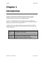
Chapter 1
Introduction
Chapter 1
Introduction
ssI15765-2 is a high performance ISO 15765-2 protocol stack written in ANSI C.
ssI15765-2 adheres to both the ISO 15765-2 specification and to the software
development best practices described in the MISRA C guidelines.
ssI15765-2 is a modularized design with an emphasis on software readability and
performance. ssI15765-2 is easy to understand and platform independent allowing it to
be used on any CPU or DSP with or without an RTOS.
ssI15765-2 implements the data link and network layer as described in ISO 15765-2.
The application layer, described in ISO 15031-5 (SAE J1979), is the responsibility of the
end user to implement.
Filenames
File Description
i15765.h
Core header file. Do not modify.
i15765.c
Core source file. Do not modify.
i15765app.h
Application header file. Modification allowed.
i15765app.c
Application source file. Modification allowed.
i15765cfg.h
Configuration header file. Modification allowed.
Table 1-1: ssI15765-2 files
ssI15765-2 User’s Manual
Page 4 of 18
Chapter 2
Integration of ssI15765
Chapter 2
Integration of ssI15765-2
This chapter describes how to integrate ssI15765-2 into your application. After this is
complete, you will be able to receive and transmit ISO 15765-2 messages over CAN. For
implementation details, please see the chapters covering the APIs for ssI15765-2 and
ssCAN.
Integration Steps:
1. Develop or purchase a CAN device driver which adheres to the CAN API specified
in Chapter 3.
2. Before using any of the ssI15765-2 module features, make sure the CAN driver
has been initialized by calling can_init(). Typically it is called shortly after poweron reset and before the application is started.
3. Before using any of the ssI15765-2 module features, make sure ssI15765-2 has
been initialized by calling i15765_init(). Typically it is called after can_init() and
before the application is started.
4. Call i15765_update at a fixed periodic interval (e.g. every 5 ms). This provides
the time base for the i15765 module. Due to OBD-II timing requirements, it is
recommended that this function be called at least every 5 ms.
5. Set I15765CFG_TICK_RATE, in i15765cfg.h, to your systems fixed periodic interval
described above in step #4. Units are in 0.1 ms. This define has a maximum
value of 250.
6. Set I15765CFG_SA to your source address.
7. As needed adjust the number and size of the multi-frame buffers.
ssI15765-2 User’s Manual
Page 5 of 18
Chapter 3
ssCAN API
Chapter 3
ssCAN API
The hardware abstraction layer (HAL) is a software module that provides functions for
receiving and transmitting controller area network (CAN) data frames. Because CAN
peripherals typically differ from one microcontroller to another, this module is
responsible for encompassing all platform depended aspects of CAN communications.
The HAL contains three functions that are responsible for initializing the CAN hardware
and handling buffered reception and transmission of CAN frames.
Function Prototype
void can_init ( void )
uint8_t can_rx ( can_t *frame )
uint8_t can_tx ( can_t *frame )
Table 3-1: HAL functions
Function Description
Initializes CAN hardware
Receives CAN frame (buffered I/O)
Transmits CAN frame (buffered I/O)
3.1 Data Type Definitions
Data type:
can_t
Description:
can_t is a data type used to store CAN frames. It contains the CAN frame
identifier, the CAN frame data, and the size of data. NOTE: If the most
significant bit of id (i.e. bit 31) is set, it indicates an extended CAN frame, else it
indicates a standard CAN frame.
Definition:
typedef struct {
uint32_t id;
uint8_t buf[8];
uint8_t buf_len;
} can_t;
ssI15765-2 User’s Manual
Page 6 of 18
Chapter 3
ssCAN API
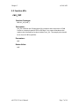
3.2 Function APIs
can_init
Function Prototype:
void can_init( void );
Description:
can_init initializes the CAN peripheral for reception and transmission of CAN
frames at a network speed of 250 or 500 kbps. Any external hardware that
needs to be initialized can be done inside of can_init. The sample point should
be as close to 0.80 as possible.
Parameters:
void
Return Value:
void
ssI15765-2 User’s Manual
Page 7 of 18
Chapter 3
ssCAN API
can_rx
Function Prototype:
uint8_t can_rx ( can_t *frame );
Description:
can_rx checks to see if there is a CAN data frame available in the receive buffer.
If one is available, it is copied into the can_t structure which is pointed to by
frame. If the most significant bit of frame->id (i.e. bit 31) is set, it indicates an
extended CAN frame, else it indicates a standard CAN frame.
Parameters:
frame: Points to memory where the received CAN frame should be stored.
Return Value:
1: No CAN frame was read from the receive buffer.
0: A CAN frame was successfully read from the receive buffer.
ssI15765-2 User’s Manual
Page 8 of 18
Chapter 3
ssCAN API
can_tx
Function Prototype:
uint8_t can_tx ( can_t *frame );
Description:
If memory is available inside of the transmit buffer, can_tx copies the memory
pointed to by frame to the transmit buffer. If transmission of CAN frames is not
currently in progress, then it will be initiated. If the most significant bit of
frame->id (i.e. bit 31) is set, it indicates an extended CAN frame, else it
indicates a standard CAN frame.
Parameters:
frame: Points to the CAN frame that should be copied to the transmit buffer.
Return Value:
1: No CAN frame was written to the transmit buffer.
0: The CAN frame was successfully written to the transmit buffer.
ssI15765-2 User’s Manual
Page 9 of 18
Chapter 4
ssI15765-2 API
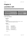
Chapter 4
ssI15765-2 API
This chapter describes the application program interface (API) for the ssI1576-2 module.
Function Prototypes
void i15765_init ( void )
void i15765_update ( void )
void i15765_tx_app ( i15765_t *msg, uint8_t *status )
void i15765app_process ( i15765_t *msg)
Table 4-1: API functions
Function Descriptions
Initializes protocol stack
Provides periodic time base
Transmits a 15765 message
Processes a received 15765 messages.
4.1 Data Type Definitions
Data type:
i15765_t
Description:
i15765_t is a data type used to describe ISO 15765-2 messages. It contains
address information, data, message size, and priority.
Definition:
typedef struct {
uint8_t sa;
uint8_t ta;
uint8_t ae;
uint8_t tat;
uint8_t pri;
uint8_t *buf;
uint16_t buf_len;
/* source address */
/* target address */
/* address extension */
/* target address type */
/* priority of message */
/* pointer to data */
/* size of data (in bytes) */
} i15765_t;
ssI15765-2 User’s Manual
Page 10 of 18
Chapter 4
ssI15765-2 API
4.2 Function APIs
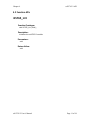
i15765_init
Function Prototype:
void i15765_init ( void );
Description:
Initializes the ssI15765-2 module.
Parameters:
void
Return Value:
void
ssI15765-2 User’s Manual
Page 11 of 18
Chapter 4
ssI15765-2 API
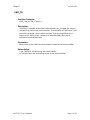
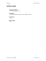
i15765_update
Function Prototype:
void i15765_update ( void );
Description:
Provides the periodic time base for the ssI15765-2 module.
Parameters:
void
Return Value:
void
ssI15765-2 User’s Manual
Page 12 of 18
Chapter 4
ssI15765-2 API
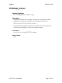
i15765app_process
Function Prototype:
void i15765app_process ( i15765_t *msg );
Description:
Processes received 15765-2 messages. This function is called by the I15765
module with a complete message and is the intended location for the
application layer to handle received messages.
For multi-frame messages this function isn’t called until all frames have been
received and assembled into a valid and complete message.
Parameters:
msg: Pointer to received ISO 15765-2 message.
Return Value:
void
ssI15765-2 User’s Manual
Page 13 of 18
Chapter 4
ssI15765-2 API
i15765_tx_app
Function Prototype:
void i15765_tx_app ( i15765_t *msg, uint8_t *status );
Description:
Used by the application layer to buffer a message for transmission. If the
application layer is interested in the status of the message, status should point
to a location in the application RAM.
For single frame messages, *status will immediately be set to either
I15765_SENT or I15765_FAILED.
For a multi-frame message, which was successfully buffered, *status will
immediately be set to I15765_SENDING. Upon completion or timeout of
message, *status will be set to I15765_SENT or I15765_FAILED. No retries will
be attempted.
For a multi-frame message, which was not successfully buffered, *status will
immediately be set to I15765_FAILED.
Parameters:
msg: The message to be transmitted.
status: Pointer to application RAM.
Return Value
void
ssI15765-2 User’s Manual
Page 14 of 18
Chapter 5
Configuration
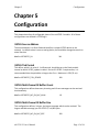
Chapter 5
Configuration
This chapter describes all configurable items of the ssI15765-2 module. All of these
configurations are defined in i15765cfg.h.
I15765 Source Address
The source address is an 8-bit field and identifies a unique I15765 device on the
network. Its default value is set as a testing device, but should be changed to match its
actual function.
#define I15765CFG_SA
241
I15765 Tick Period
This define, which is in units of .1 milliseconds, should be set to the fixed periodic
interval at which i15765_update is called. Due to ISO 15765-2 requirements, it is
recommended that the period be no larger than 5 ms. Maximum is 250 (25 ms).
#define I15765CFG_TICK_PERIOD
100
I15765 Multi-frame RX Buffer Count
This configuration defines how many incoming multi-frame messages can be received
simultaneously.
#define I15765CFG_MF_RX_BUF_NUM
10
I15765 Multi-frame RX Buffer Size
This configuration defines, in bytes, the largest message which can be received. The
largest available message, per ISO 15765-2, is 4,095 bytes.
#define I15765CFG_MF_RX_BUF_SIZE
ssI15765-2 User’s Manual
100
Page 15 of 18
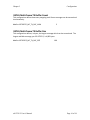
Chapter 5
Configuration
I15765 Multi-frame TX Buffer Count
This configuration defines how many outgoing multi-frame messages can be transmitted
simultaneously.
#define I15765CFG_MF_TX_BUF_NUM
3
I15765 Multi-frame TX Buffer Size
This configuration defines, in bytes, the largest message which can be transmitted. The
largest available message, per ISO 15765-2, is 4,095 bytes.
#define I15765CFG_MF_TX_BUF_SIZE
ssI15765-2 User’s Manual
100
Page 16 of 18
Chapter 6
Examples
Chapter 6
Examples
This chapter gives examples of how to receive/decode and transmit ISO 15765-2
messages. For details on application layer messages, see ISO 15031-5 or its SAE
equivalent J1979.
6.1 Receive and Decode ISO 15765-2 Messages Example:
void
i15765app_process ( i15765_t *msg ) {
switch( msg->buf[0] ) {
/* powertrain diagnostic response SID */
case 0x41: {
/* is it the supported PID response? */
if( msg->buf[1] == 0 ) {
printf("byte a\n", msg->buf[2]);
printf("byte b\n", msg->buf[3]);
printf("byte c\n", msg->buf[4]);
printf("byte d\n", msg->buf[5]);
}
break;
}
/* add other messages here */
case XXX: {
}
}
}
ssI15765-2 User’s Manual
Page 17 of 18
Chapter 6
Examples
6.2 Transmit I15765-2 Message Example:
/*
** Transmit a powertrain request message.
*/
void
i15765app_req_pids ( void ) {
i15765_t msg;
uint8_t buf[8];
/* basic stuff */
msg.buf = buf;
msg.pri = 6;
/* functional request msg */
msg.ta = 0x33;
/* normal functional target address */
msg.tat = I15765_TAT_NF;
/* request supported PIDs (0-20) */
buf[0] = 1;
buf[1] = 0;
msg.buf_len = 2;
/* transmit message */
i15765_tx_app( &msg, &status_rq );
/* it's a single frame, so status has been updated */
if( status_rq == I15765_SENT )
printf("Message transmitted\n");
else
printf("Message not transmitted\n");
}
ssI15765-2 User’s Manual
Page 18 of 18