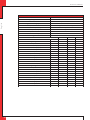
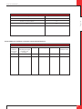
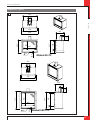
1
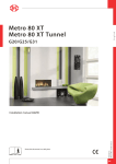
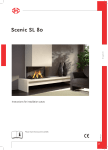
English
Global 55 CF
Global 55XT CF
G20/G25/G25.3 (Natural gas) G31 (Propane)
Store this document in a safe place
956.000.00.UK
DRU15798-585944-EN--0914-2
Installation manual (UK/IE)
UK
INSTAL L ATIO N MA N U A L
Contents
English
1. Introduction
2. CE declaration
3. SAFETY
3.1 General
3.2 Regulations
3.3 Precautions/safety instructions during installation
3.4 Second thermocouple safety
3.5 Oxypilot safety
4. Removing the packaging
5. Installation
5.1 Type of gas
5.1.1 Reconstruction to different type of gas
5.2 Connection
5.2.1 Gas connection
5.2.2 Electric connection
5.3 Placing the appliance
5.4 Placing a built-in appliance
5.5 Placing the chimney breast
5.6 Placing the control hatch
5.7 Flue gas discharge system in appliances with open combustion
5.7.1 General
5.7.2 Connection flue gas discharge system
5.8 Flue gas discharge / combustion air supply system in appliances with closed combustion
5.8.1 General
5.8.2 Construction of the concentric system
5.8.3 Placing the concentric system
5.8.4 Connection existing chimney
5.9 Additional instructions
5.10 Placing the appliance
5.10.1 Connecting the appliance
5.10.2 Connecting the flue gas discharge system
5.11 Setting the appliance
5.12 Glass pane
5.12.1 Removing the glass pane
5.12.2 Placing the glass pane
5.13 Placing the wood set
5.14 Placing / replacing the receiver’s batteries
6. Control
6.1 Connecting the receiver
6.1.1 Connecting the receiver
6.1.2 Placing / replacing the receiver's batteries
6.2 Setting the communication code
6.3 Alternative operation
7. Final inspection
7.1 Gastightness
7.2 Gas pressure/line-pressure
7.3 Ignition pilot and main burner
7.3.1 First ignition of the appliance after installation or adjustments
7.3.2 Main burner
7.4 Flame picture
8. Maintenance
8.1 Parts
9. Delivery
10. Malfunctions
Appendix 1 Diagnosis of malfunctions
Appendix 2 Various tables
Appendix 3 Figures
UK
INST AL L AT I ON M AN U A L
1. Introduction
English
DRU, a manufacturer of gas-fired heating appliances, develops and produces products that comply with the
highest quality, performance and safety requirements. This appliance has a CE label, which means that it complies
with the essential requirements of the European gas appliance directive. The appliance is supplied with an
installation manual and a user manual. As an installer, you must be certified and competent in the field of gas-fired
heating. The installation manual will give you the information you need to install the appliance in such a way that
it will operate properly and safely.
This manual discusses the installation of the appliance and the regulations that apply to the installation. In
addition, you will find the appliance’s technical data as well as information on maintenance, possible malfunctions
that might occur and what may cause them.
The figures can be found at the back of this booklet, in the appendix.
Please, read and use this installation manual carefully and completely, prior to installing this appliance. If you use
the DRU Powervent system® or the DRU Smartvent system®, you must carefully and fully read and use the
accompanying installation manual as well, prior to its installation.
The following symbols are used in the manual to indicate important information:
Work to be performed
!Tip
Suggestions and recommendations
!Caution You will need these instructions to prevent problems that might occur during installation and/or use.
!Caution You need these instructions to prevent fire, personal injury or other serious damages.
Ø
After delivery, you should give the manuals to the user.
2. CE declaration
We hereby declare, that the design and construction method of the gas-fired heating appliance issued by Dru
complies with the essential requirements of the gas appliance directive.
Product:
Type:
EEC directives:
Standards:
gas-fired heating appliance
Global 55 CF / Global 55XT CF
2009/142/EC
NEN-EN-613
NEN-EN-613/A1
Internal precautions at the company will guarantee that appliances produced in series comply with the essential
requirements of the EC directives in force and the standards derived from them.
This declaration will lose its validity if adjustments are made to the appliance, without prior written permission by
DRU.
You will be able to download a copy of the test certificate via www.druservice.com.
M.J.M. Gelten
General manager
Postbus 1021, 6920 BA Duiven
Ratio 8, 6921 RW Duiven
www.dru.nl
UK
INSTAL L ATIO N MA N U A L
3. SAFETY
3.1 General
!Caution -
-
Please observe the generally applicable regulations and precautions/safety instruction in this manual.
First check the exact technical version of the appliance to be installed in Appendix 2, Table 2.
3.2 Regulations
English
Please install the appliance in accordance with the applicable national, local and constructional (installation)
regulations.
3.3 Precautions / safety instructions during installation
Ø
Ø
Ø
Ø
Ø
Ø
Ø
Ø
Ø
Ø
Ø
Ø
Ø
Ø
Ø
Ø
Carefully observe the following precautions/safety regulations:
You should only install and maintain the appliance if you are a certified and competent installer in the field of
gas-fired heating;
Do not make any changes to the appliance;
If you are installing an appliance that must be built in;
use non combustible and heat-resistant material for the chimney breast, including the top of the chimney
breast, the material inside the chimney breast and the back wall against which the appliance will be placed.
For this you can use both sheet material and stone-like materials;
take sufficient measures to prevent high temperatures of the wall behind the chimney breast, including the
materials and/or objects that are behind the wall;
comply with the minimum required internal measurements of the chimney breast;
vent the chimney breast by means of ventilation holes with a combined passage as stated further down in
the text. When placing an appliance with open combustion (type B 11 AS/BS), no chimney breast ventilation is
required, as there is an existing chimney with a brickwork fireplace that is sufficiently able to absorb the heat;
use heat-resistant electric connections and make sure that they do not make contact with the appliance;
If you are installing an appliance with open combustion: please use a suitable flue gas discharge system provided
with the CE label, and make sure there is sufficient ventilation of the room where the appliance is installed,
according to legislation.
if you are installing an appliance with a closed combustion: only use the concentric systems supplied by DRU;
if you are installing a free-standing appliance:
place the appliance away from the back wall by the minimum distance stated further down in the text;
make sure you observe the minimum distance in relation to the side wall(s) and the space above the
appliance (see Appendix 3, fig. 2).
do not cover the appliance and/or do not wrap it in an insulation blanket or any other material;
make sure that combustible objects and/or materials have a distance from the appliance of at least 500 mm
only use the accompanying wood/pebble set and place it exactly as described;
the space surrounding the pilot burner, 2nd thermocouple or ionisation pins must remain free;
make sure there is no dirt in gas pipes and connections;
place a gas tap in accordance with applicable regulations;
prior to putting into operation, check the complete installation for gastightness;
if your appliance is provided with explosion hatches on its top, you must make sure that they cannot be blocked
and check whether they fit well onto the sealing surface, prior to building in the appliance;
do not ignite the appliance before the gas and discharge connections have been fully installed, first observe the
procedure described in chapter 7.3.
replace broken or torn glass panes.
!Caution In case of broken or torn glass panes, the application may not be used.
3.4 Second thermocouple safety (if applicable, see Appendix 2, Table 2)
It is possible, that the appliance to be installed has 2 thermocouples. Thermocouple 1 is always next to the pilot
burner, thermocouple 2 is always elsewhere above the main burner.
If the appliance is provided with a second thermocouple safety on the main burner, you need to know that it will
intervene if no proper transfer has taken place from the pilot burner to the main burner or from the main burner
itself. The gas supply will be interrupted after 22 seconds. In order to solve a poor or non-existent transfer from the
pilot burner to the main burner, please use the malfunction search diagram in Appendix 1.
UK
INST AL L AT I ON M AN U A L
3.5 Oxypilot safety (if applicable, see Appendix 2, Table 2)
4.
Ø
Ø
Ø
Ø
Ø
Ø
English
If the appliance is provided with an oxypilot safety, you need to know that it will intervene (the pilot flame and the
gas supply to the main burner will be switched off) if insufficient combustion air (oxygen) is supplied and/or if the
discharge system has insufficient thermal draught.
Once the supply of combustion air is sufficient again, the appliance can be restarted.
The supply of fresh air can be controlled by installing/opening ventilation holes in the room where the appliance
is installed.
Removing the packaging
Note the following items when removing the packaging:
Remove all packaging materials.
Remove all supplied components in, on and/or at the appliance.
Check the appliance and accessories for damages (during transport).
If necessary, contact your supplier.
Never install an appliance that is damaged !
Remove any screws that are used to fix the appliance to a platform or pallet.
!Caution Heat-resistant glass is a ceramic material. Very small irregularities in the glass pane(s) cannot be avoided, but are
within the required quality standards.
!Caution Keep plastic bags away from children.
Ø
Ø
5.
In Appendix 2, Table 1 you can see which parts you should have after removing the packaging.
Contact your supplier if you do not have all the parts after you finished removing the packaging.
Dispose of packaging in accordance with local regulations.
Installation
Read this manual carefully to ensure the proper and safe installation of the appliance.
!Caution Install the appliance in the order described in this chapter.
Ø
Ø
Please install the appliance in accordance with the applicable national, local and constructional (installation)
regulations.
Observe the regulations/instructions in this manual.
5.1 Type of gas
The data plate indicates for which type of gas, gas pressure and for which country this appliance is intended.
The data plate can be found on the appliance or can be attached to a chain to which it should remain attached.
!Caution Check whether the appliance is suitable for the type of gas and the gas pressure used at the location.
5.1.1 Reconstruction to different type of gas
If you want to convert this appliance into a different type of gas, please contact DRU's service department and ask
what is possible. Reconstructions should only be performed by authorized gas installers.
5.2 Connection
5.2.1 Gas connection
Place a gas tap in the gas pipe in accordance with the applicable regulations.
!Caution Make sure there is no dirt in gas pipes and connections;
The following requirements apply to the gas connection:
use a gas pipe with the correct dimensions, so that no pressure loss can occur;
the gas tap must be approved (in the EU this will be the CE mark);
you should always be able to reach the gas tap.
UK
INSTAL L ATIO N MA N U A L
5.2.2 Electric connection
English
In case of a 230 Volt electrical connection, provide proper grounding, if applicable.
Place this electrical connection away from the appliance, as low as possible in the chmney breast.
This has to do with the temperature development in the chimney breast.
If possible, place the receiver after any building work has been completed.
If this is not possible:
!Caution Protect the receiver against dust and moisture created during the building process!
5.3 Placing the appliance
!Caution -
Always place the appliance with a minimum distance of 500 mm from combustible objects or materials;
Place the discharge pipes in such a way that situations with risk of fire can never occur;
Always place the appliance in front of a wall of non combustible and heat-resistant material;
Always maintain a minimum distance between appliance and back wall, if indicated in the dimensional
drawing (Appendix 3, fig. 2);
Take sufficient measures to prevent high temperatures of a possible wall behind the chimney breast,
including the materials and/or objects that are behind the wall;
Do not cover the appliance and/or do not wrap it in an insulation blanket or any other material;
Make sure that the appliance to be installed has a stable position. Attach the appliance, if applicable, to the
wall using the wall brackets and/or fasten the extending legs with self-tapping screws.
!Caution When installing an appliance that has to be built in, take the following into account:
The minimum construction dimensions according to Appendix 3, fig. 1 and 2.
-
Ø
Ø
Provide a gas connection at the location. For details (see section 5.2).
Make a passage for the flue gas discharge system or the concentric system with the following diameters; for
details, see section 5.7 or 5.8:
the pipe diameter +10 mm for a passage through non combustible material;
the pipe diameter +100 mm for a passage through combustible material.
!Caution Starting at section 5.9, you will find additional instructions that are specifically needed for the installation of your
appliance.
5.4 Placing a built in appliance (if applicable)
Not all DRU built in appliances are supplied with a control hatch. If not included in the delivery, this control hatch
is available separately. In case of appliances with closed combustion (type C11/C31) we always recommend using
the Dru control hatch. In case of appliances with open combustion (type B11 AS/BS), a control hatch is not required.
In this section we assume an application with control hatch.
!Caution If you do not use a recommended Dru control hatch, please strictly observe the safeguards and necessary
instructions stated in chapters 5.4 to 5.6.
If you are not using the control hatch, please take the following into account as well:
the accessibility of components that are normally placed in the control hatch;
the maximum temperature of these components (maximum 55 °C).
The gas control is mounted under the appliance, at the burner mounting plate. It must be taken out and placed in
the control hatch at a later time. For placing the gas control in the control hatch, see section 5.6.
Ø
Follow the procedure described below:
Disconnect the pipes from the gas control (flexible gas pipe, aluminium pilot burner pipe and thermocouple 1);
!Caution The red wire of thermocouple 2, if applicable, must remain connected to the gas control.
Ø
Ø
Ø
Disconnect the gas control from the burner mounting plate by unscrewing the self-tapping screw.
Carefully unwind the red and black wire of thermocouple 2, if applicable.
Carefully lay the gas control together with the wires of thermocouple 2, the ignition cable, the flexible gas hose,
the aluminium pilot burner pipe and the type plate plus chain in the direction of the control hatch.
!Caution -
-
UK
Prevent dirt in gas pipes and connections;
Avoid kinks in the pipes.
INST AL L AT I ON M AN U A L
-
Make sure the ignition cable cannot come into contact with other wires;
The data plate should remain attached to the chain.
Ø
Ø
Set the height of the appliance using the adjustable feet (if applicable).
Make the appliance level at the same time.
!Tip
The construction frame for most 2 or 3 sided appliances can be adjusted. This will allow you to connect the
construction frame to the chimney breast correctly. For 2 or 3 sided appliances that cannot be adjusted, we would
like to refer you to chapter 5.9 'Additional instructions'.
English
!Caution -
!Caution do not ignite the appliance before the gas and discharge connections have been fully installed, first observe the
procedure described in chapter 7.3.
5.5 Placing the chimney breast (if applicable)
In order to provide proper heat discharge, there should be sufficient space around the appliance. The chimney
breast should be ventilated sufficiently by means of ventilation holes (incoming and outgoing).
!Caution -
-
Use non combustible and heat-resistant material for the chimney breast, including the top of the chimney
breast, the material inside the chimney breast and the back wall of the chimney breast;
Make sure that the appliance is not carrying the weight of the chimney breast when using stone-like
materials;
The passage of the ventilation holes (outgoing), which are placed as high as possible, is stated in Appendix 2,
Table 2.
!Caution When placing the chimney breast, you should take the following into account (see Appendix 3, fig. 2):
-
-
the location of the control hatch: this must be placed as low as possible;
the dimensions of the control hatch; see Placing the control hatch section 5.6;
the Dru control hatch is not supplied with all appliances. Nevertheless, we recommend only using a Dru
control hatch, if available, exept in the case of B11 AS/BS appliances. If you decide not to take this option, you
will have to make a 100 cm2 ventilation hole that is placed as low as possible, for the benefit of the incoming
ventilation.
the location of the ventilation holes (V) (outgoing);
maintain a minimum 30 cm distance between the top of the ventilation hole (outgoing) and the ceiling of
the house.
the measurements of the glass pane, so that it can be placed/removed after placing the chimney breast;
the protection of the gas control and the pipes against cement and plaster.
If possible, you should place decorative strips, frames, etc., after any required structural work has been
completed. Avoid the use of painter's tape. If this is not possible: please use good quality painter's tape and
remove it immediately after plastering or painting work has been completed.
!Tip
You should preferably apply the ventilation holes (outgoing) on both sides of the chimney breast. You can use
DRU ventilation elements.
Prior to completely closing the chimney breast, check whether the discharge / concentric system is placed
correctly.
whether the channels, fixing brackets and possible clip bindings, which cannot be reached after installation,
are fastened by means of self-tapping screws.
Ø
If applicable, do not plaster on or over the edges of the construction frame, because:
the heat of the appliance could cause cracks;
it will no longer be possible to remove/place the glass pane.
When using stone-like materials and/or a plaster finishing, allow the chimney breast to dry for at least six weeks
prior to using the appliance in order to prevent cracks.
Ø
UK
INSTAL L ATIO N MA N U A L
5.6 Placing the control hatch (if applicable)
The control hatch (also see paragraphs 5.4 and 5.5) is placed as low as possible in the chimney breast.
!Caution -
-
The bottom of the control hatch may not be placed higher in the appliance than the burner surface.
Place control hatch and bracket with gas control and accessories indoors in a dry place only!
English
A number of components are placed in the control hatch, such as data plate, gas control, receiver belonging to the
remote control and, if applicable, the components belonging to the DRU Powervent system®.
Ø
Ø
Place the control hatch as follows; see Appendix 3, fig. 3 for details:
Make an opening in the chimney breast, as described in the manual for the control hatch.
Place the inner frame (1); unscrew bolts (5) for this.
!Tip
-
Ø
Ø
Ø
Mount the gas control to the brackets of the inner frame (2).
Check whether pipes and connections are free from dirt;
Reconnect the pipes to the gas control.
!Caution -
-
When the chimney breast is made of bricks, the inner frame can be built with bricks at the same time
When using a different material, you can glue the inner frame or fix it with four flush screws.
Avoid kinks in the pipes;
Tighten the flexible gas pipe and the pilot burner pipe until they are gastight.
First tighten the thermocouple by hand and;
Then tighten it a quarter turn using a suitable spanner;
The pilot burner pipe must be protected against possible corrosive influences as a result of, for example,
humidity, cement that has fallen down, dirt that has fallen down from the chimney, etc. The pilot burner pipe
should remain permanently free from the ground and the walls of the room in which the appliance is built in.
When installing in an existing fireplace, or if it is not possible to keep the pipes free, the pipe should be
protected against corrosion by means of a jacket.
Ø
Ø
Ø
Ø
Ø
Ø
Prevent dirt in gas pipes and connections.
Connect the gas pipe to the gas tap.
Bleed the gas pipe.
Place the receiver in the holder (3); for connecting, see section 6.1.
Place the data plate in its intended clamp (6).
Fix the outer frame with door (4) to the inner frame using 2 socket cap screws (5).
!Tip
You can place the outer frame in such a way, that the door turns to the left or to the right.
5.7 Flue gas discharge system in appliances with open combustion
For connection to an existing chimney without a discharge pipe or flexible SS discharge – only allowed in Great
Britain – the instructions provided in the separately supplied booklet 'Fitting into a conventional class 1 chimney'
apply. In addition to the installation instructions, this booklet also contains supplementary tests. In this situation
we recommend using a stainless steel flexible discharge pipe over the complete length, with a draught increasing
hood.
5.7.1 General
The connection dimensions and the minimum length of the discharge system are indicated in Annex 2, table 2.
The appliance should be connected in accordance with the applicable national, local and constructional
(installation) regulations. You should only install the appliance in a well ventilated room which complies with the
applicable national, local and constructional (installation) regulations, in order to guarantee sufficient air supply.
!Caution -
-
UK
When the appliance is installed in a house with a mechanical air extraction system and/or an open kitchen
with cooker hood, you will need a permanent ventilation hole in the room where the appliance is installed;
please observe the gas installation regulations and the local regulations for dimensions and other required
provisions.
No ventilation of the chimney breast is required in case of an existing chimney with a masonry fireplace that
is sufficiently able to absorb the heat. Therefore the ventilation hole in the chimney breast does not apply to
the class 1 chimney in the UK.
INST AL L AT I ON M AN U A L
5.7.2 Connection of flue gas discharge system (if a class 1 chimney is not applicable)
For connection to an existing chimney, a flexible stainless steel discharge pipe is required over the complete
length for the discharge of the flue gases, unless indicated otherwise. A draught increasing hood is recommended
here.
!Caution -
Prevent dirt from an existing chimney from entering the flue gas discharge.
Prevent false draught by carefully closing the space between the existing chimney and the discharge
material.
Bends of more than 45 degrees are not allowed in the flue gas discharge system, unless indicated otherwise.
Maintain a distance of at least 50 mm between the outside of the concentric system and the walls and/or
ceiling. If the system is built in (for instance) a cove, it should be made with non combustible material all
around it;
Use heat-resistant insulation material when passing through combustible material.
Use a flue gas discharge system with the correct diameter, and which is provided with the CE mark.
!Caution Some heat-resistant insulation materials contain volatile components that will spread an unpleasant smell during
a longer period; these are not suitable.
Ø
English
-
Place the flue gas discharge system as follows:
Connect the pipe pieces or flexible SS discharge.
!Caution -
-
Make sure that the right insertion length is maintained.
Secure the connections on locations that are impossible to reach after installation by means of self-tapping
screws.
5.8 Flue gas discharge / combustion air supply system in appliances with closed
combustion
5.8.1 General
The appliance's type of discharge system is stated in Appendix 2, Table 2.
The appliance will be connected to a combined flue gas discharge / combustion air supply system, hereafter to be
referred to as the concentric system.
The passage to the outside can be made with both a wall terminal and roof terminal. If necessary, you can also use
an existing chimney (see section 5.8.4).
!Caution -
-
Only use the concentric system supplied by DRU This system has been tested in combination with the
appliance. DRU cannot guarantee a proper and safe operation of other systems and does not accept any
responsibility or liability for this;
For connecting to an existing chimney you should only use the chimney kit supplied by DRU.
The concentric system is constructed from (the flue spigot of) the appliance.
If, due to constructional circumstances, the concentric system is placed first, it is possible to connect the appliance
by means of a telescopic pipe piece.
5.8.2 Construction of the concentric system
Depending on the construction of the concentric system, the appliance will have to be further adjusted with
possibly a restrictor slide or air inlet guide.
See Tables 4 and 6 for determining the correct adjustment and section 'Adjustment of the appliance' for the
method of working.
The concentric system with wall or roof terminal has to comply with the following conditions:
In appendix 2, table 4 or 5 you can find whether a concentric pipe should be connected and what the
minimum vertical length would have to be.
Determine the permissibility of the required discharge.
When using a wall terminal, the following applies:
The total vertical pipe length, when using a wall terminal, may have a maximum length that you can find in
Appendix 2, Table 4.
The minimum vertical pipe length, when using a wall terminal, can be found in appendix 2, table 4.
The total horizontal pipe length, when using a wall terminal, may have a maximum length that you can find
in Appendix 2, Table 4 (without wall terminal; see Appendix 3, fig. 4).
UK
INSTAL L ATIO N MA N U A L
When using a roof terminal, the following applies:
The construction of the chosen system, when using a roof terminal, must be permissible according to
Appendix 2, Table 5. (See the method of working described below)
English
The working method below indicates how the permissibility is determined of a concentric system when using a
roof terminal.
1) Count the number of 45° and 90° bends required
2) Count the total number of whole metres of horizontal pipe length;
3) Count the total number of metres of vertical and/or sloping pipe length (roof terminal excluded).
4) In the first 2 columns of Table 5, look for the number of bends required and the total horizontal pipe length.
5) In the top row of Table 5, look for the required total vertical and/or sloping pipe length.
6) If you end up in a box with a letter, the concentric system chosen by you is permissible.
7) Use Table 6 to determine how the appliance should be adjusted
5.8.3 Placing the concentric system
!Caution -
-
Maintain a distance of at least 50 mm between the outside of the concentric system and the walls and /or
ceiling. If the system is built in (for instance) a cove, it should be made with non combustible material all
around it;
Use heat-resistant insulation material when passing through combustible material;
The rosette of the wall terminal is too small to seal the opening when passing through combustible material.
That is why you should first apply a sufficiently large heat-resistant intermediate sheet to the wall. Then, the
rosette is mounted on the intermediate sheet.
The roof terminal can end in a sloping and a flat roof.
The roof terminal can be supplied with a glue plate for a flat roof or with a universally adaptable tile for a sloping
roof.
!Caution Some heat-resistant insulation materials contain volatile components that will spread an unpleasant smell during
a longer period; these are not suitable.
Ø
Ø
Ø
Ø
Ø
Ø
Ø
Ø
Place the concentric system as follows:
Build the system up from (the flue spigot of) the appliance.
Connect the concentric pipe pieces and, if necessary, the bend(s).
On each connection, apply a clip binding with silicon sealing ring.
Use a self-tapping screw to fix the clip binding to the pipe on locations that cannot be reached after installation.
Apply sufficient wall brackets, so that the weight of the pipes does not rest on the appliance.
Attach the wall terminal from the outside by means of four screws.
Determine the remaining length for the wall or roof terminal and cut it to size, make sure the correct insertion
length is maintained.
Place the wall terminal with the (groove/folded) seam at the top;
!Caution -
UK
When using the wall terminal, place the terminal with a downward slope of 1 cm / metre towards the
outside, in order to prevent rain water from raining in.
INST AL L AT I ON M AN U A L
5.8.4 Connection to an existing chimney
It is possible to connect the appliance to an existing chimney.
A flexible SS pipe is placed in the chimney with a fitting diameter at the flue gas discharge pipe, for the discharge
of flue gas. The surrounding space is used to supply combustion air.
English
The following requirements apply when connecting to an existing chimney:
only allowed when used in combination with the special DRU chimney kit. The installation regulation is also
supplied;
the internal dimensions should be at least 150 x 150 mm;
the vertical length has a maximum of 12 metres;
the total horizontal pipe length may have a maximum length that you can find in Appendix 2, Table 4;
the existing chimney has to be clean;
the existing chimney has to be tight.
For adjusting the appliance, the same conditions/instructions apply as for the concentric system described above.
UK
INSTAL L ATIO N MA N U A L
5.9 Additional instructions
This appliance has been provided with an on/off switch. This switch can be used at all times to switch off the
appliance (see Appendix 3, fig. 43b).
!Caution Check whether the on/of switch is set to the 'on' position to start up the appliance.
5.10 Placing the appliance
!Caution -
English
-
Place the appliance on non combustible and heat-resistant material.
Place the appliance in a chimney breast or existing fireplace (also see sections 5.4, 5.5 and 5.7), use non
combustible and heat-resistant material.
Use heat-resistant finishing materials such as plastering material around the appliance
(see Appendix 3, fig. 45 (A));
If the built-in appliance is less than 150mm above the floor, you should provide non combustible and
heat-resistant material in front of the appliance (see Appendix 3, fig. 45 (B)).
Keep a minimum 15 mm distance between the appliance and the back and side walls.
Place the appliance as follows:
Paste the sealing tape on the edge of the appliance (see Appendix 3, fig. 2 (B)), this will reduce the transfer of heat
from the appliance to the chimney breast. A high temperature of the chimney breast will cause cracks;
Ø
Determine the location of the appliance, taking into account the dimensions of the appliance and the free space
around the appliance (see Appendix 3, fig. 1 and 2);
Ø
Determine the construction height of the appliance;
Ø
If necessary, adjust the appliance and connect the flue gas discharge system (see sections 5.10.2 and 5.11);
Ø
Provide a gas connection on site (see sections 5.2 and 5.10.1);
Ø
Create a roof terminal for the flue gas discharge system with the following diameter (see section 5.7);
110 mm for a roof terminal through non combustible material,
200 mm for a roof terminal through combustible material.
Ø
Level the appliance on its destined location;
Ø
Fasten the appliance, using the holes in the flange at the front;
Ø
Remove the glass pane (see section 5.12.1);
Ø
Connect the appliance (see section 5.10.1);
!Caution Do not ignite the appliance until it is fully installed.
Ø
Place the wood set (see section 5.13);
Ø
Place the glass pane (see section 5.12.2).
Ø
5.10.1 Connecting the appliance
Connect the gas pipe to the gas tap under the burner mounting plate, proceed as follows:
Remove the vermiculite tray from the appliance (see Appendix 3, fig. 10);
Remove the profile from the front of the combustion chamber by removing the screws and taking out the profile
(see Appendix 3, fig. 11);
Ø
Remove the self-tapping screws from the burner mounting plate and remove the burner mounting plate plus
accessories from the appliance (see Appendix 3, fig. 12);
Ø
Cut a cross in the centre of the grommet to allow the gas supply pipe to pass through;
Ø
Create a gas supply through the grommet. Later on, a gas tap will be connected to this (see Appendix 3, fig. 13);
Ø
If necessary, blow clean the gas pipe;
Ø
Disconnect the gas tap from the burner plus accessories and connect it to the gas supply;
!Caution Make sure the grommets are mounted properly, so that they provide a good seal.
!Tip
Make sure the gas tap is at 45°, so that the tap can be easily closed during maintenance. The tap will then be
within reach by removing the service plate under the vermiculite tray.
!Caution It is also necessary to place a gas tap outside of the appliance (see section 5.2.1).
Ø
Place the burner mounting plate plus accessories back in the appliance and fasten it with the self-tapping screws;
Ø
Remove the service plate by removing the self-tapping screw and taking out the plate;
Ø
Connect the pipe of the burner plus accessories to the gas tap under the burner mounting plate;
Ø
Bleed the gas pipe;
Ø
Check gas tightness (see section 7.1);
Ø
Check line-pressure (see section 7.2);
Ø
Place back the service plate and fasten it with the self-tapping screws;
Ø
Place the batteries in the battery holder and place the holder in the intended bracket (see section 5.14);
Ø
Connect the receiver and place it in the intended holder (see section 6.1 and Appendix 3, fig.13);
Ø
Set the communication code between receiver and remote control (see section 6.2).
Ø
Ø
UK
INST AL L AT I ON M AN U A L
!Caution Do not ignite the appliance until it is fully installed.
Ø
Ø
Place the profile back in the appliance and fasten it with the self-tapping screws;
Place the vermiculite tray back in the appliance.
!Caution Position the vermiculite tray correctly by means of the stop edges (as far as possible to the front).
5.10.2 Connecting the flue gas discharge system
Ø
Ø
Ø
Ø
In case of a newly to be constructed chimney breast (see section 5.7):
Connect the pipe pieces or the flexible stainless steel discharge pipe.
In case of an existing fireplace (see section 5.7):
In case of an existing fireplace plus chimney, the flexible stainless steel discharge pipe can be connected from the
inside:
Remove the self-tapping screws from the sealing plate and remove this plate from the appliance
(see Appendix 3, fig. 14);
Remove the self-tapping screws that are used to fasten the flue spigot and remove the flue spigot via the top of
the appliance (see Appendix 3, fig. 15);
Connect the flexible stainless steel discharge pipe to the flue spigot and place it back in the appliance with the
self-tapping screws;
Place the sealing plate back in the appliance and fasten it with the self-tapping screws.
English
Ø
5.11 Setting the appliance
The appliance has to be set in such a way that it works correctly in combination with the used concentric system.
!Caution In case of a flue gas discharge system that is shorter than 6 metres, the restrictor in the flue spigot must be
adapted (see Appendix 2, tables 5 and 6):
Remove the restrictor from the flue spigot (see Appendix 3, fig. 16 (R));
Break the small ring (A) from the restrictor by moving it back and forth until it comes off. A large passage will
remain (B);
!Caution Do not deform the ring, the restrictor should be flat.
Ø
Place the restrictor back in the flue spigot.
Ø
Ø
5.12 Glass pane
Avoid damaging the pane during removal/placing.
5.12.1 Removing the glass pane
Observe the following actions to remove the glass pane (see Appendix 3, fig. 5 to 9):
Remove the self-tapping screw of the vertical decorative strip and remove the decorative strip by tilting it
sideways at the top and lifting it out, do the same at the other side;
Ø
Remove the lower decorative strip by grabbing it in the groove and lifting it out;
Ø
Remove the central self-tapping screw from the upper glass strip and remove the glass strip;
Ø
Tilt the glass pane from the top, away from the appliance;
!Caution Prevent the glass pane from making an angle that is too large and could damage the glass pane.
Ø
Grab the glass pane at both sides and remove the glass pane;
Ø
Store the glass pane on a safe place.
Ø
5.12.2 Placing the glass pane
Ø
Ø
Ø
Place the glass pane at the bottom of the holders;
Tilt the glass pane from the top, against the appliance;
Place the central glass strip and fasten it in the middle by means of a self-tapping screw;
!Caution Avoid/remove finger prints on the glass pane, as they will burn into the glass.
Ø
Place back the lower decorative strip;
Ø
Place back the vertical decorative strips and fasten them with the self-tapping screws.
UK
INSTAL L ATIO N MA N U A L
5.13 Placing the wood set
The appliance is supplied with a wood set.
!Caution Strictly observe the following instructions to prevent unsafe situations:
English
-
Only ever use the supplied wood set;
Place the wood set exactly as described;
Make sure the pilot burner and the surrounding space remain free (see Appendix 3, fig. 17);
Make sure the 2nd thermocouple and the surrounding space remain free (see Appendix 3, fig. 18).
The wood set consists of a number of logs, black chips (see Appendix 3, fig. 19) and glow material
(see Appendix 3, fig. 20).
Ø
Identify logs A to C (see Appendix 3, fig. 21);
!Tip
Use the burn stains on the logs for identification.
Ø
Place log A at the back of the appliance, use the positioning cams and distribute part of the chips
(see Appendix 3, fig. 22)
Ø
Place log B on the appropriate bracket (see Appendix 3, fig. 23).
Ø
Place log C in the appliance, use the positioning cams (see Appendix 3, fig. 24).
Ø
Fill the vermiculite tray with chips; evenly distribute the chips;
!Caution Do not place chips on the burner.
Ø
If required, spread the glow material over the burner.
!Caution The areas around the ignition/pilot flame as well as the 2nd thermocouple should remain free from glow material.
!Tip
Fasten the glow material under the chips and/or wood set.
5.14 Placing / replacing the receiver’s batteries
The batteries should be placed in the special battery holder and not in the receiver.
!Caution Strictly observe this, to avoid damages to the receiver.
The battery holder is placed under the lower decorative strip. Remove the batteries as follows:
Remove the self-tapping screw of the vertical decorative strip and remove the decorative strip by tilting it
sideways at the top and lifting it out, do the same at the other side (see Appendix 3, fig. 5);
Ø
Remove the lower decorative strip by grabbing it in the groove and lifting it out (see Appendix 3, fig. 6);
Ø
Remove the battery holder from the holder (see Appendix 3, fig. 7);
Ø
Remove the screw of the cover from the battery holder;
Ø
Slide the cover off;
Ø
Remove and/or place the 4 penlite (type AA) batteries;
!Caution Prevent short-circuit between the batteries and metal objects/components. Observe the “+” and “-” poles of the
batteries and the holder. Use alkaline batteries. Batteries are regarded as “small chemical waste” and may
therefore not be disposed with the household rubbish.
Ø
Slide back the cover;
Ø
Fasten the cover with the screw;
Ø
Place back the battery holder;
Ø
Place back the lower decorative strip;
Ø
Place back the vertical decorative strips and fasten them with the self-tapping screws.
Ø
UK
INST AL L AT I ON M AN U A L
6.
Control
The appliance is supplied with a wireless remote control.
Controlling the flame height, igniting and switching off take place through a remote control controlling a receiver.
Chapter 4, Wireless remote control, in the User Manual describes the operation of the appliance and how you
should use the remote control.
!Caution Do not ignite the appliance before the gas and discharge connections have been fully installed, first observe the
English
procedure described in chapter 7.3;
Below, we will describe how the receiver is connected.
6.1 Connecting the receiver
Your appliance is equipped with an electronic ignition through the remote control.
The receiver should be connected to the appliance, before the batteries are installed.
Ø
Ø
Connect the receiver according to Appendix 3, fig. 38.
Bend the antenna (N) out of the clips and place it erect (Appendix 3, fig. 39).
!Tip
-
!Caution -
-
The plugs have different sizes that correspond with the connectors.
The size of the eye corresponds with the size of the screw;
The colours of eye and screw correspond as well.
Place the batteries as described below in section 6.1.1.
Do not place the ignition cable over and/or along metal, stone or concrete parts: this will weaken the spark.
Make sure the cable is hanging freely.
Make sure that the wires of thermocouple 2 cannot come into contact with hot parts
Keep the ignition cable at least 10 cm away from the antenna, in order to avoid damaging the receiver.
Avoid formation of dust on or in the receiver: cover it when performing work.
Place the receiver in its intended holder under the appliance or in the control hatch according to Appendix 3,
fig. 39.
If you want to use an adapter, only an adapter supplied by DRU will guarantee a proper operation of the
receiver.
6.1.1 Placing / replacing the receiver's batteries
Ø
Ø
Follow the procedure below when placing the batteries:
Pick up the receiver and slide off the cover.
Place or remove the 4 penlite (AA type) batteries.
!Caution -
-
Ø
Ø
Observe the "+" and "-" poles of the batteries and the receiver;
Use alkaline batteries; rechargable batteries are not allowed.
Batteries are regarded as "small chemical waste" and may therefore not be disposed with the household
rubbish.
Slide back the cover.
Place back the receiver.
6.2 Setting the communication code
Ø
Ø
Ø
Ø
Ø
Prior to putting the application into operation, a communication code must be set between the remote control
and the receiver. If the receiver or the remote control are replaced, a new code will have to be set.
Follow the procedure described below:
If necessary, place the batteries in the receiver's battery holder; see section 6.1.1.
If necessary, place the 9V block battery in the remote controle; see User Manual.
Hold down the reset button on the receiver, until you hear two consecutive sound signals
(see Appendix 3, fig. 40).
small flame
After the second, longer signal, let go of the reset button.
Press the 'small flame' button on the remote control for 20 seconds, until you hear two short
large flame
sound signals: this is the confirmation of a good communication.
UK
INSTAL L ATIO N MA N U A L
6.3 Alternative operation
Appliances made with an electronic ignition and radio remote control can be connected to an alternative external
control system (e.g. Domotics). For this purpose, there are 4 connection points at the side of the receiver (see
Appendix 3, fig. 44). For connecting an external control unit, you will need a “Domotics connection cable for
GV60”. Consult DRU's service website.
English
The following contacts are possible:
Ignition: connect both contacts 1 + 3, for one second (if there is a 2nd thermocouple, the appliance should
burn at full power for at least 20 sec. before the required position can be chosen).
Flame high(er): briefly close contact 1 once per step, or 12 seconds for the highest position.
Flame low(er) until switch-off (pilot flame remains on): briefly close contact 3 once per step, or 12 seconds for
the lowest position.
Completely switching off the appliance (pilot flame included): close all three contacts 1 + 2 + 3, for one
second.
The appliance will always continue to respond to the radio remote control supplied with it. The external control
system is able to use one of the two modes of this remote control.
1. Manual mode
This mode of the remote control is passive and will not take any action unless it is operated. The external control
system is able to control the functions for high/low position, ignition and switching off.
!Tip
If the external control system has an intelligent clock function and/or thermostat function, the remote control
supplied with the appliance should have the manual mode in order to prevent interruption of these functions.
2. Clock/thermostat mode
This mode of the remote control is active and will be responsible for the clock function and thermostat function.
The external control system is able to control the functions for high/low position, ignition and switching off.
!Tip
-
If the appliance is switched off (the pilot flame included) manually or by one of the safeguards, ignition of the
appliance will be blocked for a period of 3 minutes for reasons of safety.
If it is no longer possible to operate the appliance with the external control system, you must switch it off and
then switch it on again with the supplied remote control.
7. Final inspection
In order to check whether the appliance is working properly and safely, you must perform the following
inspections before the appliance is used.
7.1 Gastightness
!Caution All connections must be gastight. Check the connections for gastightness.
The gas control can be subjected to a maximum pressure of 50 mbar.
7.2 Gas pressure/line-pressure
The burner pressure is set at the factory; see data plate.
!Caution The line-pressure in house installations must be checked, because it can be wrong.
Ø
Ø
UK
Check the line-pressure; see Appendix 3, fig. 41 for the measuring nipple on the gas control.
Contact the gas company if the line-pressure is not correct.
INST AL L AT I ON M AN U A L
7.3 Ignition pilot and main burner
For igniting the pilot and main burner, see the User Manual, chapter 4, section 4.2, Remote control.
7.3.1 First ignition of the appliance after installation or adjustments
!Caution After installation, or after work has been performed, you should ignite the appliance for the first time without the
glass window. If necessary, bleed the gas pipe.
Ø
Ø
Ø
Ø
Ø
Ø
Ø
!Tip
Follow the procedure described below:
If required, remove the glass window;
Start the ignition procedure according to chapter 4 in the User Manual;
If the pilot flame does not ignite:
repeat the ignition procedure until the pilot burner ignites;
consult the malfunction search diagram (Appendix 1) if this does not happen after a few attempts;
After igniting the pilot flame, the main burner will ignite during the ignition procedure;
Check whether the main burner continues to burn;
If the main burner does not continue to burn:
repeat the ignition procedure until the main burner continues to burn
consult the malfunction search diagram (Appendix 1) if this does not happen after a few attempts;
Switch off the appliance;
Then mount the glass window as described in chapter 5.10;
Repeat the ignition procedure a few times and perform the checks described in chapter 7.3.2;
From now on, the pilot flame should ignite smoothly.
English
Ø
Ø
Ø
When checking whether the main burner continues to burn, it is possible that it still switches off after 22 seconds.
This happens because the appliance is equipped with a second thermocouple and the glass window has not been
placed. In this case you may presume that the main burner will continue to burn.
!Caution -
-
During the ignition process, you are not allowed to operate control button B on the gas control manually.
Always wait 5 minutes after the pilot flame has gone out, before you re-ignite the appliance.
You are not allowed to turn the pilot flame lower by using the settings on the gas control.
7.3.2 Main burner
!Caution -
-
The pilot burner should ignite the main burner within a couple of seconds, and without popping.
The main burner(s) must cross the full burner smoothly and without popping and continue to burn.
Ø
Ø
Check operation of the main burner from a cold condition (pilot flame off):
After opening the gas valve, the main burner should burn within a few seconds.
!Tip
When the gas valve is opened, the motor will start to run; this is audible.
The flame picture and a good flame transfer can only be properly judged if the glass window is installed.
Use the malfunction search diagram (Appendix 1) if the ignition of the main burner does not comply with the
abovementioned requirements.
7.4 Flame picture
The flame picture can only really be assessed when the appliance has been burning for several hours. Volatile
components from paint, materials, etc., which evaporate in the first hours, will affect the flame picture.
!Caution If the chimney breast has been made of stone-like materials or has a plaster finish, the appliance may only be put
into operation 6 weeks after the chimney breast has been placed, in order to prevent shrinkage cracks.
Ø
Ø
Check whether the flame picture is acceptable.
Consult the malfunction search diagram (Appendix 1) if the flame picture is not acceptable.
UK
INSTAL L ATIO N MA N U A L
8. Maintenance
The appliance must be inspected once per year by a skilled installer in the field of gas-fired heating, and repaired if
necessary.
Check at least whether the appliance is working properly and safely.
!Caution -
English
-
Ø
Always close the gas tap during maintenance work;
Check the gastightness after repair;
After replacing thermocouple 1 you should first tighten the gland nut by hand and then give it another
quarter turn with a suitable spanner;
You are not allowed to turn the pilot flame lower by using the settings on the gas control.
If required, clean the following components:
the pilot burner (malfunction search diagram, Appendix 1);
the space surrounding the pilot burner;
the glass pane(s).
!Caution -
-
Remove/place the glass pane(s) as described in section 5.10;
Remove the deposit on the inside of the glass pane(s) with a damp cloth or a non-abrasive detergent such as
copper polish or a ceramic hot plate cleaner;
Avoid/remove fingerprints on the glass pane(s), since otherwise they will burn into the surface;
Replace a broken and/or cracked glass pane(s) as described in section 5.10.
!Caution If necessary, replace the wood or pebble set correctly; for this, see section 5.12.
Ø
Inspect the flue gas discharge system.
!Caution You must always perform a final inspection.
Ø
Perform the inspection as described in chapter 7.
8.1 Parts
Parts requiring replacement can be obtained from your supplier.
UK
INST AL L AT I ON M AN U A L
9.
Delivery
You must explain to the user how to operate the appliance. You must give him/her instructions on putting it in
operation, the safety measures, the operation of the remote control and annual maintenance (see the User
Manual).
-
Ø
Ø
Ø
Tell the user to close the gas tap immediately and contact the installer in case of malfunctions/poor
operation. This to prevent unsafe situations;
Indicate the location of the gas tap;
Point out the precautions in the user manual against unintended ignition by other wireless remote controls
such as car keys and garage door openers.
English
!Caution -
Instruct the user about the appliance and the remote control.
When the appliance is started for the first time, point out that
In order to avoid cracks in a chimney breast made of stone-like materials or finished with plaster, it should
dry for at least 6 weeks prior to putting the appliance into operation.
When the appliance is stoked up for the first time, volatile components evaporate from paint, materials, etc.
(First read chapter 3 of the User Manual as well !);
When evaporating, the appliance should preferably be set to the highest level;
The room should be well ventilated.
Give the manuals to the user (all manuals should be stored near the appliance).
10. Malfunctions
In Appendix 1 you will find an overview of malfunctions that might occur, the possible causes and the remedies.
UK
INSTAL L ATIO N MA N U A L
Appendix 1 diagnosis of malfunctions
Fires with electronic ignition, fault finding: Ignition and burning
Start
2.01 Can pilot be lit?
yes
2.06 Pilot can be lit.
Does it stay alight?
yes
2.08 Does main burner ignite
immediately?
yes
English
no
no
no
2.02 Sparking?
yes
2.03 Only one spark?
yes
no
2.04 Check:
Receiver
Replace missing, weak or
rechargeable batteries (not
enough power to open
thermoelectric valve).
Presence of gas on pilot burner
Check pilot on presence of gas at
normal ignition cycle or in Manual
Mode (turn oval knob on gas control
to MAN and keep safety shut off
valve opened with a screwdriver) and
ignite pilot with a lighter.
Pilot flame not on: Step 1.
Pilot flame on: Step 2.
Step 1: Pilot has no gas
Check:
Gas tap open?
Gas at gas control (line
pressure at measuring point on
gas control).
Gas flowing out of gas control?
(by loosening pilot tube at gas
control).
If not: check adjustment screw
pilot flame (under black cover):
sealing not to be broken.
Sealing broken: screw should
be fully open.
Blocking of pilot tube (kink or
dirt).
If this does not help: replace
gas control.
Step 2: Pilot has gas, but no
ignition
Electrode with 90° bended tip:
bend tip 1 mm higher.
Spark too weak (thin and
reddish).
Act as if 'no spark' in box 2.05
and perform actions described
for ignition cable and ignition
electrode.
Pilot flame too weak (dirty).
Remove injector (remove
gland nut and the pilot tube).
See that it does not fall away.
Clean with compressed air.
Rectify. Retry.
2.03a
Loosen and retighten
earthing screw on gas
control.
If this does not work:
replace receiver.
2.05 Check:
Ignition cable
Present and connected.
Being free from metal parts or
concrete.
Too long: cut away all
excessive length at receiver
end, and reconnect.
Shorting out to earth: replace
ignition cable.
Spark in wrong position:
- slide rubber sleeve on
ignition cable over ceramic of
electrode.
Replace electrode if
neccessary.
Ignition electrode
Straight electrode:
- oxidation (roughen electrode
with file or sand paper);
- position (4 mm from pilot
burner).
Cracks in ceramic (not always
visible): replace electrode.
Starting procedure
After switching off/going out the
remote is locked for 120 sec. (older
versions 60 sec).
Wait 2 minutes before reigniting.
2.07
Pilot out when servomotor starts
to run? Check the thermocouple
system.
Measure thermocouple
voltage in mV just after
servomotor starts to run and
the voltage goes down.
Measure between red dot on
receiver and earth point on
gas control (fig. 42).
- 0 mV
- 2-3 mV
- 3-5 mV
- 6 mV and higher
Requirement: after
rectification actions
thermocouple voltage should
be 6 mV at least, just after
motor starts running!
Voltage 0 mV
Thermocouple defective.
Check by replacing or
measuring voltage at end
whilst heating (tip: with a
lighter).
Short circuiting or
interruptions in circuit:
Check:
- thermocouple tight in
interruptor;
- interruptor tight in gas
control;
- black wires (yellow/red end)
connected to interruptor +
receiver;
- interruptor (mount
thermocouple directly in gas
control and ignite in Manual
Mode (see 2.04).
If pilot stays on: interruptor
defective.
Voltage 2-3 mV
Check pilot flame.
Too small:
- pilot dirty.
Clean up (see 2.04).
- check for pilot gas tube
tightness;
- pilot tube kinks or dirt inside;
- line pressure too low.
Tip: thermo couple not in
(correct!) pilot flame.
Bend into flame.
Voltage 3-5 mV
Appliance may work, but is
too critical.
Perform actions as described
for 2-3 mV.
Voltage 6 mV and higher
Voltage OK, so different cause.
Receiver defective. Check by
dismounting black-red and
yellow control cables from
receiver and link together.
Ignite fire in Manual Mode
(see 2.04). Pilot stays on:
receiver defective.
Gas control defective if
receiver is not defective.
Replace gas control.
UK
GB
no
2.09 Ignition procedure
Oval knob on gas control is
on "MAN". Set to "ON" and
restart.
Retarded ignition of main
burner(s)
Gas to main burner opens ca. 3-5
seconds after servo motor,
operating the gas valve, starts
running (sound of motor!). After
this the main burner is to ignite (at
least partially) within 10 seconds
and not with a firm noise WHOOF.
If not: no or delayed cross lighting
of main burner.
Hazardous situation.
Stop ignition procedure straight
away and first check for:
Position of logs or pebbles.
Burner holes (locally)
blocked.
Remove vermiculite dust.
Vermiculite missing.
Chips on burner.
Vermiculite not distributed
evenly across burner(s).
PowerVent® (if present)
Burner does not light. Consult
PowerVent® installation manual
how to carry out the checks below.
Check:
230 V to fan controller unit
and fan.
Silicon pressure
measurement hoses:
- swapped;
- leaking or barred.
Pressure difference set too
high.
Resistance of flue system too
high:
- adjustment (of appliance
damper and air inlet guides);
- flue length or number of
bends too large;
- dirty (e.g. cobwebs).
Operation of the fan.
Operation of solenoid gas
valve.
Operation of fan controller
unit.
Operation of pressure
measurement gauge.
2.10 Do(es) main burner(s)
ignite smoothly and across
its/their full length after first
ignition by pilot burner?
no
2.11 No proper cross lighting
of main burner(s).
Go to box 2.09 and take
actions act as described for
'retarded ignition of main
burner'.
yes
INST AL L AT I ON M AN U A L
no
yes
2.13 Check cross lighting main
burner and 2nd thermocouple
system.
Measure voltage of 2nd
thermocouple
Check voltage in mV, 22 sec
after servomotor starts to run,
c.q. just before fire goes out.
Glass window to be mounted!
Measure between black wire +
earth point on gas control.
Requirement: voltage >5 mV
after rectification actions.
Voltage 0 mV
2nd couple defective.
Cross ligting main burner very
slow. Take actions "Cross
lighting too slow" (see below),
before taking any further
action!!
Voltage <1,8 mV
Cross ligting main burner too
slow. Take actions "Cross
lighting too slow" (see below),
before taking any further action!
2nd couple barred. Check:
- 2nd couple free of vermiculite,
chips or pebbles;
- position of logs or pebbles;
- burner holes under 2nd couple
open.
2nd couple defective (cross
lighting OK, but voltage creeps
up too slow).
Flames instable, see 2.15.
Rectify, before any other action
is taken!!
Burner pressure (too high or too
low).
2nd couple not positioned
correctly in flame.
Bend into correct position (see
fig. 43).
2nd thermocouple positioned
correctly (see manual). Bend
into flame (only if cross lighting
and flame picture are OK!! See
2.17).
Voltage > 1,8 mV
Receiver defective. Replace.
Cross lighting of main burner too
slow
Measure the time in sec from start
running of servomotor till the flame
reaches the 2nd couple.
Requirement: the flame must be in
position at the 2nd couple <10 sec.
If not, check:
2nd couple free from
vermiculite, chips or pebbles;
position of logs or pebbles;
burner holes (locally) blocked.
Remove vermiculite dust.
vermiculite missing or not
evenly distributed across
burner(s);
chips on burner;
lack of combustion air. See 2.15.
cross lighting in low setting
(possible when thermostat
function is used).
2.14 Does main burner go out
after 'some time'?
no
yes
2.15 Check
Gas supply
Supply pressure does not
drop away as main burner (or
other appliance) lights,
causing pilot flame to shorten.
Burner pressure (too high or
too low).
Flames instable (suffocating, lack
of air).
Dancing flames on burner.
Lack of combustion air. Check:
flue system permissible;
proper flue terminal used,
make should be 'DRU';
terminal correctly sited on
roof or wall relative to
obstructions;
integrity of flueing system (no
interruptions, not barred,
cobwebs);
air inlet guides;
flue restrictor/damper;
throttle rings.
See manual for specific
requirements.
yes
2.16 Is flame picture OK?
no
2.17 Check
Flames: too low
Supply pressure does not
drop away as main burner or
other appliances in the
building light, causing flames
to shorten.
Burner pressure (too low).
False air: Check soundness
glass window gasket/
soundness of the connection
of the glass panes of
two/three sided appliances
(no slots allowed).
yes
2.18 Can fire be switched off?
2.20 Perfect!
You have a well functioning
fire
English
2.12 Does appliance switch off
exactly 22 sec after
servomotor starts running?
no
2.19 Replace gas control
(thermo-electric valve does not
shut down quick enough because
of some permanent magnetism).
Flames: too high
Line pressure.
Burner pressure.
Flames: no even distribution or
out on part of the burner(s)
Position of logs or pebbles.
Burner holes (locally) blocked.
Remove vermiculite dust.
Vermiculite not distributed
evenly across burner(s).
Adjustment of throttle ring(s).
PowerVent®
Possibly not enough draught. Check
if pressure difference set too high.
Consult PowerVent® installation
manual.
Flames: too blue/too yellow or
sooting
Air inlet guides.
Flue restrictor/damper.
Adjustment of throttle ring(s).
Pilot burner
Pilot burner dirty. Weak pilot
flame being drawn away by
flames main burner.
Clean with compressed air.
See 2.04.
Flames: suffocating: lack of air
You see dancing flames on burner,
seeking for air. See 2.15.
Flame picture 'restless'
Indication of too much draught.
Check:
adjustment of appliance
damper and air inlet guides);
vertical flue length allowed
(<12 m);
window glass not mounted
gas tight.
PowerVent®? Check:
Possibly too much draught. Check:
Pressure difference set too
high.
Silicon pressure measurement
hoses leaking.
Consult PowerVent® installation
manual for more info.
UK
INSTAL L ATIO N MA N U A L
Malfunction search diagram atmospheric gas-fired heating appliance with electronic ignition: Starting up cycle.
English
Start
1.01 Does receiver beep?
yes
1.03
One long 5 second beep, (possibly no
preceded by 7 short beeps).
no
yes
1.02
Receiver
Batteries missing or empty.
Replace by 4x AA.
After replacing batteries: short
beep. No beep: receiver defective.
Replace by new one.
Replace rechargeables by alkaline
batteries.
Communication code between
remote and receiver has to be
(re)set:
- Press reset button on receiver
until brief beep, followed by long
beep.
- Release reset button and press
'flame low' button on remote
within 20 seconds. Then 2 short
beeps and brief noise of
servomotor to confirm that
communication code was set
succesfully.
Remote control
Battery 9V empty (see indication
on display).
Several
After switching off/going out the
remote set is locked for 120 sec.
(older versions 60 sec).
Wait 2 minutes before reigniting.
UK
1.04 Check
All appliances
If there is an on/off switch, make
sure it is set to 'on'.
8 wire cable between receiver
and gas control not connected,
poor contact or one wire loose
in connector (check by pulling
wire by wire).
Wiring of thermocouple circuit
interrupted, or poor contact.
Check thermocouple,
thermocouple interrupter and
wiring.
Sie box 2.05.
Microswitch on gascontrol
defective.
The on/off switch is defective.
Check by bridging the
connection points.
Appliances with 2nd
thermocouple only
2nd thermocouple not cooled
down sufficiently. Wait till
cooled down (voltage < 0.8 mV),
measure between black
extension wire and earth).
Wiring of 2nd couple
interrupted.
Check black and red extension
wire of 2nd couple to be
connected to:
- 2nd thermocouple (both
wires);
- receiver (black wire, can be
forgotten at installing);
- earth (red wire).
Else: receiver defective. Replace.
1.05
Short sound signals, 1 sec after
each other, followed by the
clicking noise of the gasvalve
opening.
yes
no
1.06
3 swift beeps 1 sec after each
other when motor turns or 3
brief short beeps within 1 sec
at end of ignition cycle.
yes
1.07
Replace batteries
Measure battery voltage:
<5.5V: replace preventative.
<4.8V: appliance works no
longer. Replace batteries.
Turn two pages backwards
and continue with box 2.01.
INST AL L AT I ON M AN U A L
Appendix 2 Tables
Number
Wood set
1x
Installation manual
1x
User manual
1x
Installation instructions conventional class 1 chimney*
1x
Sealing tape
1x
Cellular rubber*
1x
Debris shield*
1x
Spare self-tapping screws for mounting glass panes
nx
Socket spanner 8 mm
1x
Remote control with receiver
1x
9V block battery
1x
Penlite battery (AA type)
4x
English
Table 1: Parts included with the delivery
Part
* only in Great Britain
UK
INSTAL L ATIO N MA N U A L
Table 2: Technical data
Global 55 CF / Global 55XT CF
English
Product name
Type of appliance
Built-in
Combustion
Open combustion
Supply and discharge system
Ø 100 mm / 3 m
Flame protection version
Oxypilot with thermocouple
2nd thermocouple safety
yes
Atmosphere safety
yes
Explosion hatch
no
Ventilation hole chimney breast
200 cm2
Type
B11AS
Global 55XT CF
Type of gas
G20
G25/G25.3
G31
Burner pressure
mbar
11.4
14.2
29.0
Nominal heat input (Hs)
kW
3.9
3.7
4.0
Nominal heat input (Hi)
kW
5.7
5.4
5.6
Nominal output
kW
5.1
4.9
5.1
Consumption
L/h
533
575
205
Consumption on low output
L/h
279
300
109
Burner injector
mm
7xØ0.78
7xØ0.78
Ø1.20
Low setting injector
mm
Ø1.40
Ø1.40
Ø1.05
Efficiency class
Code
2
2
2
G20
G25/G25.3
G31
Global 55XT CF
Type of gas
UK
Burner pressure
mbar
15.3
19.0
29.0
Nominal heat input (Hs)
kW
4.5
4.2
4.4
Nominal heat input (Hi)
kW
6.7
6.4
6.6
Nominal output
kW
6.0
5.8
6.0
Consumption
L/h
637
684
245
Consumption on low output
L/h
284
302
115
Burner injector
mm
7xØ0.78
7xØ0.78
Ø1.30
Low setting injector
mm
Ø1.40
Ø1.40
Ø1.05
Efficiency class
Code
2
2
2
INST AL L AT I ON M AN U A L
Country
mbar
NL / DK / FI / NO / SE / HU / BA / GR
30
FR / BE / IT / PT / ES / GB / IE
37
D
50
English
Table 3: Line-pressure when using G31
Permissibility and conditions concentric system with wall terminal
Table 4: Conditions for setting the appliance
Total number Total number of meters See Figure
of meters
horizontal pipe length
vertical pipe
(excluding wall
length
terminal)
N/A
N/A
N/A
Air inlet guide
Restrictor slide
Distance of
restriction in mm
N/A
N/A
N/A
UK
INSTAL L ATIO N MA N U A L
Table 5: Determining the permissibility of a flue gas discharge system when using a roof terminal
G20/G25/
Total number of meters
Total no. of meters vertical and/or sloping pipe length
G25.3/G31
horiz.
pipe length
English
no bends
B
B
B
A
A
A
A
A
A
A
2 bends
3 bends
4 bends
5 bends
= Situation is not permissible
min. length 3 m; angles in vertical direction of flue gas discharge system allowed, bends not sharper than 45°
Table 6: Conditions for the adjustment of the appliance with a roof terminal
G20/G25/G25.3/G31
Situation
G20
G25/G25.3
G31
A
55
55
60
B
74
74
80
See Appendix 3, fig. 16.
UK
INST AL L AT I ON M AN U A L
Appendix 3 Figures
1
550
English
100
538
320
638
115
487
360
519
539
346
150
116
23,5
25
38C-2041/0
Global 55 CF
550
100
538
638
320
25
23,5
535
115
487
694
521
714
150
116
Global 55XT CF
UK
INSTAL L ATIO N MA N U A L
0
34
0
n.
mi x. 10
a
m
mi
n.
64
0
min. 500
V:
Tot. min
200 cm2
m
ma
4x
B
x
0
.1
n.
0
64
0
V:
Tot. min
200 cm2
4x
B
54
2
Global 55 CF
2/0
04
c-2
38
V
=
2
2
=
min. 115
min. 115
2
539
364
mi
40
3
in.
min. 500
English
2
=
2
54
2
Global 55XT CF
V
=
5
6
4/0
04
c-2
38
c
38
/0
45
-20
7
8
04
c-2
38
6/0
UK
7/0
04
c-2
38
INST AL L AT I ON M AN U A L
10
English
9
/0
48
-20
38
c
38
C-2
10
2/0
11
12
38
3/0
10
C-2
04
38
1
C-2
/0
13
25
60
10
5/
0
38
C
-2
40
45°
65
100
UK
INSTAL L ATIO N MA N U A L
15
English
14
38C-2106/0
38C-2107/0
16
X
R
38
C-
21
08
/0
A
(X ≥6 m.)
UK
B
(X <6 m.)
INST AL L AT I ON M AN U A L
18
English
17
38P-0489/0
38P-0488/0
19
20
38p-0023
38P-0028 /1
21
38P-0490/0
A
B
C
UK
INSTAL L ATIO N MA N U A L
English
22
A
38P-0491/0
23
B
38P-0492/0
24
C
38P-0493/0
UK
INST AL L AT I ON M AN U A L
40
English
38
38p-0179
41
42
38p-0181
38p-0182
5mV
43
43b
20
17
38
c
-21
09
/0
38
c-2
11
0/0
UK
INSTAL L ATIO N MA N U A L
English
44
38C-1940
<150
450
45
A
0
30
15
0
B
11
21
c-
38
15
0
UK
/0
English
INST AL L AT I ON M AN U A L
UK
English
DRU Verwarming B.V.
The Netherlands
Postbus 1021, NL-6920 BA Duiven
Ratio 8, NL-6921 RW Duiven
UK