1
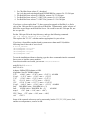
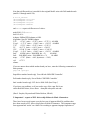
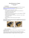
Mark 5/e-VLBI Newsletter
MIT Haystack Observatory
July 2006
Issue #8
The Mark 5/e-VLBI Newsletter is issued from time to time to keep users informed
regarding Mark 5/e-VLBI progress, plans, problems, solutions and workarounds. All
back issues of the Newsletter are available at the Mark 5 web site at
http://www.haystack.edu/tech/vlbi/mark5/newsletter.html. We invite input from anyone
on subjects we should discuss or questions that need answers; please send them to
[email protected]. General information about the Mark 5 and e-VLBI is
available at the Haystack web site at http://www.haystack.edu/.
Contents of this Issue
1. 5th Annual e-VLBI workshop 17-20 Sep 2006 at Haystack Observatory
2. Mark 5B is coming
3. Newly available 750GB disks cross a threshold
4. Software voltmeter for Mark 5 units
5. Important! – reports of ECL driver-chip failures in Mark 4 formatters
6. How to handle a Mark 5 disk module
7. e-VLBI report
1. 5th Annual e-VLBI workshop 17-20 Sep 2006 at Haystack Observatory
The 5th International VLBI Workshop will be held at MIT Haystack Observatory 17-20
Sep 2006. This year we are expanding the workshop to include 2 days of tutorials prior
to the main 2-day workshop itself.
The first two days (Sun-Mon) will feature tutorials on a variety of e-VLBI related
subjects of interest, presented by both Internet2 and Haystack staff. Though the details
are still forming, the topics will include:
1. ISO layer fundamentals
2. TCP fundamentals
3. TCP tuning
4. Mark 5 tuning for e-VLBI
5. Performance - definition, tools, techniques
4. VSI-E protocol fundamentals
6. Optically-switched networks
7. Mark 5B tutorial and demonstration
Due to the interest in Mark 5B, we are planning a special Mark5B tutorial and
demonstration on Monday, 18 Sep. This will be the only opportunity for hands-on
learning about the Mark 5B at Haystack until the planned TOW meeting next spring.
We are soliciting papers on all topics relating to e-VLBI; deadline for abstract submission
has been extended to 15 August 2006. Subjects include, but are not limited to:
• Reports on e-VLBI tests and demonstrations
• Plans for ongoing e-VLBI development
• Status of interaction with network providers and developers
1
•
•
•
•
International networking facilities - now and future
Standards and protocols for e-VLBI data transfer.
Hardware and software interfaces to telescope back-ends and correlators
Related projects
Please feel free to talk or correspond with any members of the program committee about
your paper:
Yasuhiro Koyama, NICT
Jon Romney, NRAO
Arpad Szomoru, JIVE
Tasso Tzioumis, CSIRO
Alan Whitney, Haystack
Registration is at http://www.haystack.edu/geo/vlbi_td/meeting.html; registration
deadline is 21 August.
Hotel reservations at the special workshop rate may be made directly from the workshop
website; the deadline for special pricing for the hotel is 17 August 2006.
Please e-mail Alan Whitney at [email protected] with any question or
comments.
2. Mark 5B is coming!
The Mark 5B system is nearing initial deployment. In this short article we will attempt to
answer some basic questions:
A. What is Mark 5B?
B. What is the status of Mark 5B?
C. Who needs Mark 5B?
D. How can I upgrade my Mark 5A to Mark 5B?
E. How do I interface a Mark 5B to my existing data-acquisition system?
F. Is there any compatibility between Mark 5A and Mark 5B?
G. How will Mark 5B recordings be correlated?
H. How is software support for Mark 5B organized?
I. Where can I get more information about Mark 5B?
J. Where can I get a Mark 5B? How much does it cost?
K. I’ve heard of Mark 5B+. What is that all about?
2
Figure 1: Mark 5B looks identical to Mark 5A
A. What is Mark 5B?
Mark 5B is similar to Mark 5A, except that Mark 5B supports a VSI-H interface (see
http://web.haystack.edu/vsi/index.html). It uses the same chassis and the same disk
modules, but requires a Mark 5B I/O interface PCI board instead of the Mark 5A. The
maximum data rate is still 1024 Mbps.
A major difference is that the Mark 5B has a built-in formatter so that an external
formatter is unnecessary. The Mark 5B directly accepts unformatted sampler data in
VSI-H format; the data are formatted and time-tagged within the Mark 5B.
B. What is the status of Mark 5B?
Mark 5B systems have been used successfully in several real VLBI experiments,
including use with both a modified Mark 4 formatter (so-called ‘VSI Mark 4 formatter’)
and with prototype digital backends (DBE). Mark 5B systems connected to the Haystack
Mark 4 correlator were used to process this data, eliminating the need for Station Units.
Mark 5B I/O boards will soon be distributed to members of the Mark 5 development
consortium, and are currently orderable from Conduant Corp (see below).
C. Who needs Mark 5B?
If you currently have a Mark 5A system, you probably do not need Mark 5B. The only
exception to this rule is that, if your current formatter is limited to less than 1024 Mbps,
using the Mark 5B may allow you to increase your maximum date rate to 1024Mbps.
The prime example is the VLBA, where the VLBA samplers can generate 1024Mbps of
data, but the VLBA formatter is limited to 512Mbps; using the Mark 5B will allow a
VLBA system to increase its data rate to 1024Mbps.
There are three other cases where Mark 5B may be the best choice: 1) New VLBI stations
can avoid the expense of an external formatter with the use of Mark 5B, though a suitable
VSI-H interface must be provided, 2) the new digital-back-ends (DBEs), some of which
have already been demonstrated, support built-in VSI-H outputs that interface directly to
Mark 5B, and 3) if you are currently using a Mark 4 formatter, it may be possible to
upgrade the available aggregate data rate from 1024Mbps to 1792Mbps – see below.
3
D. How can I upgrade my Mark 5A to Mark 5B?
Upgrading a Mark 5A to a Mark 5B requires removing the Mark 5A I/O interface and I/O
panel and installing a Mark 5B interface card. Optionally, a small panel with an array of
8 tri-colored LEDs is installed in a cutout in the lower-right of the front panel. Of course,
a software upgrade is also required.
E. How do I interface a Mark 5B to my existing data-acquisition system?
There are two answers, depending on whether you currently use a Mark 4 formatter or a
VLBA formatter. If you have a Mark 4 formatter, a non-reversible (or at least difficult to
reverse) modification to the Mark 4 formatter is available to create two VSI-H outputs;
for a DAS with 14 BBCs, this increases the maximum recordable data rate from
1024Mbps to 1792Mbps using two Mark 5B recorders in parallel. If you have a VLBA
formatter, the VLBA formatter is discarded and replaced by a Metsahovi VSI-C board
which translates VLBA sampler data to a VSI-H format
(http://kurp.hut.fi/vlbi/instr/boards/).
Haystack Observatory will accept a one-time-only order for kits to upgrade a Mark 4
formatter to VSI-H compatibility; the deadline for participating in this one-time-only
order is 30 September 06 and the cost is ~$2000. A commercial supplier for these
upgrade kits will be available following the Haystack one-time-only build, but likely at a
somewhat higher price. Upgrading a VLBA system for VSI-H compatibility requires a
VSI-C board available from Metsahovi for ~600 Euros.
F. Is there any compatibility between Mark 5A and Mark 5B?
A single compatibility path between the Mark 5A and Mark 5B is available: Augmented
Xilinx code has been designed for the Mark 5A, dubbed ‘Mark 5A+’, to allow Mark 5B
recordings to be played on Mark 5A+ units and create VLBA-format output ‘tracks’
compatible with current Mark 4 and VLBA correlators. No new hardware is required to
upgrade a Mark 5A to a Mark 5A+; a small amount of software work at correlators will
be necessary to support the Mark 5A+ modes. Playback of standard Mark 5A recordings
on a Mark 5A+ unit is unaffected. The capabilities of the Mark 5A+ are detailed in
Mark 5 memo #39 available at http://www.haystack.edu/tech/vlbi/mark5/memo.html.
G. How will Mark 5B recordings be correlated?
Using a Mark 5A+ playback system at a correlator, a Mark 5B recording can be
correlated just like a Mark 5A recording. Alternatively, an interface box has been
designed that allows the Mark 5B to directly connect to a Mark 4 correlator; this
approach has the advantage of completely bypassing the troublesome Mark 4 Station
Units, though a considerable amount of software upgrade work is required to support this
new configuration. The Haystack Mark 4 correlator now supports direct connection of
Mark 5B units to the correlator; the correlators at MPI and USNO will be updated to a
4
similar capability in the near future. The JIVE correlator will support Mark 5A+ in the
short term, but also plans direct connections to Mark 5B units in the future. The VLBA
correlator will support Mark 5A+ on most of its playback units, but there are no current
plans for direct connection of Mark 5B units.
H. How is software support for Mark 5B organized?
The Mark 5B Xilinx firmware can be configured under software control to be either a
Data Input Module (DIM) for use at a station or a Data Output Module (DOM) for use at
a correlator, but cannot be both at the same time. This is unlike the Mark 5A, which
incorporates both the DIM and DOM capability into a single Xilinx configuration.
Furthermore, software support for Mark 5B DIM and DOM are separated as well. The
DOM is controlled by a module named domino (pronounced with emphasis on ‘dom’)
and the DIM is controlled by a software module named dimino (pronounced with the
emphasis on ‘dim’). The dimino program is similar to the ‘Mark5A’ program and will
work with the Field System for data-taking. The domino program, on the other hand, is
specifically crafted for interfacing with a correlator and exercising the SU-emulating
capability of the Mark 5B, and uses a messaging structure for communication; each
correlator will need to customize domino to meet its own specific needs. A version of
domino has already been written to support the Mark 4 correlators at Haystack, MPI and
USNO; modified versions of domino will be needed to support other correlators.
I. Where can I get more information about Mark 5B?
The Haystack Mark 5 website at http://www.haystack.edu/tech/vlbi/mark5/index.html
contains much more information about Mark 5B, including first editions of the Mark 5B
User’s Manual and the Mark 5B Command Set. In addition, the Mark 5 memos series
contains a number of documents relating to the Mark 5B for those interested in digging
into more details.
J. Where can I get a Mark 5B? How much does it cost?
The Mark 5B can be ordered from Conduant Corp (www.conduant.com). A complete
Mark 5B system without disk modules is available for $20,329. Cost for a Mark 5B I/O
interface board to upgrade a Mark 5A to Mark 5B is $2430. VSI-H 80-pin data cables
(2m) are available from Conduant for $304 each. A complete price list is available from
Conduant ([email protected]).
K. I’ve heard of Mark 5B+. What is that all about?
The Mark 5B I/O interface board has been designed to support a recording rate of 2Gbps
(32 bit-streams at 64 Mbps) in anticipation of the availability of an upgraded StreamStor
card from Conduant, dubbed ‘Amazon’. Haystack is currently in the process of
integrating the Amazon board with the Mark 5B I/O board and testing at a recording rate
of 2Gbps; we expect that the ‘Amazon’ system will be ready for field use sometime later
in 2006. The maximum playback rate of Mark 5B with the Amazon board will still be
5
1Gbps, which is consistent with the maximum playback rate accepted by the Mark 4
correlator.
3. Newly available 750GB disks cross a threshold
Seagate recently announced availability of a 750GB disk drive. This is a magic number
for Mark 5, as a Mark 5 loaded with 2 modules of 750GB disks can, for the first time,
record 1Gbps for 24 hours unattended! At the beginning of the development of Mark 5 in
2001, we predicted that such disk capacity would be available in ~2004-5, so we were a
little off, but not too far. These drives are currently available only with a SATA interface
and are relatively expensive, so they probably are not currently economical for most
VLBI users. However, within 6-12 months the $/GB cost of these disks will drop to
more competitive levels as still larger-capacity disks become available.
4. Software voltmeter for Mark 5 units
Nearly a year ago problems were recognized in the power supplies of some Mark 5 units
(see http://www.haystack.edu/tech/vlbi/mark5/docs/power_supply.pdf) and a replacement
supply by PC Power Supply and Cooling was recommended. Since then, we have
observed failure of several of the "good" Antec power supplies after months of successful
operation. The failure mode is a drop in the +5 volts to less than 4.7 volts after the
system has warmed up. This sagging voltage causes some, but not all, disk modules to
appear to have bad drives because some disk drives are more tolerant of the low voltage
than others. If your Mark 5 unit has an Antec power supply, we strongly recommend that
you replace it with the recommended power supply. In the meantime, many
motherboards, including the original Dell and SuperMicro motherboards, support
software monitoring of supply voltages, as explained below. Such monitoring is
recommended until such time as you are able to install the recommended power supply.
Linux provides a "sensors" command that uses voltage sensors on the motherboard to
measure power supply voltages. It is easy to install and configure the 'lm_sensors'
package on a Mark 5 system. Once the 'sensors' command is working, it is easy to
monitor the power supply voltages as power is applied to the disk modules.
Conduant delivered a few systems in late 2005 with sensors already installed, so first
enter ‘/usr/bin/sensors’ at a linux prompt to see if it is already installed. Later in 2005,
Conduant started delivering systems with Intel mother boards; and we have not been able
to get sensors working with these new mother boards. If you are unsure about which
mother board you have, see below. If you get sensors working with the Intel mother
board, please let us know how you did it, so we can share this information with the Mark
5 community.
To install the Red Hat sensors program, first determine which release of Red Hat is
installed on your Mark 5 unit by entering:
cat /etc/redhat-release
Then download the appropriate lm_sensors .i386.rpm file from the Haystack server:
6
1. For "Red Hat Linux release 9", download
ftp://web.haystack.mit.edu/pub/mark5/RPMS/RH9/lm_sensors-2.6.5-5.i386.rpm
2. For Red Hat Linux release 8.0: RH8/lm_sensors-2.6.3-2.i386.rpm
3. For Red Hat Linux release 7.3: RH7.3/lm_sensors-2.6.1-1.i386.rpm
4. For Red Hat Linux release 7.2: RH7.2/lm_sensors-2.5.5-6.i386.rpm
If you have a release earlier than 7.2, then you need to upgrade to Red Hat 9, or find a
copy of the .i386.rpm file for your release of Red Hat. Unfortunately, earlier releases of
these files are no longer on the Red Hat Server. Be careful to use the .i386.rpm file, not
the .src.rpm file.
Put the .i386.rpm file in the /tmp/ directory, and type the following command:
rpm -ivh /tmp/lm_sensors-2.6.5-5.i386.rpm
This replaces the "2.6.5-5" with the numbers appropriate for your release.
If you have a SuperMicro mother board (systems newer than mark5-20) add the
following lines to the end of /etc/rc.local:
# For lm_sensors:
/sbin/modprobe i2c-piix4
/sbin/modprobe i2c-dev
/sbin/modprobe i2c-proc
/sbin/modprobe lm87
To test the installation without re-booting, type the above commands into the command
line as root, to load the sensor modules.
Once these modules are loaded, just execute /usr/bin/sensors:
mark5fx16<6>% sensors
lm87-i2c-0-2e
Adapter: SMBus PIIX4 adapter at 0580
Algorithm: Non-I2C SMBus adapter
2.5V:
+0.00 V (min = +2.36 V, max = +2.63 V) ALARM
Vccp1: +1.43 V (min = +1.36 V, max = +1.51 V)
3.3V:
+3.30 V (min = +3.12 V, max = +3.47 V)
5V:
+5.10 V (min = +4.73 V, max = +5.26 V)
12V:
+12.18 V (min = +11.37 V, max = +12.62 V)
Vccp2: +0.00 V (min = +1.36 V, max = +1.51 V) ALARM
fan1: 5400 RPM (min = 3000 RPM, div = 2)
fan2:
0 RPM (min = 3000 RPM, div = 2)
ALARM
temp1:
+31C (min = +10C, max = +60C)
CPU_Temp: +37C (min = +10C, max = +60C)
vid:
+1.45 V
Some of the reported values may not be trustworthy, but the 3.3V, 5V, 12V power, fan1,
and the two temperatures, seem to be OK.
7
Note that a different driver is needed for the original Mark5 units with Dell motherboards
(mark5-01 through mark5-20):
# For lm_sensors:
/sbin/modprobe i2c-piix4
/sbin/modprobe i2c-dev
/sbin/modprobe i2c-proc
/sbin/modprobe adm9240
and sensors reports a different set of values:
mark5vlb1<3>% sensors
lm81-i2c-0-2c
Adapter: SMBus PIIX4 adapter at 0580
Algorithm: Non-I2C SMBus adapter
2.5V:
+2.76 V (min = +2.22 V, max = +2.72 V) ALARM
Vccp1: +1.75 V (min = +2.40 V, max = +2.93 V) ALARM
3.3V:
+3.35 V (min = +2.93 V, max = +3.59 V)
5V:
+4.97 V (min = +4.45 V, max = +5.44 V)
12V:
+12.00 V (min = +10.68 V, max = +13.06 V)
Vccp2: +1.50 V (min = +2.40 V, max = +2.93 V) ALARM
fan1:
0 RPM (min = 3000 RPM, div = 2)
ALARM
fan2: 2848 RPM (min = 3000 RPM, div = 2)
ALARM
temp:
+37.5C (limit = +60C, hysteresis = +50C)
vid:
+1.75 V
alarms:
If you are unsure about which mother board you have, enter the following command at a
linux prompt:
grep IDE /proc/pci
SuperMicro mother boards reply ’ServerWorks OSB4 IDE Controller’
Dell mother boards reply ‘ServerWorks CSB5 IDE Controller’
Intel mother boards reply ‘PCI device 8086:24d1 (Intel Corp.)’
If you have any problems, or if you need a copy of the .rpm file for an
earlier Red Hat release, let me know. <dsmythe at haystack.mit.edu>
(Dan L. Smythe, Haystack and Walter Brisken, NRAO)
5. Important! – reports of ECL driver-chip failures in Mark 4 formatters
There have been several reports over the last year of apparent Mark 5A problems that
have been traced to ECL driver-chip failures in Mark 4 formatters. The symptoms range
from apparent bad ‘tracks’ on a Mark 5A recording to apparent improper operation of
8
Mark 5A when recording (if the clock line to the Mark 5A has failed). The failed chips
are ECL 100324 driver chips which plug into sockets on the ‘formatter’ board in the
Mark 4 formatter. The ECL 100324 chip is still being manufactured by Fairchild
Semiconductor and is available (in the U.S., at least) for less than $10 each. If you are
seeing any of the symptoms listed, please keep this in mind as a possible failure mode.
6. How to handle a Mark 5 disk module
For the past year or more most of us have been using the Mark 5A recording system.
Though this change from tape has led to a tremendous improvement in reliability, it has
also raised some new issues that must be addressed. In this note, we address the issue of
the handling of the Mark 5 disk modules, which differs from tape in a number of ways.
Please follow the following instructions:
1. Like tape, a disk module cannot withstand a drop onto the floor outside of its
shipping container. The disks are fragile, and the high G-forces created by even a
small drop or careless handling on a hard surface can potentially damage disks.
2. It is recommended that disk handling be done on soft surfaces whenever possible.
Storage shelves should be covered with a soft material such as static-resistant
carpeting.
3. Carefully inspect each disk pack for any mechanical damage when it arrives from
the correlator. Remove the shipping covers and carefully place the module on a
hard, flat surface to confirm that it lies absolutely flat with no rocking. With a
known square jig, also check that the back corners are square. If either of these
two tests fail, loosen and re-tighten modules screws as necessary to assure proper
module alignment.
4. Inspect the connector on the back of the module for damage to the mounting or to
any pins.
5. To insert a module into a Mark 5 chassis:
a. Verify that the keyswitch is in the “Off” position (fully counter-clockwise).
b. Before insertion, fully depress the front-panel locking lever.
c. Carefully slide the module into the chassis until it stops (about 1cm short of full
insertion). Do not force and do not lift the module; if there is a need to exert
any force, this is an indication of module misalignment. Immediately stop,
remove the disk pack, and re-check the module alignment before proceeding
(Step 3 above).
d. While placing gentle pressure on the upper left corner of the module with one
hand, carefully lift the locking lever to the full upright and locked position. Do
not force. Forcing can damage the connectors of both the Mark 5 unit and the
module. If any undue force seems to be necessary, immediately remove the
module and re-check alignment.
e. Turn the keyswitch to the “On” position (90 deg clockwise) to apply power and
complete the mounting operation.
6. To remove a module:
a. Turn the keyswitch to the “Off” position and wait several seconds while the
disks spin down.
9
b. Fully depress the front-panel locking lever. The module will back out about
1cm.
c. Slide the module out and remove it.
If a module is damaged beyond easy repair, ship the disk pack back to a correlator where
a qualified technician will repair the module and put it back into service. As a reminder,
a mechanically damaged disk module may have hard-disk damage that is not detected
until further testing is completed.
7. e-VLBI report
The VLBI station in NyAlesund has recently been connected to the Internet at ~100Mbps.
Through the cooperation of many people in Europe and the U.S., regular geodetic VLBI
data taken at NyAlesund is being increasingly transferred to Haystack via e-VLBI, with a
goal to transmit all data via e-VLBI within a few months. Within the last 2 weeks, more
than 5 TB of data have been transferred from NyAlesund to Haystack. With the
expectation that MPI will soon be network-connected at 1Gbps, data that are targeted to
be correlated at MPI will be transferred there directly.
All geodetic VLBI data taken in Japan, amounting to ~5TB/month, are now being
transferred to Haystack via e-VLBI. Japan poses a special case since the data are
recorded on a K5 system; the data are transferred to Haystack in K5 format, converted to
Mark 5A format, then written to Mark 5A disks and shipped to the target correlator.
We are currently testing VSI-E as a transfer protocol and expect to transition all e-VLBI
transfers to VSI-E over the next few months. VSI-E provides many advantages,
including natural support of heterogeneous data platforms, which will greatly ease
international e-VLBI data transfers.
Development efforts continue on e-VLBI with support both from NASA and NSF,
though operational support for geodetic e-VLBI is not currently available.
10