1
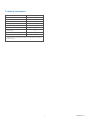
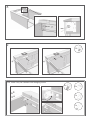
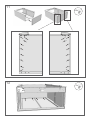
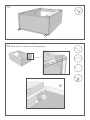
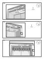
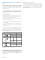
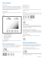
Installation and operation manual
Drying cabinet TS 62
Thank you for choosing this drying cabinet TS 62 from PODAB.
We hope that it will be of great use for you and ask you kindly to
read the instructions carefully.
IMPORTANT!
FOR YOUR SAFETY, the information in this manual must be followed to prevent property damage and personal injury.
NOTE: The paragraphs marked “WARNING” and “CAUTION” appearing in this manual are not meant to cover all possible
conditions and situations that may occur. It is very important that water and electricity are handled with great care and
respect, by both installation technicians and end users.
©PODAB 2011
2
Contents
Safety regulations
4
5
Important safety instructions
Specification 6
6
7
Dimensions
Technical information
Assembly instructions
8
Installation of the cabinet
20
20
21
21
22
22
Step 1: Put the cabinet in place
Step 2: Fasten the cabinet to the wall Step 3: Connect the cabinet to the ventilation channel
Step 4: Connect the drying cabinet to the main switch
Step 5: Control that the heating relay is working
Turn the hanging frame 23
Requirements for ventilation 25
25
25
25
26
Ventilation channel – choice of material
Requirements for incoming air
Ventilation channel – design
Evacuated amount of air and pressure fall
User manual
27
27
27
Manual programme mode
Automatic programme mode
Maintenance
29
Notes
30
3
©PODAB 2011
Safety regulations
Throughout this manual you will find text warnings in text boxes: “WARNING” and “CAUTION”. In these boxes you’ll find the
safety measurements you’ll have to take; end user, service staff
or installation staff.
CAUTION
Indicates hazardous situation that, if not avoided, could cause
minor personal injury or property damage.
WARNING
Indicates hazardous situation that, if not avoided, could cause
severe personal injury.
You will also find precautions marked: IMPORTANT and NOTE.
These are followed by information of what should be considered.
IMPORTANT: to inform the reader of special steps that must
be taken in order to prevent injuries on the cabinet.
NOTE: to inform what is important to know, but it cannot
cause personal injuries or injury on the cabinet.
©PODAB 2011
4
Important safety instructions
WARNING
To minimize the risk of fire, electrical shock, personal injuries
or death when the cabinet is in use the following precautions
must be followed:
1. Read the instruction before using the drying cabinet.
2. Follow the instructions in step 4 for proper grounding.
3. Never dry textiles that have been washed, dipped or exposed to fire dangerous substances or fluids.
4. Never add fire dangerous or explosives substances in the
cabinet.
5. The cabinet is not a toy. Look after the children who are
around the cabinet.
6. Never connect the cabinet with an extension cable.
7. Only use the cabinet for what it is designed for: drying
clothes.
8. Always turn off the main switch before performing any service on the cabinet. Only authorized service technicians
should perform service.
9. Always follow the installation manual. The electrical connections must be done by authorized personnel.
10. Keep after the cabinet. If it is exposed for violence there
is a risk that certain security functions will stop working.
Please contact your nearest service partner if you are unsure of the cabinet’s status.
11. If the electrical cable is damaged, it must immediately be
changed by a person with electrical authorization.
12. The doors shall always be shut when the cabinet is in use.
Don’t try to manipulate the lock of the doors. It can lead
to personal injuries. If the cabinet doesn’t stop when the
doors are opened during the drying phase, call for service.
The cabinet shall not be used if the drying program is active when the doors are open!
13. Look after the area around the evacuating pipe so it is
clean from dust and dirt.
14. To get the best drying result, follow the garments washing
& drying advice.
15. Never use the cabinet if any panel is broken or removed.
16. Never use the cabinet if any parts are broken or if the inside
is broken.
17. Never try to manipulate or connect past any safety functions.
18. If the cabinet isn’t assembled after the manufacturer’s instructions, there is a risk that the cabinet can cause personal injuries or injuries on property.
5
©PODAB 2011
Specification
1870
200
Dimensions
1200
640
469
242
A
1453
B
1855
A = Electrical connection
B= Exhaust
©PODAB 2011
6
Technical information
Loading capacity, kg (lb)
up to 8 (17,6)
Drying capacity, g/min (oz/min)*
91 (3,2)
Hanging length, m (ft)
16 (52,5)
Drying time, min*
Evacuated air, max, m³/h (ft³/h)
35
340 (12007)
Exhaust ø, mm (in)
125 (4,92)
Heating effect, kW
6,0
Total effect, kW
6,3
Energy consumption, kWh/kg (kWh/lb)*
Part No
0,55 (0,48)
131025
*Drying of 6 kg (13,2 lb) cotton (dry weight), washed and high-spinned to 53%
residual moisture. The cabinet works another 15 minutes with cool-down after
the textiles are dry.
7
©PODAB 2011
Assembly instructions
Tools
You need the following tools to easily install the drying cabinet:
(If the cabinet is already assembled please go to page 20)
• Cordless screwdriver
• Wrench
• Hex key 3 and 5 mm
• Level
• Torx screwdriver bit no. 25
1
4x
2
4x
©PODAB 2011
8
3
4
3x
5
4x
9
©PODAB 2011
6
7x
7
10x
Note!
Only for cabinets with hanging frame.
©PODAB 2011
10
8
9
2x
10 Note! Only for cabinets with hanging frame
3x
4x
1x
MAX
1x
11
©PODAB 2011
11
24x
12
©PODAB 2011
4x
12
13
4x
14 Note! Only for cabinets with hanging frame
1x
1x
1x
1x
13
©PODAB 2011
15
4x
16
17
©PODAB 2011
14
18
1x
19
1x
20
8x
15
©PODAB 2011
21 Connect the cables
Keypad
The side
with hole
pattern to
the left.
LCD
22
Lights
Door switch
23
4x
©PODAB 2011
16
24
2x
25 Note! Only for cabinets with hanging frame
A
B
C
D
17
©PODAB 2011
26 Note! Only for cabinets with hanging frame
8x
A
A
B
B
A
B
27 Note! Only for cabinets with single rack bar
28 Note! Only for cabinets with single rack bar
4x
©PODAB 2011
18
29 Note! Only for cabinets with single rack bar
4x
30
19
©PODAB 2011
Installation of the cabinet
Step 1: Put the cabinet in place
3. Disconnect the cables (connected to the LCD and maneuver
panel) from the mother board. Loosen the bulb’s connection
plinth marked “Light”.
4. From the inside of the cabinet, loosen the protection plate (8
screws).
Place the cabinet with enough space in front of the cabinet and
on the sides to be able to open the doors.
The feet of the cabinet can be adjusted from the inside with
the help of a Hex key. The feet must stand free on the floor and
have an even weight distribution. Use a leveler and control that
the cabinet is leveled; horizontally and vertically.
NOTE: We recommend that the cabinet is installed on a firm
and leveled floor.
Please observe that the front panel (on the top) must have at
least 175 mm free space above, in order to take off the top to
perform service.
Narrow spaces
If the cabinet must be transported through narrow spaces, we
recommend that you take off the doors first. It will simplify the
handling and reduces the risk for damages on the doors.
5. Loosen both service hatches which cover the fans. 1 screw
on each service hatch.
Demounting of the top
To simplify the transport of the cabinet, the top can be demounted, see the instructions below.
1. Loosen the two screws which hold the front panel of the
top.
6. Lift the top off.
CAUTION
There must be two persons to lift the top in a safe way. Don’t
try to do it on your own, the weight is 30 kg!
2. Push the panel upwards.
©PODAB 2011
20
Step 2: Fasten the cabinet to the wall
Step 3: Connect the cabinet to the ventilation channel
For further instructions, se page 25: Requirements for ventilation.
Use the stoppers, screws and washers to secure the cabinet
through the back plates. Fastening holes are pre-drilled in the
back plates.
• Do not use ventilation channels made of plastic or foil.
• Place the cabinet so that the ventilation channel is as short
as possible.
• Make sure that the ventilation channel is cleaned when a
new cabinet is installed.
• Use a 125 mm rigid or flexible metal duct to the evacuation
connection.
• If you use rigid ducts, it is important that the male connector of the ventilation tube on each section follows the air
direction.
• The construction shall be as straight as possible.
• Always isolate ducts that go through non-isolated areas.
The condensation makes dust and dirt get stuck in the
channel.
NOTE: If the cabinet is not connected according to these
recommendations, the warranty is no longer valid.
NOTE: Please control that the cabinet is leveled and cannot
be tilted.
21
©PODAB 2011
Step 4: Connect the drying cabinet to the
main switch
Step 5: Control that the heating relay is
working
To prevent that fire and electric shock appear, the cabinet MUST
be connected according to the color codes on the cables. Only
an authorized electrician is allowed to install the electrical connection. The cabinet is prepared for one of the following electrical connections depending on specification:
Shut the doors and start the cabinet, after about 3 seconds you
can hear when the heat relays hit. Wait a couple of minutes and
control that the outgoing air channel becomes warm.
If the outgoing air channel does not get warm, go back to step 4
and control that the electrical connection is installed correctly.
• 400 V, 3-N, 50 Hz (standard)
• 208-240 V, 3~N, 60 Hz
• 220 V, 3~N, 50 Hz
WARNING
It is always the buyer that has the responsibility to check that
an authorized electrician makes the electrical connections of
the cabinet.
WARNING
To prevent personal injuries, the cabinet shall always be connected permanently through an all pole main switch. Always
ground the cabinet.
Also check that the connecting cable has a strain relief bushing. If not, there is a risk that the cabinet will be live.
©PODAB 2011
22
Turn the hanging frame
The hanging frame can be turned. Follow the steps below.
Support plate
1. Loosen the upper Hex Key bolt, which holds the upper
hanging level.
5. Unconnect the two cables which go from the keypad and
LCD to the main control board.
6. Lift up the plate and remove the cables. Connect the cables to the board again.
7. Before the support-plate is assembled on the other side
of the cabinet; loosen the five torx screws on the left hand
side.
8. Put the support-plate on the side to which the hanging
frame will be moved.
9. Re-assemble the torx screws. Thereafter, fasten the bolts,
upper stearing tap and the stop plate.
10. Put the front panel back on again.
11. Loosen and move also the lower tap to the opposite side.
12. To get the arms on the frame on the same level, each hanging level must be turned “upside down”. Loosen the upper
hanging level from the frame.
2. Lift up the hanging frame and hook it off the tap below.
Put aside.
3. Loosen and push the panel on the top.
4. Loosen the three bolts, the upper stearing tap and nut
and the five torx screws which hold the plate and which
support the stop plate. The drawings below shows where
these parts are.
Stop plate
Stearing tap
23
©PODAB 2011
13. Rotate the hanging level 180° and fasten it again. Leave
the upper bolt on the pole, unmounted.
14. Repeat the same moment with the three remaining hanging levels. Fasten both bolts.
15. Put the hanging frame back in and put the pole on the upper tap. Lower the pole so that it fits to the lower stearing
tap.
16. Fasten the Hex Key bolt on the upper hanging level.
17. Control that the frame can be turned and that the stop
function works properly also in the outer positions.
©PODAB 2011
24
Requirements for ventilation
Material, the design and the length of the channel have a large
impact on the air flow. In order to get the best possible performance, the pressure fall shall be as low as possible.
WARNING
A drying cabinet produces inflammable dust. To minimize the
risk for fire, the evacuation of the cabinet must be connected
to a ventilation channel that evacuates the air.
When the air is transported through the channel, it is exposed
to different kind of resistance. Factors that give a low pressure
fall:
Never let the evacuated air into a room or a surrounding where
there is a risk for ignition.
•
•
•
•
•
Do not use ventilation channels in plastic or fire dangerous
material.
Smooth inner walls on the pipe
Large diameter on the pipe
Short length on the pipe
Few curves
Few angels (90 degrees)
Ventilation channel – choice of material
Ventilation channel, ducts, connections etc are not included.
The ventilation channels shall be at least 125 mm in diameter
and should not have channels or similar on the inside.
We recommend that the ventilation system is built with rigid
metal ducts for best result. Flexible evacuating ducts for drying
cabinets can also be used.
NOTE: Never use flexible ducts through walls or other covered areas.
NOTE: Do not screw or nit the ventilation channel, so that
the screws will come through the inside of the pipe. This
construction will gather dust and impaire the cabinet’s performance.
The channel shall always be separated from the other ventiltion
in the house.
Requirements for incoming air
In order to make the cabinet work properly, it is very important
that there is enough incoming air in the room. If he cabinet is
installed according to this manual the air flow from the exhaust
will be about 230 m³/h. Incoming air must be at least equal to
the outgoing flow. We recomend the incoming air flow to the
room to be greater than the evacuated amount.
If the cabinet is placed in a room where the incoming air is not
enough, we recommend that you install an air exchanger.
Ventilation channel – design
IMPORTANT: Always make the channels as short as possible.
NOTE: If a drying cabinet is installed in an old ventilation
channel, please clean the channel properly.
In order to make the cabinet work properly, the incoming airflow must be enough. The amount of evacuated air per hour
is depending on how high the pressure fall in the ventilation
channel is.
25
©PODAB 2011
Evacuated amount of air and pressure
fall
Decrease the outgoing air flow
The cabinets function and automatic programmes are optimized for the recommended air flow of 230 m³/h. If the design of
the ventilation is made so that evacuated air flow exceeds 230
m³/h, the evacuation can be throttled with help of a damper.
Contact a ventilation expert in order to find a proper solution
for your ventilation.
In order to get the cabinet to work properly, the ventilation
channel shall be designed to get an out coming air flow from
the cabinet of about 230 m³/h. When the cabinet is installed to
an existing channel system, the cabinet can be calibrated to
optimize the air flow.
In order to gain this air flow, the pressure fall must not exceed
70 Pa. By an airflow of 230 m³/h and a diameter of the pipe
of 125 mm, this corresponds to a straight, smooth ventilation
channel of 23 m.
Pressure fall estimation
The counter pressure in the ventilation channel can be measured with a pressure meter. The measuring point shall be
placed by the cabinets evacuating outlet.
In order to estimate the pressure fall without meter equipment
we recommend the following:
• Identify the ventilation channel’s incoming components in the
air flow direction.
• Check the part pressure fall for each component in the table.
• Calculate the total amount of pressure fall by adding each
parts pressure fall.
The table shows the most common components in a ventilation
system. The information shall be considered as approximate
data. For more information, contact the manufacturer of the
parts of the system. Please note that the data in the table is for
an air flow of 230 m³/h.
Component
Pressure fall
Circular channel
Ø
Ø
Pipe bends 90º
ØØ
r
ø, mm
Pa/m
125
3,1
160
1,0
ø, mm
r, mm
Pa/bend
125
125
6,5
160
160
2,5
Ø
r
Ø
r
Reduction
Transition, mm
Pa/reduction
125 till 160
3,5
160 till 125
5,5
Example: 10 m long 125 mm channel with 3 pipe curves which gives an estimated
pressure fall of (10 x 3,1) + (3 x 6,5) = 50,5 Pa.
NOTE: If the highest allowed level of air pressure is exceeded an external fan could be needed. Otherwise the drying
result is effected negatively. TS 62 is prepared for an external fan. Contact your local dealer or PODAB for more
information.
©PODAB 2011
26
User manual
Fill the cabinet
There are three levels:
Minimum (MIN) = 40ºC
Medium (MED) = 60ºC
Maximum (MAX) = 80ºC
To get the best drying result: try to dry the same type of material with the same thickness at the same time. Distribute the
clothing evenly in the cabinet. Never fill the cabinet with more
than 8 kg laundry (dry weight). The most heat sensitive garment
decides how high temperature that can be chosen.
The degrees stated above, show the maximum temperature of
the warm air stream.
Close the doors
Set time
The drying cabinet won’t start until the doors are completely
closed.
Increase or reduce the drying time with the arrow buttons 6 and
7. The drying time can be increased to maximum 3 h. Lower
temperature requires longer drying time.
Keypad
1
2
Start
Push button 5 to start the cabinet.
8
Pause programme
To pause a working programme, open the doors. The drying
time is paused. Close the doors and push start button to continue drying. If the doors are left open longer than 10 minutes,
the programme is interrupted.
Change temperature or time during drying
3
4
5
6
Temperature and time can be adjusted during the drying process and the programme is in the heating phase. When the
cabinet switches to cool down, neither time nor temperature
can be changed.
7
1. Manual programme mode
2. Automatic programme mode*
3. Reduce the temperature
4. Increase the temperature
5. Start/stop the programme
6. Reduce the time
7. Increase the time*
8. LCD-display
*Will also change programme when you’re in the automatic programme mode.
Interrupt a programme
To interrupt a working programme, push the START/STOP
button.
Automatic programme mode
The drying cabinet is equipped with the function HTS –
Humidity Tracking System. This function is activated in the automatic programme mode. The drying time adjusts to the laundry in the cabinet and is controlled by a humidity sensor.
Manual programme mode
In order to set the time and temperature, push key no 1. LCD
shows the settings for manual programmes. The cabinet is preset
on average temperature 60ºC and 45 minutes drying time.
To choose automatic programme mode
Choose automatic programme mode by pushing button 2.
Set the temperature
Increase or reduce the temperature with the arrow buttons 3 and 4.
The cabinet has two automatic programmes; wardrobe dry and
iron dry. By choosing either of those programmes, the drying
time is adjusted automatically.
27
©PODAB 2011
Programme wardrobe dry
When automatic mode is activated, the programme “wardrobe
dry” is set as first choice. Wardrobe dry means that the clothes
are completely dry when the programme is finished.
Programme iron dry
To change automatic programme, push button no 2 once more.
Programme “iron dry” dries the clothes until about 15% residual moisture is left in the textiles. Use this programme when you
have clothes that shall be ironed or mangled directly after the
drying.
Automatic programmes; temperature
Automatic programme uses the maximum temperature of 80ºC.
Use manual programme mode for clothes that shall be dried in
lower temperatures.
Start programme
Push button 5 to start the cabinet.
Pause programme
To pause a working programme, open the doors. The drying
time is paused. The cabinet will start again when the doors are
closed and the start button is pushed. If the doors are left open
longer than 10 minutes, the programme is interrupted.
Interrupt a programme
To interrupt a working programme, push the START/STOP
button.
Cool down
All programmes, both manual and automatic ones, have a cool
down phase of 15 minutes. This time is in the chosen time
when you chose the manual programmes. During cool down
the clothes are reconditioned and the drying cabinet is cooled
downed.
CAUTION
If a program is interrupted before the cool down has finished,
the ceiling of the cabinet could be very hot.
©PODAB 2011
28
Maintenance
Take good care of the cabinet
Only use a damp cloth with a mild detergent when cleaning the
cabinet. Never use solvent to clean the display.
Ventilation system
Loosen the ventilation pipe on the cabinet every year and clean
if necessary around the evacuating channel.
IMPORTANT: Always switch off the electricity before starting to work with the cabinet.
Inspect with set intervals the complete ventilation channel;
don’t forget the outer wall. There can easily be leafs and other
rubbish that chokes.
We recommend that you once a year, take down the service
doors and vacuum clean around the fans and elements.
Keep your cabinet efficient and economical
• The ventilation channels shall be as short as possible.
• If possible, dry the same type of textiles at the same time.
• Do not dry with maximum temperature if you do not need to.
29
©PODAB 2011
Notes
©PODAB 2011
30
31
©PODAB 2011
SERVICE/SUPPORT
Phone +46 31-752 01 00
Fax +46 31-752 01 50
E-mail [email protected]
www.podab.com
AB PODAB, Ekonomivägen 9, 436 33 Askim, SWEDEN
Tel +46 (0)31-752 01 00, Fax +46 (0) 31-752 01 50 E-mail: [email protected], www.podab.com
©PODAB 2011-01-21