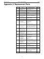
1
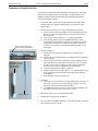
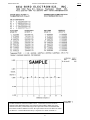
SBE 35 Deep Ocean Standards Thermometer User’s Manual Sea-Bird Electronics, Inc. 13431 NE 20th Street Bellevue, Washington 98005 USA Telephone: +1 425-643-9866 Manual Version #012, 04/25/13 Fax: +1 425-643-9954 Firmware Version 2.0a and later [email protected] Seasave V7 Version 7.22.5 and later www.seabird.com SBE Data Processing Version 7.22.5 and later Limited Liability Statement Extreme care should be exercised when using or servicing this equipment. It should be used or serviced only by personnel with knowledge of and training in the use and maintenance of oceanographic electronic equipment. SEA-BIRD ELECTRONICS, INC. disclaims all product liability risks arising from the use or servicing of this system. SEA-BIRD ELECTRONICS, INC. has no way of controlling the use of this equipment or of choosing the personnel to operate it, and therefore cannot take steps to comply with laws pertaining to product liability, including laws which impose a duty to warn the user of any dangers involved in operating this equipment. Therefore, acceptance of this system by the customer shall be conclusively deemed to include a covenant by the customer to defend, indemnify, and hold SEA-BIRD ELECTRONICS, INC. harmless from all product liability claims arising from the use or servicing of this system. 2 Manual revision 012 Declaration of Conformity Declaration of Conformity 3 SBE 35 Manual revision 012 Table of Contents SBE 35 Table of Contents Limited Liability Statement ............................................................................2 Declaration of Conformity ..............................................................................3 Table of Contents .............................................................................................4 Section 1: Introduction ....................................................................................6 About this Manual .............................................................................................6 Unpacking SBE 35.............................................................................................7 Section 2: Description of SBE 35 ....................................................................8 System Description ............................................................................................8 SBE 35 Specifications........................................................................................9 Interface Box Specifications ..............................................................................9 Interface Box Connectors, Switches, and LEDs ................................................9 Dimensions and End Cap Connector ...............................................................10 Cables and Wiring ...........................................................................................11 Section 3: Preparing for Deployment ...........................................................13 Software Installation ........................................................................................13 Power and Communications Test ....................................................................14 Test Setup .................................................................................................14 Test ...........................................................................................................15 Command Descriptions ....................................................................................19 Data Formats ....................................................................................................23 Section 4: Deploying and Operating SBE 35 ...............................................25 Operation with CTD, Deck Unit, and SBE 32 Carousel Water Sampler .........25 Deployment with SBE 9plus CTD, SBE 11plus Deck Unit, and SBE 32 Carousel Water Sampler ..............................................................26 Deployment with SBE 19, 19plus, 19plus V2, 25, or 25plu CTD; SBE 33 Deck Unit; and SBE 32 Carousel Water Sampler .......................27 Recovery ...................................................................................................28 Uploading Data from SBE 35 ...................................................................29 Comparing SBE 35 Data to CTD Data .....................................................31 Operation in Fixed-Point Cells ........................................................................32 Section 5: Routine Maintenance and Calibration .......................................33 Corrosion Precautions ......................................................................................33 Connector Mating and Maintenance ................................................................33 Cleaning Interface Box ....................................................................................34 Calibration .......................................................................................................34 Glossary ..........................................................................................................40 Safety and Electrical Symbols .........................................................................41 4 Manual revision 012 Table of Contents SBE 35 Appendix I: Functional Description .............................................................42 Measurement Cycle .........................................................................................42 Real-Time Clock ..............................................................................................43 Memory............................................................................................................43 Appendix II: Electronics Disassembly/Reassembly ....................................44 Appendix III: Command Summary .............................................................45 Appendix IV: References ..............................................................................46 Appendix V: Replacement Parts ..................................................................47 Appendix VI: Manual Revision History ......................................................48 Index................................................................................................................49 5 Manual revision 012 Section 1: Introduction SBE 35 Section 1: Introduction This section includes contact information and photos of a standard SBE 35 shipment. About this Manual This manual is to be used with the SBE 35 Deep Ocean Standards Thermometer. It is organized to guide the user from installation through operation and data collection. We’ve included detailed specifications, command descriptions, maintenance and calibration information, and helpful notes throughout the manual. Sea-Bird welcomes suggestions for new features and enhancements of our products and/or documentation. Please contact us with any comments or suggestions ([email protected] or 425-643-9866). Our business hours are Monday through Friday, 0800 to 1700 Pacific Standard Time (1600 to 0100 Universal Time) in winter and 0800 to 1700 Pacific Daylight Time (1500 to 0000 Universal Time) the rest of the year. 6 Manual revision 012 Section 1: Introduction SBE 35 Unpacking SBE 35 Shown below is a typical SBE 35 shipment. SBE 35 SBE 35 to Interface Box cable Interface Box Interface Box to computer cable Software, and Electronic Copies of Software Manuals on CD-ROM 7 AC power cord for Interface Box Manual revision 012 Section 2: Description of SBE 35 SBE 35 Section 2: Description of SBE 35 This section describes the functions and features of the SBE 35, including specifications, dimensions, and connectors. System Description Note: Each sample consists of NCycles= measurements (1 – 127), with the average of the measurements stored and/or transmitted as applicable. The SBE 35 is an accurate, ocean-range temperature sensor that can be standardized against Triple Point of Water and Gallium Melt Point cells as if it were a Standards-grade Platinum Resistance Thermometer (SPRT), but is also capable of measuring temperature in the ocean to depths of 6800 meters (22,300 ft). The SBE 35 communicates via a standard RS-232 interface at 300 baud, 8 data bits, no parity. The SBE 35 is supplied with an Interface Box for setup and lab use. The Interface Box provides continuous, isolated power to the SBE 35 and buffers the serial communication lines to minimize noise input to the SBE 35 from external sources. When used with the Interface Box, user-selectable operating modes are: • Sample continuously and output real-time data (data is not stored in EEPROM), or • Take a single sample, store data in EEPROM, and output real-time data. The SBE 35 can also be used with the SBE 32 Carousel Water Sampler and one of the following CTD systems: • Real-Time Operation - SBE 9plus CTD with SBE 11plus Deck Unit, or - SBE 19, 19plus, 19plus V2, 25, or 25plus CTD with SBE 33 Deck Unit • Autonomous Operation (details not documented in this manual) - SBE 9plus CTD with SBE 17plus V2 Searam, or - SBE 19, 19plus, 19plus V2, 25, or 25plus CTD with Auto Fire Module (AFM) Notes: • Help files provide detailed information on the software. • Separate software manuals on CDROM contain detailed information on the setup and use of Seasave V7 and SBE Data Processing. • Sea-Bird supplies the current version of our software when you purchase an instrument. As software revisions occur, we post the revised software on our FTP site. See our website (www.seabird.com) for the latest software version number, a description of the software changes, and instructions for downloading the : software from the FTP site. The SBE 35 makes a temperature measurement each time a bottle fire confirmation is received, and stores the value in EEPROM. Each stored value contains the time and bottle position in addition to the temperature data, allowing comparison of the SBE 35 record with CTD and water bottle data. Using one SBE 35 eliminates the need for reversing thermometers, and provides higher accuracy temperature readings at lower cost. Calibration coefficients stored in EEPROM allow the SBE 35 to transmit data in engineering units. When configured in a real-time system, the SBE 35 can use the system modem channel for two-way communications; it is not necessary to change cable connections to communicate with and retrieve data from the SBE 35. Commands can be sent to the SBE 35 to provide status display, data acquisition setup, data retrieval, and diagnostic tests. The SBE 35 is supplied with a powerful Windows software package, Seasoft V2, which includes: • Seaterm and SeatermV2 – terminal programs for easy communication and data retrieval. • Seasave V7 – real-time data acquisition and display. • SBE Data Processing – program for calculation and plotting of CTD parameters and derived variables. 8 Manual revision 012 Section 2: Description of SBE 35 SBE 35 SBE 35 Specifications Measurement Range Initial Accuracy Typical Stability (per year) Resolution Sensor Calibration Data Storage Real-Time Clock External Power Current Materials Weight -5 to +35 °C 0.001 °C 0.001 °C 0.000025 °C -1.5 to + 32.5 °C Up to 179 samples (each an average of NCycles= measurements [1 - 127]) Watch-crystal type 9-16 VDC On application of power (approximately 1 minute): 140 – 160 mA Operating: 60 – 70 mA Aluminum pressure case rated at 6,800 meters (22,300 feet) In water: 0.5 kg (1.1 lbs) In air: 0.9 kg (2 lbs) Interface Box Specifications 100-240 VAC / 47-63Hz / 0.30A The Interface Box should always be used with a threeterminal outlet that includes a protective earth. 3AG, 250VAC Slow-Blow, 0.5 Amp 178 x 127 x 57 mm (7 x 5 x 2.25 inch) 1.1 kg (2.5 lbs) Interface Box operates properly under following conditions: • Indoor use • Altitude up to 2000 meters • Temperature from 5 °C to 40 °C • Maximum relative humidity 80% • Mains supply voltage ±10% Power Requirement Fuse Dimensions Weight Installation Environment Interface Box Connectors, Switches, and LEDs • Connections: RS-232 - connects to computer SBE 35 - connects to SBE 35 AC Input - connects to 100-240 VAC power supply • Power switch and LED - switch turns power to Interface Box on/off. Red PWR LED turns on to indicate power is on. • LEDs - indicate if the Interface Box is communicating with other parts of the system: Yellow TX LED - flashes when message is received from SBE 35 Green RX LED - flashes when message is transmitted to SBE 35 Interface Box (front) Interface Box (back) 9 Manual revision 012 Section 2: Description of SBE 35 Dimensions and End Cap Connector Note: Sensor guard not shown. Ensure guard is installed when deploying at sea. 10 SBE 35 Manual revision 012 Section 2: Description of SBE 35 Cables and Wiring 6-pin to MS cable – SBE 35 to Power Supply / Interface Box PN 171887 DB9 to DB9 cable – Power Supply / Interface Box connector to computer 11 SBE 35 Manual revision 012 Section 2: Description of SBE 35 6-pin to 6-pin cable – SBE 35 to SBE 32, when used with SBE 33 Deck Unit Y- cable – SBE 35 to SBE 32 and 9plus, or SBE 35 to SBE 32 and 17plus V2, or SBE 35 to SBE 32 and AFM 12 SBE 35 Manual revision 012 Section 3: Preparing for Deployment SBE 35 Section 3: Preparing for Deployment This section describes software installation, testing and setting up the SBE 35, commands, and data formats. Software Installation Seasoft V2 was designed to work with a PC running Windows XP service pack 2 or later, Windows Vista, or Windows 7. If not already installed, install Sea-Bird software programs on your computer using the supplied software CD: Notes: • It is possible to use the SBE 35 without Seaterm by sending direct commands from a dumb terminal or terminal emulator, such as Windows HyperTerminal. • Help files provide detailed information on the software. • Separate software manuals on CDROM contain detailed information on the setup and use of the software. • Sea-Bird supplies the current version of our software when you purchase an instrument. As software revisions occur, we post the revised software on our FTP site. See our website (www.seabird.com) for the latest software version number, a description of the software changes, and instructions for downloading the software from the FTP site. 1. Insert the CD in your CD drive. 2. Install software: Double click on SeasoftV2.exe. Follow the dialog box directions to install the software. The installation program allows you to install the desired components. Install all the components, or just install Seaterm (terminal program), SeatermV2 (terminal program for use when directly communicating with an SBE 19plus V2 or 25plus), Seasave V7 (real-time data acquisition), and SBE Data Processing (data processing). The default location for the software is c:\Program Files\Sea-Bird. Within that folder is a sub-directory for each program. 13 Manual revision 012 Section 3: Preparing for Deployment SBE 35 Power and Communications Test Test Setup Locking sleeve Dummy plug Test power and communications by communicating with the SBE 35 through the Interface Box: 1. By hand, unscrew the locking sleeve from the SBE 35’s bulkhead connector. If you must use a wrench or pliers, be careful not to loosen the bulkhead connector instead of the locking sleeve. 2. Remove the dummy plug from the SBE 35’s bulkhead connector by pulling the plug firmly away from the connector. 3. Standard Connector - Install the supplied I/O cable on the SBE 35, aligning the raised bump on the side of the plug/cable connector with the large pin (pin 1 - ground) on the SBE 35. OR MCBH Connector – Install the supplied I/O cable on the SBE 35, aligning the pins. 4. Connect the I/O cable to SBE 35 on the Interface Box. 5. Connect RS-232 on the Interface Box to your computer’s serial port using the supplied DB 9P / DB 9S cable. 6. Connect the Interface Box to a standard, 3-prong, grounded AC outlet, using the supplied UL/IEC-approved power cord (AC voltage between 100-240 VAC). Turn on power to the Interface Box. 14 Manual revision 012 Section 3: Preparing for Deployment SBE 35 Test Note: See Seaterm’s help files. Proceed as follows: 1. Double click on SeaTerm.exe. If this is the first time the program is used, the setup dialog box may appear: SBE35 Select the instrument type (SBE 35) and the computer COM port for communication with the SBE 35. Click OK. 2. The main screen looks like this: Menus Toolbar Command/Data Echo Area Status bar Instrument Note: There is at least one way, and as many as three ways, to enter a command: • Manually type a command in Command/Data Echo Area • Use a menu to automatically generate a command • Use a Toolbar button to automatically generate a command Note: Once the system is configured and connected (Steps 3 and 4 below), to update the Status bar: • on the Toolbar, click Status; or • from the Utilities menu, select Instrument Status. Seaterm sends the status command, which displays in the Command/Data Echo Area, and updates the Status bar. Computer COM port Instrument EPROM version • • • • Upload parameter Capture to file status – grayed out if not capturing Baud rate, data bits, stop bits, and parity Menus – Contains tasks and frequently executed instrument commands. Toolbar – Contains buttons for frequently executed tasks and instrument commands. All tasks and commands accessed through the Toolbar are also available in the Menus. To display or hide the Toolbar, select View Toolbar in the View menu. Grayed out Toolbar buttons are not applicable. Command/Data Echo Area – Echoes a command executed using a Menu or Toolbar button, as well as the instrument’s response. Additionally, a command can be manually typed in this area, from the available commands for the instrument. Note that the instrument must be awake for it to respond to a command (use Connect on the Toolbar to wake up the instrument when using it with the Interface Box). Status bar – Provides status information. To display or hide the Status bar, select View Status bar in the View menu. 15 Manual revision 012 Section 3: Preparing for Deployment SBE 35 Following are the Toolbar buttons applicable to the SBE 35: Toolbar Button Description Equivalent Command* Re-establish communications with SBE 35. (press Enter key) Computer responds with S> prompt. Display instrument setup and status (number of Status measurements to take and average per sample, DS number of samples in memory, etc.). Coefficients Display calibration coefficients. DC Capture instrument responses on screen to file. File has .cap extension. Press Capture again to Capture — turn off capture. Capture status displays in Status bar. DDb,e Upload data stored in SBE 35’s memory, along with status, calibration coefficient, and (use Upload to include status, user-input header information. Uploaded file calibration has .asc extension. Upload coefficient and Before using Upload: user-input • Configure upload and header parameters in header Configure menu. information • Remove power to stop sampling. in file) Free computer COM port used to communicate Disconnect with SBE 35. COM port can then be used by — another program. *See Command Descriptions in this section. Connect 16 Manual revision 012 Section 3: Preparing for Deployment 3. In the Configure menu, select SBE 35. The dialog box looks like this: Interface for communication between computer and Interface Box Computer COM port, baud rate, data bits, and parity for communication between computer and Interface Box Note: When you click OK, Seaterm saves the Configuration Options settings to the SeaTerm.ini file in your Windows directory. SeaTerm.ini contains the last saved settings for each instrument (SBE 35, 37, etc.). When you open Seaterm and select the desired instrument in the Configure menu, the Configuration Options dialog box shows the last saved settings for that instrument. SBE 35 Make the selections in the Configuration Options dialog box: • COMM Port: COM 1 through COM 10, as applicable • Baud Rate: 300 • Data Bits: 8 • Parity: None • Mode: RS-232 (Full Duplex) Click OK to save the settings. 4. Click Connect on the Toolbar. The display looks like this: S> This shows that correct communications between the computer and the SBE 35 has been established. If the system does not respond as shown above: • Click Connect again. • Verify the correct instrument was selected in the Configure menu and the COM setting was entered correctly in the Configuration Options dialog box. Note that the baud rate’s factory setting is documented on the front cover of this manual. • Check cabling between the computer, Interface Box, and SBE 35. 17 Manual revision 012 Section 3: Preparing for Deployment 5. Display SBE 35 status information by clicking Status on the Toolbar. The display looks like this: SBE 35 number number bottle 6. Note: See Data Formats for detailed descriptions of each output parameter. SBE 35 V 2.0a SERIAL NO. 0013 07 Dec 2012 08:49:08 of measurement cycles to average = 8 of data points stored in memory = 2 confirm interface = SBE 911plus Command the SBE 35 to take a sample by typing TS and pressing the Enter key. The display looks like this: 197.20 1047481 289795.4 15 35 29 289955.4 22.654745 where • 197.20 = average of raw reference zero readings taken during a measurement • 1047481 = average of raw reference resistor full scale readings taken during a measurement • 289795.4 = average of raw thermistor readings taken during a measurement • 15 = (maximum – minimum) raw reference zero reading during a measurement (provides a measure of the amount of variation during the measurement) • 35 = (maximum – minimum) raw reference resistor full scale reading during a measurement (provides a measure of the amount of variation during the measurement) • 29 = (maximum – minimum) raw thermistor reading during a measurement (provides a measure of the amount of variation during the measurement) • 289955.4 = average raw thermistor reading, corrected for zero and full scale reference readings • 22.654745 = average corrected raw thermistor reading, converted to engineering units (°C [ITS-90]) These numbers should be reasonable; i.e., the thermistor should be reading room temperature. The SBE 35 is ready for programming and deployment. 18 Manual revision 012 Section 3: Preparing for Deployment SBE 35 Command Descriptions This section describes commands and provides sample outputs. See Appendix III: Command Summary for a summarized command list. When entering commands: • • • • Input commands to the SBE 35 in upper or lower case letters and register commands by pressing the Enter key. The SBE 35 sends ? CMD if an invalid command is entered. If the system does not return an S> prompt after executing a command, press the Enter key to get the S> prompt. Establish communications by clicking Connect on the Toolbar or pressing the Enter key to get an S> prompt. Status Command DS Display setup parameters. Equivalent to Status on Toolbar. List below includes, where applicable, command used to modify parameter. • firmware version, serial number, date and time [MMDDYY= and HHMMSS=] • number of measurements to take and average per sample [NCycles=] • number of samples in memory [SampleNum=] • interface for use with SBE 32 Carousel Water Sampler [Interface=] – SBE 911plus (for use with SBE 9plus CTD, SBE 11plus Deck Unit, and SBE 32 Carousel Water Sampler) or SBE 32 with serial interface (for use with SBE 19, 19plus, 19plus V2, 25, or 25plus CTD; SBE 33 Deck Unit; and SBE 32 Carousel Water Sampler) Example: Display status for SBE 35 (user input in bold). S>DS SBE 35 V 2.0a SERIAL NO. 0013 07 Dec 2012 08:49:08 number of measurement cycles to average = 8 number of data points stored in memory = 2 bottle confirm interface = SBE 911plus 19 [MMDDYY= and HHMMSS=] [NCycles=] [SampleNum=] [Interface=] Manual revision 012 Section 3: Preparing for Deployment SBE 35 Setup Commands Notes: • DDMMYY= and MMDDYY= are equivalent. Either can be used to set the date. • Always set date and then time. If a new date is entered but not a new time, the new date will not be saved. If a new time is entered without first entering a new date, the date will reset to the last date it was set for with MMDDYY= or DDMMYY=. MMDDYY=mmddyy Set real-time clock month, day, year. Must be followed by HHMMSS= to set time. DDMMYY=ddmmyy Set real-time clock day, month, year. Must be followed by HHMMSS= to set time. HHMMSS=hhmmss Set real-time clock hour, minute, second. Example: Set current date and time to 10 January 2014 12:00:00 (user input in bold). S>MMDDYY=011014 S>HHMMSS=120000 or S>DDMMYY=100114 S>HHMMSS=120000 NCycles=x x= number of measurements to take and average per sample (1 – 127). Time required for each measurement is 1.1 seconds; therefore, total time for each sample is (1.1 seconds * NCycles). Averaged data is stored in EEPROM and/or transmitted real-time, depending on sampling mode. Note: See Data Formats for more details on how NCycles affects the measurement. In a thermally quiet environment, temperature noise standard deviation is: 0.000029 * sqrt (8 / NCycles) (°C) Interface=x x=911plus: SBE 35 used with SBE 9plus CTD, SBE 11plus Deck Unit, and SBE 32 Carousel Water Sampler. x=32serial: SBE 35 used with SBE 19, 19plus, 19plus V2, 25, or 25plus CTD; SBE 33 Carousel Deck Unit; and SBE 32 Carousel Water Sampler. Note: SampleNum=0 does not delete data; it just resets the data pointer. If you accidentally send this command before uploading, recover data as follows: 1. Set SampleNum=a, where a is your estimate of number of samples in memory. 2. Upload data. If a is more than actual number of samples, data for non-existent samples will be bad, random data. Review uploaded data file carefully and delete any bad data. 3. If desired, increase a and upload data again, to see if there is additional valid data in memory. SampleNum=x x= sample number for first sample when sampling begins. After all previous data has been uploaded from SBE 35, set sample number to 0 before starting to sample again to make entire memory available for recording. If SampleNum is not reset to 0, data will be stored after last recorded sample. SBE 35 can store up to 179 samples. 20 Manual revision 012 Section 3: Preparing for Deployment SBE 35 Sampling Commands Notes: • Data format varies, depending on the sampling command. See Data Formats after these Command Descriptions. • To capture real-time data from Cal, Run, or TS to a file, do this before starting sampling: A. Click Capture on Toolbar. B. Enter desired file name in dialog box. Capture status displays in status bar at bottom of screen. The SBE 35 samples when commanded by the user (Cal, Run, or TS), or automatically upon receipt of a valid bottle fire confirmation sequence (when used with an SBE 32 Carousel Water Sampler). • When the SBE 35 receives a valid bottle fire confirmation sequence (a character with decimal value 6 followed by a character with decimal value greater than 48 and less than 84), it takes a measurement NCycles in duration and stores the data in EEPROM. Cal Start data sampling continuously now, outputting real-time raw data. Data is not stored in EEPROM. To stop sampling, press Esc key or type Ctrl C, and then press Enter key. Time from start of one sample to start of next is: [(1.1 * NCycles) + 2.7] seconds The 2.7 seconds is required for transmitting real-time data. Run Start data sampling continuously now, outputting real-time raw data as well as computed temperature (°C). Data is not stored in EEPROM. To stop sampling, press Esc key or type Ctrl C, and then press Enter key. Time from start of one sample to start of next is: [(1.1 * NCycles) + 2.7] seconds The 2.7 seconds is required for converting measured values to computed temperature and transmitting real-time data. TS Notes: • To save data to a file, click Capture on the Toolbar before entering DDb,e. • See Data Formats after these Command Descriptions. • Use Upload on the Toolbar or Upload Data in the Data menu to write SBE 35 setup, calibration coefficients, and a user-input header along with uploaded data to a .asc file. Take one sample (consisting of NCycles measurements), store average in EEPROM, and transmit average real-time. Data Upload Command DDb,e Upload data from memory, from sample b to sample e. First sample is number 1. If DD is sent, all samples are uploaded. Examples: Upload data from EEPROM (user input in bold): (Click Capture on Toolbar and enter desired filename in dialog box before beginning upload.) S>DD1,16 (Upload scans 1 through 16) S>DD1,1 (Upload scan 1) S>DD (Upload all scans in memory) 21 Manual revision 012 Section 3: Preparing for Deployment SBE 35 Testing Commands *RTCTest Test battery-backed static RAM in realtime clock module. Test resets date and time to default (01 Jan 1980 00:00:00), but does not reset other setup parameters or destroy sampling data in memory. SBE 35 requires you to enter command twice, to provide verification before it proceeds. *EETest Test EEPROM memory. Allow 30 seconds for test. Test destroys all sampling data and setup parameters (calibration coefficients, NCycles, etc.) stored in EEPROM. SBE 35 requires you to enter command twice, to provide verification before it proceeds. Calibration Coefficients Commands Notes: • Date shown is when calibration was performed. Calibration coefficients are initially factory-set and should agree with Calibration Certificate shipped with SBE 35. • See individual Coefficient Commands below for definitions of the data in the example. Note: F = floating point number. S = string with no spaces. DC Display calibration coefficients. Equivalent to Coefficients on Toolbar. Example: Display coefficients for SBE 35 (user input in bold). S>DC SBE35 V 2.0a SERIAL NO. 0011 08-Dec-10 A0 = 5.156252707e-03 A1 = -1.430180396e-03 A2 = 2.092145355e-04 A3 = -1.156278215e-05 A4 = 2.446454055e-07 SLOPE = 1.000000 OFFSET = 0.000000 The individual Coefficient Commands listed below modify a particular coefficient or date: S=Temperature calibration date. CalDate=S F=Temperature A0. TA0=F F=Temperature A1. TA1=F F=Temperature A2. TA2=F F=Temperature A3. TA3=F TA4=F F=Temperature A4. F=Temperature calibration slope. Slope=F F=Temperature calibration offset. Offset=F 22 Manual revision 012 Section 3: Preparing for Deployment SBE 35 Data Formats Each sample consists of the following measurement scheme repeated NCycles times: • Raw reference zero.- Raw A/D reading of 16 samples with circuit ground switched in place of the thermistor. • Raw reference full scale - Raw A/D reading of 16 samples with a hermetically sealed precision resistor switched in place of the thermistor. • Raw thermistor - Raw A/D reading of 16 samples with the thermistor in the circuit. For example, if NCycles is 8, the total number of readings is 128 (= 8 * 16) reference zero readings, 128 reference full scale readings, and 128 thermistor readings. The reported values are the simple average of the 128 readings. The (maximum – minimum) values are the maximum value read during the 128 readings minus the minimum value read during the 128 readings. The average raw thermistor value, corrected for zero and full scale reference readings, is: 1048576 * (raw thermistor average – raw reference resistor zero average) (raw reference resistor full scale average – raw reference resistor zero average) Plugging this value into the calibration equation yields the computed temperature in engineering units (°C [ITS-90]). Data Uploaded from EEPROM Note: For all data formats, each line of output is followed by a carriage return and line feed. Data is placed in the SBE 35’s EEPROM: • Each time the SBE 35 receives a valid bottle fire confirmation sequence when used with the SBE 32 Carousel Water Sampler • When the user sends TS (typically for lab use) Data is uploaded (using Seaterm’s Upload button or DDb,e) in the following format: Column 1 2 3 4 5 6 7 Description sample number date (DD MMM YYYY – day, month, year). The month is a 3-character alphabetic abbreviation; e.g., jan, feb, mar, etc.) time (HH:MM:SS – hour, minute, second) bn = bottle position number (bottle position number is 0 if sample was taken in response to TS) diff = (maximum – minimum) raw thermistor reading during a measurement (provides a measure of the amount of variation during the measurement) val = average raw thermistor reading, corrected for zero and full scale reference readings t90 = average corrected raw thermistor reading, converted to engineering units (°C [ITS-90]) Example: SBE 35 at room temperature (user input in bold) S>DD1,2 1 06 Dec 2012 16:15:13 bn=8 diff=19 val=284583.3 t90=23.133510 2 06 Dec 2012 16:15:41 bn=6 diff=21 val=284568.0 t90=23.134886 23 Manual revision 012 Section 3: Preparing for Deployment SBE 35 Real-Time Data from Cal Command When the user sends Cal, real-time data is output in the following format: Column 1 2 3 4 5 6 7 Description average of raw reference zero readings taken during a measurement average of raw reference resistor full scale readings taken during a measurement average of raw thermistor readings taken during a measurement (maximum – minimum) raw reference zero reading during a measurement (provides a measure of the amount of variation during the measurement) (maximum – minimum) raw reference resistor full scale reading during a measurement (provides a measure of the amount of variation during the measurement) (maximum – minimum) raw thermistor reading during a measurement (provides a measure of the amount of variation during the measurement) average raw thermistor reading, corrected for zero and full scale reference readings Example: SBE 35 in a Triple Point of Water Cell (user input in bold) S>CAL 197.21 1047557 752453.3 15 31 27 753130.0 197.87 1047563 752457.4 15 31 21 753129.0 197.64 1047565 752459.1 15 32 18 753129.5 Real-Time Data from Run or TS Command When the user sends Run or TS, real-time data is output in the same format as for Cal, with the addition of an eighth column for average corrected raw thermistor reading, converted to engineering units (°C [ITS-90]). Example: SBE 35 at room temperature (user input in bold) S>RUN 197.64 1047488 269139.8 13 37 52 269275.4 24.556287 191.77 1047493 268895.0 12 35 57 269030.4 24.579808 197.12 1047501 268859.8 14 27 48 268988.9 24.583787 24 Manual revision 012 Section 4: Deploying and Operating SBE 35 SBE 35 Section 4: Deploying and Operating SBE 35 Note: Operation of an autonomous water sampler system (i.e., without conducting cable) with the SBE 35 is not detailed in this manual. This section provides instructions for operating the SBE 35: • With a CTD, Deck Unit, and SBE 32 Carousel Water Sampler – deployment, recovery, uploading data from the SBE 35, and comparing SBE 35 data to CTD data are discussed • With a fixed-point cell in the lab Operation with CTD, Deck Unit, and SBE 32 Carousel Water Sampler Unscrew and remove sensor guard to remove tip bushing; then replace guard Tip bushing – unscrew to remove for deployment at sea Sensor probe tip Note: For details on creation of a .ros file, see Comparing SBE 35 Data to CTD Data below. When used at sea, remove the tip bushing from the SBE 35 before deployment. Deployment with the tip bushing slows the SBE 35’s response to changing temperature. The SBE 35 can act as a stand-alone substitute for a reversing thermometer, recording temperature with each bottle closing. The SBE 35 is mounted in a secure area on the water sampler frame, where the water flushes freely and there is minimal contamination from the passive thermal mass of the metal frame or active thermal dissipation from electronic instruments. Data from the SBE 35 can be compared to the CTD’s temperature sensor data; the best comparison measurements are expected in deep isothermal water. With good calibration locks of the SBE 35 in fixed-point cells before and after a cruise, the offset drift of an SBE 3 (temperature sensor on SBE 9plus, 25, and 25plus CTDs) can be measured in-situ to a precision better than 0.0005 °C. The SBE 35 has a time constant of 0.5 seconds, so it lags the SBE 3 if temperature is changing during the measurement interval. For a first order correction, determine the temporal gradient during the measurement interval from the SBE 3 temperature data in the .ros file: gradient-corrected SBE 35 temperature = measured SBE 35 temperature + 0.5g where g = temperature gradient [°C/second] 25 Manual revision 012 Section 4: Deploying and Operating SBE 35 SBE 35 Deployment with SBE 9plus CTD, SBE 11plus Deck Unit, and SBE 32 Carousel Water Sampler Note: For details on wiring, setup, and operation of the entire system, see the SBE 11plus manual. Only details relating to the use of the SBE 35 are covered here. 1. Mount the SBE 35 (without tip bushing, with sensor guard) in a secure area on the water sampler frame, where the water flushes freely and there is minimal contamination from the passive thermal mass of the metal frame or active thermal dissipation from electronic instruments. 2. Connect the SBE 35 to the SBE 9plus JT7 and SBE 32 Carousel Water Sampler JB2 using the Sea-Bird Y-cable (cable 171220 - drawing 32208 for standard connector on the SBE 35). The three arms of the cable are labeled SBE 9, SBE 32, and SBE 35. Connect each arm to the proper device. See Connector Mating and Maintenance in Section 5: Routine Maintenance and Calibration for information on lubricating and burping the connectors. 3. Turn on power to the SBE 11plus Deck Unit. 4. Double click on Seaterm.exe to verify communications and setup: A. In the Configure menu, select SBE 35. Select the Com port that is connected to Modem Channel on the back of the SBE 11plus Deck Unit (the SBE 35 uses the modem channel for communications). Click OK. B. Click Status on the Toolbar (DS command) to verify communication with the SBE 35 and check setup parameters. Change any parameters if desired (see Command Descriptions in Section 3: Preparing for Deployment), and resend the status command to verify the changes. C. Ensure all data has been uploaded, and then type SampleNum=0 and press the Enter key to make the entire memory available for recording. If SampleNum is not reset to zero, data will be stored after the last recorded sample. D. Click Disconnect on the Toolbar to free the computer Com port. E. Close Seaterm. 5. Double click on Seasave.exe to acquire the CTD cast: A. Set up the system and display windows. B. In the Real-Time Data menu, select Start. Make the desired selections in the Start Real-Time Data Acquisition dialog box, and then click the Start button. C. Fire bottles as desired. Each time it receives a bottle confirmation, the SBE 35 takes a sample and stores the data in EEPROM. If the next bottle is fired before the SBE 35 finishes sampling (time required / sample = 1.1 * NCycles + 2.7 seconds), the SBE 35 ignores the next bottle confirmation. D. When the cast is complete, in the Real-Time Data menu select Stop. Turn off power to the SBE 11plus Deck Unit. 26 Manual revision 012 Section 4: Deploying and Operating SBE 35 SBE 35 Deployment with SBE 19, 19plus, 19plus V2, 25, or 25plus CTD; SBE 33 Deck Unit; and SBE 32 Carousel Water Sampler Note: For details on wiring, setup, and operation of the entire system, see the SBE 33 and the CTD manuals. Only details relating to the use of the SBE 35 are covered here. 1. Mount the SBE 35 (without tip bushing, with sensor guard) in a secure area on the water sampler frame, where the water flushes freely and there is minimal contamination from the passive thermal mass of the metal frame or active thermal dissipation from electronic instruments. 2. Connect the SBE 35 to the SBE 32 Carousel Water Sampler JB2 using the Sea-Bird cable (cable 171221 - drawing 32209 – for standard connector on the SBE 35). Connect the end labeled SBE 35 to the SBE 35 and the end labeled SBE 32 to the Carousel. See Connector Mating and Maintenance in Section 5: Routine Maintenance and Calibration for information on lubricating and burping the connectors. 3. Turn on power to the SBE 33 Deck Unit. 4. Double click on Seaterm.exe to verify communications and setup: A. In the Configure menu, select SBE 35. Select the Com port that is connected to Carousel Data on the back of the SBE 33 Deck Unit (the SBE 35 uses the carousel data channel for communications). Click OK. B. Click Status on the Toolbar (DS command) to verify communication with the SBE 35 and check setup parameters. Change any parameters if desired (see Command Descriptions in Section 3: Preparing for Deployment), and resend the status command to verify the changes. C. Ensure all data has been uploaded, and then type SampleNum=0 and press the Enter key to make the entire memory available for recording. If SampleNum is not reset to zero, data will be stored after the last recorded sample. D. Click Disconnect on the Toolbar to free the computer Com port. E. Close Seaterm. 5. Double click on Seasave.exe to acquire the CTD cast: A. Set up the system and display windows. B. In the Real-Time Data menu, select Start. Make the desired selections in the Start Real-Time Data Acquisition dialog box, and then click the Start button. C. Fire bottles as desired. Each time it receives a bottle confirmation, the SBE 35 takes a sample and stores the data in EEPROM. If the next bottle is fired before the SBE 35 finishes sampling (time required / sample = 1.1 * NCycles + 2.7 seconds), the SBE 35 ignores the next bottle confirmation. D. When the cast is complete, in the Real-Time Data menu select Stop. Turn off power to the SBE 33 Deck Unit. 27 Manual revision 012 Section 4: Deploying and Operating SBE 35 SBE 35 Recovery WARNING! If the SBE 35 stops working while underwater, is unresponsive to commands, or shows other signs of flooding or damage, carefully secure it away from people until you have determined that abnormal internal pressure does not exist or has been relieved. Pressure housings may flood under pressure due to dirty or damaged o-rings, or other failed seals. When a sealed pressure housing floods at great depths and is subsequently raised to the surface, water may be trapped at the pressure at which it entered the housing, presenting a danger if the housing is opened before relieving the internal pressure. Instances of such flooding are rare. However, a housing that floods at 5000 meters depth holds an internal pressure of more than 7000 psia, and has the potential to eject the end cap with lethal force. A housing that floods at 50 meters holds an internal pressure of more then 85 psia; this force could still cause injury. If you suspect the SBE 35 is flooded, point the SBE 35 in a safe direction away from people, and loosen the bulkhead connector very slowly, at least 1 turn. This opens an o-ring seal under the connector. Look for signs of internal pressure (hissing or water leak). If internal pressure is detected, let it bleed off slowly past the connector o-ring. Then, you can safely remove the end cap. Rinse the SBE 35 and the other underwater instruments with fresh water, and dry thoroughly. 28 Manual revision 012 Section 4: Deploying and Operating SBE 35 SBE 35 Uploading Data from SBE 35 Note: Set up Upload Settings, Header Information, and/or Header Form (Steps 4 through 6): • The first time you upload data, and • If you want to change upload or header parameters. 1. With the SBE 35 still connected to the system, turn on power to the Deck Unit. 2. Double click on SeaTerm.exe. The display shows the main screen. 3. In the Configure menu, select SBE 35. On the COM Settings tab, select the COM port that is connected to Modem Channel (SBE 11plus Deck Unit) or Carousel Data (SBE 33 Deck Unit), as applicable. 4. Click on the Upload Settings tab. The dialog box looks like this: Baud for uploading data from SBE 35 to computer. For SBE 35, this is same as baud rate for general communication, 300 baud. Defines data upload type when using Upload on Toolbar or Upload Data in Data menu: • All as single file – All data uploaded into one file. • By scan number range – Seaterm prompts for beginning and ending scan (sample) numbers, and uploads all data within range into one file. Make the selection for Upload Settings. 5. Click on the Header Information tab. The dialog box looks like this: Defines header information included with uploaded data: • Prompt for header information – Each time data is uploaded, user is prompted to fill out user-defined header form. • Include default header form in upload file – User-defined default header form included in upload file. User is not prompted to add any information when data is uploaded. • Don’t include default header form in upload file – Header information not included in upload file. Select the desired option. Click OK to save the settings. 29 Manual revision 012 Section 4: Deploying and Operating SBE 35 6. SBE 35 In the Configure menu, select Header Form to customize the header. The dialog box looks like this (default prompts are shown): The entries are free form, 0 to 12 lines long. This dialog box establishes: • the header prompts that appear for the user to fill in when uploading data, if Prompt for header information was selected in the Configuration Options dialog box (Step 5) • the header included with the uploaded data, if Include default header form in upload file was selected in the Configuration Options dialog box (Step 5) Enter the desired header/header prompts. Click OK. 7. Click Upload on the Toolbar to upload stored data from the SBE 35. Seaterm responds as follows: A. Seaterm sends the status (DS) command, displays the response, and writes the command and response to the upload file. This provides you with information regarding setup and number of samples in memory. B. If you selected By scan number range in the Configuration Options dialog box (Configure menu) – a dialog box requests the range. Enter the desired value(s), and click OK. C. Seaterm sends the calibration coefficients (DC) command, displays the response, and writes the command and response to the upload file. This provides the calibration coefficients. D. If you selected Prompt for header information in the Configuration Options dialog box (Configure menu) – a dialog box with the header form appears. Enter the desired header information, and click OK. E. In the Open dialog box, enter the desired upload file name and click OK. The upload file has a .asc extension. F. Seaterm sends the data upload command (DDb,e). G. When the data has been uploaded, Seaterm shows the S> prompt. 8. Ensure all data has been uploaded by reviewing the data. Note: To prepare for re-deployment: After all data has been uploaded, send SampleNum=0. If this command is not sent, new data will be stored after the last recorded sample, preventing use of the entire memory capacity. 30 Manual revision 012 Section 4: Deploying and Operating SBE 35 SBE 35 Comparing SBE 35 Data to CTD Data Notes: • For complete details on use of SBE Data Processing, see the SBE Data Processing manual or Help files. Only details relating to the use of the SBE 35 are covered here. • Seasave and SBE Data Processing versions 7.20a introduced .xmlcon files (in XML format). Versions 7.20a and later allow you to open a .con or .xmlcon file, and to save it to a .con or .xmlcon file. Seasave and SBE Data Processing use the same file. To compare the uploaded SBE 35 .asc data file to the CTD data file (.hex or .dat), process the CTD data in SBE Data Processing: 1. Double click on SBEDataProc.exe. 2. Create a .ros bottle file, which contains CTD data for a user-selected range of scans before and after each bottle firing: A. In SBE Data Processing’s Run menu, select Data Conversion. B. On the File Setup tab, select the configuration (.xmlcon or .con) file and data (.dat or .hex) file for your CTD. C. On the Data Setup tab, set the following: Create file types = create both data and bottle file or bottle file only Source of scan range data = scans marked with bottle confirm bit Scan range offset = 0 Scan range duration = 1.1 * NCycles D. See the SBE Data Processing manual or Help files for selection of other parameters on the File Setup and Data Setup tabs. E. Click Start Process. SBE Data Processing creates a .cnv file with all the CTD data (if create both data and bottle file was selected in Step 2C), and a .ros file with CTD data for the scans associated with each bottle. 3. Create a .btl bottle summary file, which contains averaged values as well as optional minimum, maximum, and standard deviation for each bottle: A. In SBE Data Processing’s Run menu, select Bottle Summary. B. On the File Setup tab, select the configuration (.xmlcon or .con) and .ros file for your CTD. C. On the Data Setup tab, set the following: Output min/max values for averaged variables – select to obtain minimum, maximum, and standard deviation for each parameter Select Averaged Variables – click to select parameters to process Select Derived Variables – click to select parameters to calculate from input parameters D. Click Start Process. SBE Data Processing creates a .btl file with summary CTD data for the scans associated with each bottle firing. 31 Manual revision 012 Section 4: Deploying and Operating SBE 35 SBE 35 Operation in Fixed-Point Cells For calibration measurements in thermodynamic fixed-point cells, a brass and white plastic tip bushing is used to give the SBE 35 a length, diameter, and thermal averaging characteristic that mimics the standards-grade platinum resistance thermometer (SPRT). 1. Connect the SBE 35 to the Interface Box and the Interface Box to the computer using the supplied Sea-Bird cables. Turn on power to the Interface Box. 2. Double click on Seaterm.exe to verify communications and setup. A. In the Configure menu, select SBE 35. In the Configuration Options dialog box, select the COM port that is connected to the Interface Box. Click OK. B. Click Connect on the Toolbar; the S> prompt should display. C. Click the Status button on the Toolbar (DS command) to verify communication with the SBE 35 and check setup parameters. Change any parameters if desired (see Command Descriptions in Section 3: Preparing for Deployment), and resend the status command to verify the changes. 3. Prepare the SBE 35: A. Unscrew the sensor guard from the housing. Carefully remove the guard. B. Unscrew the brass and white plastic tip bushing from the temperature sensor probe tip. C. Using a syringe, fill the brass and white plastic tip bushing with the same thermal transfer fluid used in the fixed-point cell (for example, de-ionized water with 2% isopropyl alcohol). Fill the tip bushing from the bottom so that air bubbles are not trapped inside. D. Screw the bushing onto the SBE 35 probe tip. E. Adjust the SBE 35 probe temperature to ≤ 1°C warmer than the fixedpoint temperature to ensure the inner melt of the fixed-point cell is maintained. F. Place the SBE 35 in the fixed-point cell. 4. In Seaterm: A. Click Capture on the Toolbar to save data that appears on screen to a file with a .cap extension. The Open dialog box appears; enter the desired file name and location, and click Open. B. Type Run and press the Enter key to start continuous sampling. The data appears on screen and is saved to the .cap file. 5. When done, remove power from the Interface Box. 6. Reinstall the sensor guard on the SBE 35. 7. Use a text editor (WordPad, NotePad, etc.) to extract the stable, converted data of interest from the .cap file. Unscrew and remove sensor guard for use in fixed-point cell Tip bushing – unscrew, fill with thermal transfer fluid, and replace on sensor probe tip Sensor probe tip 32 Manual revision 012 Section 5: Routine Maintenance and Calibration SBE 35 Section 5: Routine Maintenance and Calibration This section reviews corrosion precautions, connector mating and maintenance, and sensor calibration. The SBE 35’s accuracy is sustained by the care and calibration of the sensors and by establishing proper handling practices. Corrosion Precautions Rinse the SBE 35 with fresh water after use and prior to storage. Ring-shaped anode All stainless steel screws that are exposed to salt water have been generously lubricated with Blue MolyTM. After each cruise, remove these screws and re-lubricate. This compound is electrically conductive; use care to ensure it does not get on PCBs. A ring-shaped zinc anode is attached to the connector end of the SBE 35 housing. Check the anode periodically to verify that it is securely fastened and has not been eaten away. Avoid direct attachment of metal objects to the housing. Connector Mating and Maintenance Note: See Application Note 57: Connector Care and Cable Installation. Clean and inspect connectors, cables, and dummy plugs before every deployment and as part of your yearly equipment maintenance. Inspect connectors that are unmated for signs of corrosion product around the pins, and for cuts, nicks or other flaws that may compromise the seal. CAUTION: Do not use WD-40 or other petroleum-based lubricants, as they will damage the connectors. When remating: Locking sleeve Dummy plug or I/O cable connector 1. Lightly lubricate the inside of the dummy plug/cable connector with silicone grease (DC-4 or equivalent). 2. Standard Connector - Install the plug/cable connector, aligning the raised bump on the side of the plug/cable connector with the large pin (pin 1 - ground) on the SBE 35. Remove any trapped air by burping or gently squeezing the plug/connector near the top and moving your fingers toward the end cap. OR MCBH Connector – Install the plug/cable connector, aligning the pins. 3. Place the locking sleeve over the plug/cable connector. Tighten the locking sleeve finger tight only. Do not overtighten the locking sleeve and do not use a wrench or pliers. Verify that a cable or dummy plug is installed for each connector on the system before deployment. 33 Manual revision 012 Section 5: Routine Maintenance and Calibration SBE 35 Cleaning Interface Box To clean the Interface Box: 1. 2. 3. Disconnect the power and any other cables from the Interface Box. Using a soft cotton cloth dampened with warm water, clean the exterior of the Interface Box with gentle pressure. Use special care cleaning around any connectors, to avoid getting water into them. Wait until the Interface Box is completely dry before reconnecting power cables and other electrical connections. Calibration Calibration Introduction The first calibration step is to characterize and capture the non-linear resistance vs temperature response of the sensor. Because it is important that fit equations reflect underlying physical mechanisms, the Steinhart-Hart equation is a good choice. By including terms through fourth order, this equation characterizes the SBE 35 output to an error less than ± 0.0001 °C (Figure 1). For SPRTs, the basic non-linear calibration equation has fixed coefficients that apply to all thermometers. However, thermistors require individualized coefficients to the Steinhart-Hart equation because, unlike pure SPRT platinum, the thermistor material is an individualized mix of dopants. The individualized SBE 35 calibrations are performed at Sea-Bird in a low-gradient temperature bath and against ITS-90 certified SPRTs maintained at Sea-Bird’s primary temperature metrology laboratory. The calibration process is described below. The second calibration step is frequent certification of the SBE 35 sensor by measurements in thermodynamic fixed-point cells. Triple Point of Water (TPW) and Gallium Melt Point (GaMP) cells are appropriate for the SBE 35, which is designed for ocean range temperatures (-5 to 35 °C). Like SPRTs, the slow time drift of the SBE 35 is adjusted by a slope and offset correction to the basic nonlinear calibration equation. Temperature Standards The Sea-Bird primary temperature standard consists of two Yellow Springs Instruments standards-grade platinum resistance thermometers (YSI-8163Q S/N 4747, 4749) maintained and used exclusively in the temperature range -5 to 40 °C. SPRT resistance ratios are measured with an Automated Systems Laboratory ASL-F18 resistance bridge using methodology of the US National Institute of Standards and Technology (NIST) Primary Temperature Standards Laboratory. The SPRTs are calibrated and certified against a group of four Triple Point of Water cells (Jarrett S/N 461, 716, 1682, 1683) and one Gallium Melt Point cell (Isotech S/N 114). A second Gallium Melt Point cell is also periodically used for intercomparison. Following NIST methodology, the TPW cell mantles are prepared and stressannealed for two weeks before use. The cells are maintained in a temperature bath held at +0.008 °C, where they are used for several months before the mantles must be melted and rebuilt. The thermal transfer fluid used in the cell thermometer wells and maintenance bath is de-ionized water with 2% isopropyl alcohol, and a brass bushing (5 cm length) is used to couple the SPRT to the TPW thermometer well wall. 34 Manual revision 012 Section 5: Routine Maintenance and Calibration SBE 35 The Gallium Melt Point cells are cycled through a 100% melt in a commercial Isotech gallium furnace. De-ionized water and a brass bushing are used as the thermal transfer media in the thermometer well. The inner melt of the gallium ingot is initiated by injecting 58 °C de-ionized water into the thermometer well; thermometers are pre-heated to above 30 °C before insertion to insure the inner melt is preserved. Our June 1995 calibration checks of SPRT S/N 4747 (used to calibrate the SBE 35) show it to be within ±0.000050 °C of ITS-90. We expect SPRT readings at 15 °C to be within ±0.000100 °C of ITS-90. SBE 35 Linearization Calibration The SBE 35 obtains its linearization calibration in a bath used to calibrate the Sea-Bird temperature transfer standards to our SPRTs. The computer-controlled, highly insulated, 50-liter volume bath is stirred and mixed to obtain temperature uniformity of better than ±0.000250 °C. Calibrations are made at 11 points equally spaced from -1.5 to 32.5 °C. At each point, the bath is allowed to equilibrate for one hour. When the computer determines that bath stability and variance are acceptable, a 600-second synchronous integration of data from all sensors is obtained and tested for conformance to high stability and variance criterion. The 600-second integrations are repeated until all data pass the test; the computer then moves the bath to the next temperature point. Experiments indicate that the calibration transfer error from the SPRT to other sensors is within ±0.000250 °C. The total accuracy of calibration is expected to be within ±0.000500 °C. The results of the SBE 35 calibration are shown in Figure 1. Bath temperature is obtained from the SPRT (S/N 4747). The Steinhart-Hart equation taken to fourth order fits the calibration data to within ±0.000100 °C. While temperatures are reported to micro-degree level, we believe the reliable resolution of temperature with this system is approximately ±0.000025 °C. The time-drift rate of the SBE 35 is expected to be less than ±0.001 °C/year, based on bench tests of the circuit and our experience with the super-stable SP-60 thermistors in other Sea-Bird instruments (for example, SBE 16). It is possible that the initial drift of the sensor will exceed the anticipated limit for a few months due to manufacturing stresses placed on circuit components. SBE 35 Fixed-Point Calibration (Slope and Offset) As with SPRT methodology, the basic certification of the SBE 35 sensor is performed by calibration measurements in thermodynamic fixed-point cells. The slope and offset terms are determined by placing the SBE 35 in TPW and GaMP cells after the SBE 35 has been linearized. Note: Set the slope to 1.0 (Slope=) and the offset to 0.0 (Offset=) before performing a fixed-point calibration. Figure 2 shows data taken in a TPW cell. Figure 3 shows the GaMP curve. The reported temperatures are calculated using the 29-Jun-95 linearization, with slope set to 1.0 and offset set to 0.0, and the number of cycles to average (NCycles=) set to 16. Described below is the calculation of the slope and offset from the fixed-point calibration data in Figures 2 and 3: 35 Manual revision 012 Section 5: Routine Maintenance and Calibration SBE 35 Triple Point of Water Defined temperature ITS-90 Hydrostatic head effect 0.010000 °C -0.0073 mdeg/cm In our TPW cell, the hydrostatic head is -0.000198 °C, thus: true measured temperature in TPW cell: t t = 0.010000 - 0.000198 = 0.009802 °C and actual measured temperature from SBE 35 in TPW cell: m t = 0.009626 °C Gallium Melt Point Defined temperature ITS-90 Hydrostatic head effect Atmospheric pressure effect 29.764600 °C -0.01165 mdeg / cm -2.0µK / millibar In our GaMP cell, the hydrostatic head is -0.000272 °C and the barometric pressure was approximately 1010 millibars, thus: true measured temperature in GaMP cell: t g = 29.764600 - 0.000272 + 0.000007 = 29.764335 °C and actual measured temperature from SBE 35 in GaMP cell (using a 60-minute average beginning 8.5 hours into the melt cycle): m g = 29.764336 °C Calculation of Slope and Offset slope = (t g – t t) / (m g – m t) = (29.764335 – 0.009802) / (29.764336 – 0.009626) = 0.999994 offset = t t - (slope * m t) = 0.009802 – (0.999994 * 0.009626) = 0.000176 Program the new slope and offset into the SBE 35 using the Slope= and Offset= commands. 36 Manual revision 012 Section 5: Routine Maintenance and Calibration Sea-Bird calibration certificate for SBE 35 S/N 1. Coefficients are for the 29-Jun-95 calibration data. Bath temperatures were measured with Sea-Bird’s SPRT (S/N 4747) calibrated 03 January 1995 and showing recent Triple Point of Water and Gallium Melt Point checks within ±0.000050 of correct. We expect transfer errors in the bath to be within ±0.000250 °C. Overall calibration accuracy is expected to be within ±0.000500 °C. 37 SBE 35 Manual revision 012 Section 5: Routine Maintenance and Calibration 48-hour time series measurements of SBE 35 S/N 1 in a TPW cell (TPW S/N Jarrett 1682). The TPW cell is maintained in a strain-annealed state in a stirred water bath at 0.008 °C. In the TPW thermometer well, the thermal transfer fluid is de-ionized water with 2% isopropyl alcohol, and a brass bushing of 5 cm length is used for good thermal contact between the measurement section of the SBE 35 (including its tip bushing) and the thermometer well wall. SBE 35 data were acquired with the 29-Jun-95 calibration coefficients and NCycles=16; the data set was further averaged with the Seasoft program Bin Average using bin=16 scans. Average measured temperature was 0.009626 °C. 38 SBE 35 Manual revision 012 Section 5: Routine Maintenance and Calibration 11-hour time series measurements of SBE 35 S/N 1 in a GaMP cell (GaMP s/n Isotech 114). The GaMP cell is melted in a Isotech gallium oven. The thermal transfer fluid is de-ionized water injected at a temperature of 58 °C to insure an inner melt. A thermometer well brass bushing is also used in the GaMP cell. The SBE 35 was inserted into the well at about 35 °C to preserve the inner gallium melt, and data were acquired with the 29-Jun-95 calibration coefficients and NCycles=16. Before plotting, the data were further averaged with the Seasoft module Bin Average using bin=16 scans. The melt plateau temperature is taken to be the average of temperatures on the upper plateau between hours 8.5 to 9.5 and is 29.764336 °C. 39 SBE 35 Manual revision 012 Glossary SBE 35 Glossary PCB – Printed Circuit Board. SBE 35 – High-accuracy deep ocean standards thermometer. Note: All Sea-Bird software listed was designed to work with a computer running Windows XP service pack 2 or later, Windows Vista, or Windows 7. SBE Data Processing – Sea-Bird’s Windows data processing software, which calculates and plots conductivity, temperature, pressure, data from auxiliary sensors, and derived variables. Scan – One data sample. Seasave V7 – Sea-Bird’s Windows real-time data acquisition software, used to acquire, convert, and display real-time or archived raw data. Seasoft V2 – Sea-Bird’s complete Windows software package, which includes software for communication, real-time data acquisition, and data analysis and display. Seasoft V2 includes Seaterm, SeatermV2, Seasave V7, SBE Data Processing. Seaterm – Sea-Bird’s Windows terminal program used to communicate with: • SBE 35 • SBE 19, 19plus, or 25 CTD • SBE 11plus or 33 Deck Unit SeatermV2 – Windows terminal program launcher. Depending on the instrument selected, it launches Seaterm232 (RS-232 instruments), Seaterm485 (RS-485 instruments), or SeatermIM (inductive modem instruments). SeatermV2 is used to communicate with SBE 19plus V2 or 25plus CTD. Seaterm232 – Windows terminal program used with Sea-Bird instruments that communicate via an RS-232 interface, and that were developed or redesigned in 2006 and later. The common feature of these instruments is the ability to output data in XML. SeatermAF V2 – Windows software used to communicate with Sea-Bird instruments with auto-fire capability, such as SBE 17plus V2 or AFM. 40 Manual revision 012 Glossary SBE 35 Safety and Electrical Symbols Some or all of the following symbols may be used on the Interface Box: Symbol Description Potentially hazardous voltage. Hazardous! Voltage > 30 VDC may be present. Attention! There is a potential hazard; consult the manual before continuing. DC (Direct Current). Double insulated. The metal enclosure of the Interface Box is isolated such that protection from electrical shock is provided through reinforced electrical insulation. Static awareness. Static discharge can damage part(s). Protective earthing terminal. 41 Manual revision 012 Appendix I: Functional Description SBE 35 Appendix I: Functional Description Measurement Cycle The SBE 35 determines temperature by applying a 1.2 kHz AC excitation to a reference resistor, zero ohms, and an ultrastable thermistor and digitizing the output from each with a 20-bit delta-sigma A/D converter. The reference resistor is a hermetically sealed VISHAY VHP202K inside a temperature-controlled oven. The switches are All-Position mercury wetted reed relays with a stable contact resistance. AC excitation and ratiometric comparison using a common processing channel removes measurement errors due to parasitic thermocouples, offset voltages, leakage currents, and gain errors. Maximum power dissipated in the thermistor is 5 x 10 -7 watts. Sensor output = 1048576 * (NT - NZ) / (NR - NZ) where NR = output from the reference resistor NZ = output from zero ohms NT = output from the thermistor The process for each acquisition cycle is: 1. Select zero ohms, wait 0.1 seconds for the output to stabilize. 2. Average for 0.267 seconds; this is NZ. 3. Select reference resistor, wait 0.1 seconds for the output to stabilize. 4. Average for 0.267 seconds; this is NR. 5. Select thermistor, wait 0.1 seconds for the output to stabilize. 6. Average for 0.267 seconds; this is NT. The total time per cycle is 1.1 seconds. The number of acquisition cycles per sample is user-programmable (NCycles). Increasing the number of cycles per sample increases the time to acquire the sample, while reducing the RMS temperature noise from the sensor. The following RMS noise values are typical for an SBE 35 in a Triple Point of Water cell: NCycles 8 32 Acquisition Time 8.8 seconds 35.2 seconds Standard Deviation (°C) 0.000029 0.000014 Temperature is computed using the Steinhart-Hart polynomial for thermistors (Steinhart and Hart, 1968; Bennett, 1972) as follows (n = output from SBE 35): t90L = 1.0 a0 + a1ln(n) + a2ln 2(n) + a3ln 3(n) + a4ln 4(n) t 90 = slope * t 90L + offset - 273.15 [°C, ITS-90] Carrying the polynomial to the fourth order captures the non-linearity of the SBE 35 thermistor output to better than ± 0.0001 °C. (See Figure 1 in Section 5: Routine Maintenance and Calibration). 42 Manual revision 012 Appendix I: Functional Description SBE 35 Real-Time Clock A low power watch crystal is used as the real-time-clock frequency source. Memory Data The SBE 35 stores up to 179 samples in EEPROM. EEPROM memory is non-volatile, and data in the memory is not lost as a result of removal of external power. Timekeeping Time is stored in the real-time clock with a back-up lithium battery. Time is kept when external power is removed. Settings Calibration coefficients and setup and operating parameters (SampleNum, NCycles, etc.) are written to EEPROM and are non-volatile. These settings do not change if external power is removed. 43 Manual revision 012 Appendix II: Electronics Disassembly/Reassembly SBE 35 Appendix II: Electronics Disassembly/Reassembly Disassembly Unscrew end cap, using wrench on hex flats 1. As a precaution, before beginning: Upload any data in memory, and Record the setup parameters from the DS command response. 2. Remove the sensor end cap and electronics: A. Wipe the outside of the sensor end cap and housing dry, being careful to remove any water at the seam between them. B. To access the hex flats for unscrewing the end cap, first unthread the sensor guard by rotating counter-clockwise. Carefully, remove the sensor guard. C. Unthread the end cap by rotating counter-clockwise, using a wrench on the hex flats if necessary. D. Slide the end cap and attached electronics out of the housing. Note that the electronics are electrically connected to the bulkhead connector. E. Remove any water from the O-ring and mating surface inside the housing with a lint-free cloth or tissue. F. Be careful to protect the sensor and O-ring from damage or contamination. 1. Reinstall the sensor end cap and electronics: A. Remove any water from the O-ring and mating surface in the housing with a lint-free cloth or tissue. Inspect the O-ring and mating surface for dirt, nicks, and cuts. Clean or replace as necessary. Apply a light coat of O-ring lubricant (Parker Super O Lube) to the O-ring and mating surface. B. Carefully fit the end cap and electronics into the housing and rethread the end cap into place. Use a wrench on the hex flats to ensure the end cap is tightly secured. C. Carefully fit the sensor guard over the sensor. Tighten the sensor guard. Do not overtighten the sensor guard and do not use a wrench or pliers. 2. Check the instrument setup using DS (see Section 3: Preparing for Deployment), and if necessary re-enter the desired parameters. Unscrew sensor guard Reassembly Note: Before delivery, a desiccant package is placed in the housing, and the housing is filled with dry Argon gas. These measures help prevent condensation. To ensure proper functioning: 1. Install a new desiccant bag each time you open the housing. If a new bag is not available, see Application Note 71: Desiccant Use and Regeneration (drying). 2. If possible, dry gas backfill each time you open the housing. If you cannot, wait at least 24 hours before redeploying, to allow the desiccant to remove any moisture from the housing. 44 Manual revision 012 Appendix III: Command Summary SBE 35 Appendix III: Command Summary Note: See Command Descriptions in Section 3: Preparing for Deployment for detailed information and examples. CATEGORY COMMAND Status DS MMDDYY= mmddyy DDMMYY= ddmmyy HHMMSS= hhmmss NCycles=x Setup Interface=x SampleNum=x Cal Sampling Run TS Note: Use Upload on the Toolbar or Upload Data in the Data menu to write SBE 35 setup, calibration coefficients, and a user-input header along with uploaded data to a .asc file. Data Upload DDb,e *RTCTest Testing *EETest Coefficients (F=floating point number; S=string with no spaces) DC CalDate=S TA0=F TA1=F TA2=F TA3=F TA4=F Slope=F Date shown is when calibration was performed. Calibration coefficients are initially factoryset and should agree with Calibration Certificate shipped with SBE 35. Offset=F 45 DESCRIPTION Display setup parameters. Set real-time clock month, day, year. Must follow with HHMMSS=. Set real-time clock day, month, year. Must follow with HHMMSS=. Set real-time clock hour, minute, second. x= number of measurements to take and average per sample (1 – 127). x=911plus: SBE 35 used with SBE 9plus CTD, SBE 11plus Deck Unit, and SBE 32 Carousel Water Sampler. x=32serial: SBE 35 used with SBE 19, 19plus, 19plus V2, 25, or 25plus CTD; SBE 33 Carousel Deck Unit; and SBE 32 Carousel Water Sampler. x= sample number for first sample when sampling begins. After all data has been uploaded, set to 0 before starting to sample to make entire memory available for recording. If not reset to 0, data stored after last sample. Start sampling continuously now, outputting real-time raw data. Data not stored in EEPROM. Start sampling continuously now, outputting real-time raw data as well as computed temperature (°C). Data not stored in EEPROM. Take one sample; store in EEPROM and output real-time. Upload data from sample b to e. Test battery-backed static RAM in real-time clock module. Test resets date and time to default. Test EEPROM memory. Allow 30 seconds for test. Test destroys all sampling data and setup parameters (calibration coefficients, etc.) stored in EEPROM. Display calibration coefficients; all coefficients and date listed below are included. Use individual commands below to modify a particular coefficient or date. S=Temperature calibration date. F=Temperature A0. F=Temperature A1. F=Temperature A2. F=Temperature A3. F=Temperature A4. F=Temperature slope. F=Temperature offset. Manual revision 012 Appendix IV: References SBE 35 Appendix IV: References Steinhart, J.S. and Hart, S.R. (1968) "Calibration Curves for Thermistors", Deep-Sea Research, 15, p.497. Bennett, A.S. (1972) "The Calibration of Thermistors over the Temperature range 0-30 °C", Deep-Sea Research, 19, p.157. 46 Manual revision 012 Appendix V: Replacement Parts SBE 35 Appendix V: Replacement Parts Part Number Part Application Description Quantity in SBE 35 Aluminum temperature sensor guard Screws to end cap to protect temperature sensor 1 90248 Interface Box For lab use with SBE 35 1 171887 DB-9P to DB-9S I/O cable, 3.0 m (10 ft) long Connect Interface Box to computer 1 17015 AC power cable For Interface Box 1 80555 6-pin AG-206 to 4-pin MS3106A-14S-2P cable, Connect SBE 35 to Interface Box 2.4 m (8 ft) long * 1 6-pin AG-206 dummy For SBE 35 connector plug with locking sleeve * 1 Plastic locking sleeve * 1 23929C 17047.1 17043 171220 171221 801534 From SBE 35 to SBE 32 Carousel 6-pin AG-206 to Water Sampler and: 6-pin AG-206 to • SBE 9plus CTD, 6-pin AG-206 Y-cable * • AFM, or • SBE 17plus V2 Searam From SBE 35 to SBE 32 Carousel 6-pin AG-206 to Water Sampler (for use with SBE 19, 6-pin AG-206 cable, 19plus, 19plus V2, 25, or 25plus CTD 2.4 m (8 ft) long * and SBE 33 Carousel Deck Unit) 6-pin MCIL-6FS wetpluggable connector to 4-pin MS3106A-14S-2P cable, 2.4 m (8 ft) long 171995 171996 - - Connect SBE 35 to Interface Box 1 For SBE 35 connector 1 Plastic locking sleeve for For cable/dummy plug wet-pluggable connector 1 6-pin MCDC-6-F wet171498.1 pluggable dummy plug with locking sleeve 171192 For cable/dummy plug From SBE 35 to SBE 32 Carousel 6-pin MCIL-6FS to Water Sampler and: 6-pin MCIL-6FS to • SBE 9plus CTD, 6-pin MCIL-6FS (wet-pluggable) Y-cable • AFM, or • SBE 17plus V2 Searam 6-pin MCIL-6FS to From SBE 35 to SBE 32 Carousel 6-pin MCIL-6FS Water Sampler (for use with SBE 19, (wet-pluggable) cable, 19plus, 19plus V2, 25, or 25plus CTD 2.4 m (8 ft) long and SBE 33 Carousel Deck Unit) - - 23041 Anode ring For corrosion resistance; connector end of housing 1 30126 4-40 x 3/8 flat head, stainless steel screws Secure anode ring to housing 4 30806 LS021 L-seal O-ring placed in end cap groove 1 Fixed point cell bushing Gives SBE 35 length, diameter, and averaging characteristic that mimics standards-grade platinum resistance thermometer (SPRT) 1 For mounting SBE 35 on 9plus - 50175 50225 Mount kit * For standard connectors 47 Manual revision 012 Index SBE 35 Appendix VI: Manual Revision History Manual Version 006 007 12/02 12/03 008 10/04 009 03/07 010 02/09 011 11/10 012 04/13 Date Description • • • • • • • • • • • • • • • • • • • • • • • • • Rewrite Add wet-pluggable connector drawing. Update Rosette Summary to Bottle Summary (change in SBE Data Processing). Update Seaterm screens. Add wet-pluggable cable/plug equivalents. Update part numbers. Incorporate Seasave V7. Update wet-pluggable callout – switched to WB. Update Recovery Warning. Add information on maximum allowable value of Ncycles (127). Update description of 171220 & 171995 Y-cables -- can also use for 35 to AFM/Carousel, & 35 to 17plus/Carousel. Add more explanation of raw reference readings in Data Output Formats section. Correct maximum number of samples -- 179, not 170. Update to include 19plus V2. Add information about compatibility with Vista. Add reference to SeatermV2. Update connector maintenance information for consistency with application note 57. Redesign interface box and update manual to meet CE requirements. Add information about .xmlcon configuration file. Update address. Update to include SBE 25plus. Add Declaration of Conformity. Add cable wiring drawings. Update software compatibility information. Fix typos. 48 Manual revision 012 Index SBE 35 Index C M Cables · 11 Calibration · 32, 34 Calibration coefficient commands · 22 CE certification · 3 Cleaning · 34 Clock · 9, 43 Command summary · 45 Commands calibration coefficients · 22 data upload · 21 date · 20 descriptions · 19 memory · 20 sampling · 21 setup · 20 status · 19 testing · 22 Communication defaults · 17 Connector · 10, 33 Corrosion precautions · 33 Maintenance · 33 Manual revision history · 48 Measurement cycle · 42 Memory · 9, 43 Memory command · 20 O Operation CTD, Deck Unit, and Carousel · 25 fixed-point cells · 32 P Parts replacement · 47 R Recovery physical handling · 28 uploading data · 29 References · 46 Replacement parts · 47 Revision history · 48 D Data formats · 23 Data processing · 31 Data upload command · 21 Date commands · 20 Declaration of Conformity · 3 Deployment preparing for · 13 Description · 8 Dimensions · 10 Disassembly · 44 S Safety symbols · 41 Sampling commands · 21 SBE Data Processing · 8, 13, 31 Seasave · 8, 13, 26, 27 Seasoft · 8, 13 Seaterm · 8, 13, 14, 15, 26, 27, 29 main screen · 15 toolbar buttons · 16 SeatermV2 · 8, 13 Setup commands · 20 Software · 8 Software installation · 13 Specifications Interface Box · 9 SBE 35 · 9 SPRT · 32 Status commands · 19 System description · 8 E Electrical symbols · 41 Electronics disassembly/reassembly · 44 End cap connector · 10 F Fixed-point cells · 32 Flooded instrument · 28 Format data · 23 Functional description · 42 T Testing · 14 Testing commands · 22 G Glossary · 40 U I Unpacking SBE 35 · 7 Uploading data · 29 Installation software · 13 Interface box connectors · 9 LEDs · 9 Interface Box specifications · 9 V Versions · 48 W Wiring · 11 L Limited liability statement · 2 49