1
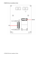
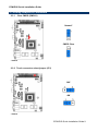
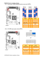
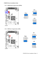
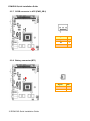
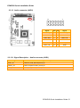
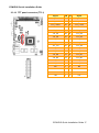
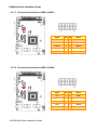
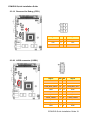
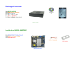
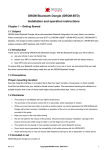
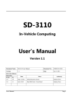
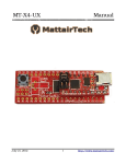
ECM-DX2 DX&P Vortex86DX2 3.5” Micro Module Quick Installation Guide 1st Ed – 25 December 2013 Part No. E2017391800R ECM-DX2 Quick Installation Guide FCC Statement THIS DEVICE COMPLIES WITH PART 15 FCC RULES. OPERATION IS SUBJECT TO THE FOLLOWING TWO CONDITIONS: (1) THIS DEVICE MAY NOT CAUSE HARMFUL INTERFERENCE. (2) THIS DEVICE MUST ACCEPT ANY INTERFERENCE RECEIVED INCLUDING INTERFERENCE THAT MAY CAUSE UNDESIRED OPERATION. THIS EQUIPMENT HAS BEEN TESTED AND FOUND TO COMPLY WITH THE LIMITS FOR A CLASS "A" DIGITAL DEVICE, PURSUANT TO PART 15 OF THE FCC RULES. THESE LIMITS ARE DESIGNED TO PROVIDE REASONABLE PROTECTION AGAINST HARMFUL INTERFERENCE WHEN THE EQUIPMENT IS OPERATED IN A COMMERCIAL ENVIRONMENT. THIS EQUIPMENT GENERATES, USES, AND CAN RADIATE RADIO FREQUENCY ENERGY AND, IF NOT INSTATLLED AND USED IN ACCORDANCE WITH THE INSTRUCTION MANUAL, MAY CAUSE HARMFUL INTERFERENCE TO RADIO COMMUNICATIONS. OPERATION OF THIS EQUIPMENT IN A RESIDENTIAL AREA IS LIKELY TO CAUSE HARMFUL INTERFERENCE IN WHICH CASE THE USER WILL BE REQUIRED TO CORRECT THE INTERFERENCE AT HIS OWN EXPENSE. A Message to the Customer Avalue Customer Services Each and every Avalue’s product is built to the most exacting specifications to ensure reliable performance in the harsh and demanding conditions typical of industrial environments. Whether your new Avalue device is destined for the laboratory or the factory floor, you can be assured that your product will provide the reliability and ease of operation for which the name Avalue has come to be known. Your satisfaction is our primary concern. Here is a guide to Avalue’s customer services. To ensure you get the full benefit of our services, please follow the instructions below carefully. Technical Support We want you to get the maximum performance from your products. So if you run into technical difficulties, we are here to help. For the most frequently asked questions, you can easily find answers in your product documentation. These answers are normally a lot more detailed than the ones we can give over the phone. So please consult the user’s manual first. To receive the latest version of the user’s manual; please visit our Web site at: http://www.avalue.com.tw/ 2 ECM-DX2 Quick Installation Guide ECM-DX2 Quick Installation Guide 1. Getting Started 1.1 Safety Precautions Warning! Always completely disconnect the power cord from your chassis whenever you work with the hardware. Do not make connections while the power is on. Sensitive electronic components can be damaged by sudden power surges. Only experienced electronics personnel should open the PC chassis. Caution! Always ground yourself to remove any static charge before touching the CPU card. Modern electronic devices are very sensitive to static electric charges. As a safety precaution, use a grounding wrist strap at all times. Place all electronic components in a static-dissipative surface or static-shielded bag when they are not in the chassis. 1.2 Packing List Before you begin installing your single board, please make sure that the following materials have been shipped: 1 x 3.5” ECM-DX2 Micro Module 1 x Quick Installation Guide for ECM-DX2 1 x AUX-032 daughter board 1 x DVD-ROM contains the followings: — User’s Manual (this manual in PDF file) — Ethernet driver and utilities — VGA drivers and utilities — Audio drivers and utilities 1 x Cable set contains the followings: — 1 x PS/2 Keyboard & mouse Y cable (6-pin,Mini-DIN) — 1 x Audio cable (12pin,2.0 pitch) — 1 x USB cable (10P/2.0mm-10P/2.0mm) — 1 x Serial ATA cable (7-pin, standard) — 1 x Flat cable 9P(M)-PHD 10P/2.0mm) 3M foam (VHB-4622 10mm*20mm*1.1mm) ECM-DX2 Quick Installation Guide 3 ECM-DX2 Quick Installation Guide 2. Hardware Configuration 4 ECM-DX2 Quick Installation Guide ECM-DX2 Quick Installation Guide 2.1 Product Overview ECM-DX2 Quick Installation Guide 5 ECM-DX2 Quick Installation Guide 6 ECM-DX2 Quick Installation Guide ECM-DX2 Quick Installation Guide 2.2 Jumper and Connector List You can configure your board to match the needs of your application by setting jumpers. A jumper is the simplest kind of electric switch. It consists of two metal pins and a small metal clip (often protected by a plastic cover) that slides over the pins to connect them. To “close” a jumper you connect the pins with the clip. To “open” a jumper you remove the clip. Sometimes a jumper will have three pins, labeled 1, 2, and 3. In this case, you would connect either two pins. The jumper settings are schematically depicted in this manual as follows: A pair of needle-nose pliers may be helpful when working with jumpers. Connectors on the board are linked to external devices such as hard disk drives, a keyboard, or floppy drives. In addition, the board has a number of jumpers that allow you to configure your system to suit your application. If you have any doubts about the best hardware configuration for your application, contact your local distributor or sales representative before you make any changes. The following tables list the function of each of the board’s jumpers and connectors. Jumpers Label Function Note CMOS1 Clear CMOS 3 x 1 header, pitch 2.54 mm FPT1 AT/ ATX Input power select 6 x 2 header, pitch 2.00 mm JP1 Touch connector select jumper 3 x 1 header, pitch 2.00 mm JRI2/3/4 COM 2/3/4 pin 9 signal select 3 x 2 header, pitch 2.00 mm CSET1 Serial port in RS232/422/485 mode connector 6 x 2 header, pitch 2.00 mm Label Function Note TOUCH1 Touch connector 9 x 1 wafer, pitch 2.00 mm BT1 Battery connector 2 x 1 wafer, pitch 1.25 mm Connectors ECM-DX2 Quick Installation Guide 7 ECM-DX2 Quick Installation Guide SPWR1 SATA Power connector 2 x 1 wafer, pitch 2.00 mm PC-104 PC-104 connector 20 x 2 header, pitch 2.54mm PC-104 PC-104 connector 32 x 2 header, pitch 2.54mm JTG1 Reserved for Debug 3 x 2 header, pitch 2.00 mm AUD1 Audio connector 6 x 2 header, pitch 2.00 mm BKL1 LCD inverter connector 5 x 1 wafer, pitch 2.00 mm COM1 Serial port 1 connector D-sub 9-pin, male COM2/3/4 Serial port 2/3/4 connector 5 x 2 header, pitch 2.00 mm DIO1 General purpose I/O connector 6 x 2 header, pitch 2.00 mm TTL1 TFT panel connector 20 x 2 wafer, pitch 1.25 mm VR1 LCD backlight brightness adjustment connector 3 x 1 header, pitch 2.54 mm LVDS1 LVDS connector 10 x 2 wafer, pitch 1.25 mm BPWM1 LCD PWM Mode Selector 2 x 1 header, pitch 2.00mm RS1 Reset button USB1/2 On-board pin header for USB2.0 LAN1/2 RJ-45 Ethernet connector D16 LED connector PWRSB1 5VSB connector in ATX 3 x 1 wafer, pitch 2.54 mm PWR1 Power connector 2 x 2 wafer, pitch 4.20 mm KBMS1 PS/2 keyboard & mouse connector SATA1 Serial ATA connector 1 CN1 VGA connector MPCIE1 Mini-PCI connector CF1 CF card slot 5 x 2 header, pitch 2.00 mm D-sub 15-pin, female Limitation: 1. Attach a modem to COM2/COM3 when the modem power is off would result in OS to be freezed in Windows XP logo. Power on the modem would continue to complete Windows booting process. 2. Text in in DOS might be out of screen at random. 3. Resolution needs to be set correctly in case of screen ambiguity in Windows 2000 after the graphic driver installation. 4. Link LED keeps the same green color in both 10M/100Mbps for DM&P Vortex86DX LAN chip. 5. HDD LED is working functionally when reading/writing CF cards, but fails in SATA devices. 8 ECM-DX2 Quick Installation Guide ECM-DX2 Quick Installation Guide 2.3 Setting Jumpers & Connectors 2.3.1 Clear CMOS (CMOS1) Normal* CMOS Clear * Default 2.3.2 Touch connector select jumper (JP1) 5W* 4W * Default ECM-DX2 Quick Installation Guide 9 ECM-DX2 Quick Installation Guide 2.3.3 Serial port in RS232/422/485 mode connector (CSET1) RS232* Signal * Default RS422 RS485 PIN PIN Signal COM3_M1_EN 12 11 GND +5V 10 9 COM3_M0 SUS_LED# 8 7 COM3_M0_H COM2_M1_EN 6 5 GND +5V 4 3 COM2_M0 NRX2# 2 1 COM2_M0_H 2.3.4 AT/ ATX Input power select (FPT1) ATX* AT Signal * Default 10 ECM-DX2 Quick Installation Guide PIN PIN Signal HDD_LED+ 1 2 PWR_LED+ HDD_LED# 3 4 GND GND 5 6 SUS_LED+ SYS_RST# 7 8 SUS_LED# PWR_BTN# 9 10 PS_ON_EN GND 11 12 GND ECM-DX2 Quick Installation Guide 2.3.5 COM 2/4 pin 9 signal select (JRI2/4) +5V JRI2 JRI4 Ring* +12V * Default 2.3.6 COM 3 pin 9 signal select (JRI3) +5V Ring* +12V * Default ECM-DX2 Quick Installation Guide 11 ECM-DX2 Quick Installation Guide 2.3.7 5VSB connector in ATX (PWR_SB1) Signal PIN PS_ON# 1 NA 2 +5V 3 Signal PIN GND 2 +3.3V 1 2.3.8 Battery connector (BT1) 12 ECM-DX2 Quick Installation Guide ECM-DX2 Quick Installation Guide 2.3.9 Power connector (PWR1) Signal PIN PIN Signal GND 1 2 GND +12V 3 4 +12V 2.3.10 SATA Power connector (SPWR1) Signal PIN GND 1 +5V 2 ECM-DX2 Quick Installation Guide 13 ECM-DX2 Quick Installation Guide 2.3.11 LCD inverter connector (BKL1) Signal PIN +5V 5 BRIGHT 4 TTL_ENBLT 3 GND 2 +12V 1 2.3.12 General purpose I/O connector (DIO1) Signal 14 ECM-DX2 Quick Installation Guide PIN PIN Signal DI0 1 2 DO_TTL0 DI1 3 4 DO_TT1 DI2 5 6 DO_TTL2 DI3 7 8 DO_TTL3 I2C_CLK 9 10 I2C_DAT GND 11 12 +5V ECM-DX2 Quick Installation Guide 2.3.13 Audio connector (AUD1) Signal PIN PIN Signal LINEOUT_R 1 2 LINEOUT_L GND 3 4 GND LINE1-RIN 5 6 LINE1-LIN MIC-RIN 7 8 MIC-LIN FRONT-JD 9 10 LINE1_JD MIC1_JD 11 12 GND 2.3.13.1 Signal Description – Audio connector (AUD1) Signal Signal Description LINE1_JD AUDIO IN (LINE_RIN/LIN)sense pin FRONT_JD AUDIO Out(ROUT/LOUT) sense pin MIC1_JD MIC IN (MIC_RIN/LIN) sense pin ECM-DX2 Quick Installation Guide 15 ECM-DX2 Quick Installation Guide 2.3.14 Serial port 2/3/4 connector (COM2/3/4) COM2 COM3 COM4 Signal PIN PIN Signal NDCD2/3/4# 1 2 NRX2/3/4# NTX2/3/4# 3 4 NDTR2/3/4# GND 5 6 NDSR2/3/4# NRTS2/3/4# 7 8 NCTS2/3/4# NRI2/3/4# 9 10 NC 2.3.15 Touch connector (TOUCH1) 16 ECM-DX2 Quick Installation Guide PIN Signal 4-WIRE 5-WIRE 8-WIRE 1 X+ NC NC Right Sense 2 X- NC NC Left Sense 3 Y+ NC NC Bottom Sense 4 SENSE NC Sense Top Sense 5 X+ Right LR Right Excite 6 X- Left LL Left Excite 7 Y+ Bottom UR Bottom Excite 8 Y- Top UL Top Excite 9 GND GND GND GND ECM-DX2 Quick Installation Guide 2.3.16 TFT panel connector (TTL1) Signal PIN PIN Signal TTL_ENBLT 39 40 TTL_ENVEE TTL_LVDE 37 38 TTL_LVHS TTL_LVCLK 35 36 TTL_LVVS GND 33 34 GND TTL_R6 31 32 TTL_R7 TTL_R4 29 30 TTL_R5 TTL_R2 27 28 TTL_R3 TTL_R0 25 26 TTL_R1 TTL_G6 23 24 TTL_G7 TTL_G4 21 22 TTL_G5 TTL_G2 19 20 TTL_G3 TTL_G0 17 18 TTL_G1 TTL_B6 15 16 TTL_B7 TTL_B4 13 14 TTL_B5 TTL_B2 11 12 TTL_B3 TTL_B0 9 10 TTL_B1 NC 7 8 NC +3V 5 6 +3V GND 3 4 GND +5V 1 2 +5V ECM-DX2 Quick Installation Guide 17 ECM-DX2 Quick Installation Guide 2.3.17 On-board pin header for USB2.0 (USB1) Signal PIN PIN Signal +5V 1 2 GND USB0N 3 4 GND USB0P 5 6 USB1P GND 7 8 USB1N GND 9 10 +5V 2.3.18 On-board pin header for USB2.0 (USB2) Signal 18 ECM-DX2 Quick Installation Guide PIN PIN Signal +5V 1 2 GND USB2N 3 4 GND USB2P 5 6 USB3P GND 7 8 USB3N GND 9 10 +5V ECM-DX2 Quick Installation Guide 2.3.19 Reserved for Debug (JTG1) Signal PIN PIN Signal +5V 1 2 GND TD0 3 4 TCK TDI 5 6 TMS 2.3.20 LVDS connector (LVDS1) Signal PIN PIN Signal +3V 19 20 +5V +3V 17 18 +5V LVDS_DDC_DATA 15 16 LVDS_DDC_CLK GND 13 14 GND LVDS_CLKP 11 12 LVDS_CLKN LVDS_TXD3P 9 10 LVDS_TXD3N LVDS_TXD2P 7 8 LVDS_TXD2N LVDS_TXD1P 5 6 LVDS_TXD1N LVDS_TXD0P 3 4 LVDS_TXD0N GND 1 2 GND ECM-DX2 Quick Installation Guide 19 ECM-DX2 Quick Installation Guide 2.3.21 LCD PWM Mode Selector (BPWM1) Signal PIN BRIGHT 1 PWM_D_BKLTCTRL 2 2.3.22 LCD backlight brightness adjustment connector (VR1) 20 ECM-DX2 Quick Installation Guide Signal PIN +5V 1 BRIGHT 2 GND 3