1
PEYSANJ User's Manual (Novo
Tech Software Ltd)
PEYSANJ User's Manual (Novo Tech Software Ltd)
Table of Contents
1. Peysanj ...............................................................................................................................................................3
2. License Agreement .............................................................................................................................................4
3. Contents .............................................................................................................................................................6
3.1 General Tips and Tricks.................................................................................................................................6
3.2 How to Change Units System?......................................................................................................................6
3.3 Your License Info. .........................................................................................................................................7
3.4 Peysanj Main Screen ....................................................................................................................................7
3.5 Project List ..................................................................................................................................................10
3.6 Engineering Analysis ...................................................................................................................................11
3.6.1 Bearing Capacity ..................................................................................................................................11
3.6.2 Soil Liquefaction ..................................................................................................................................15
3.6.3 Plate Loading Test ...............................................................................................................................17
3.6.4 Pressure-meter Test ............................................................................................................................17
3.6.5 Slope Stability ......................................................................................................................................17
3.6.6 Lateral Earth Pressure Coefficients ......................................................................................................19
3.6.7 Stress Distribution ...............................................................................................................................20
3.6.8 Retaining Wall Pressure .......................................................................................................................21
3.6.9 Ks Conversion ......................................................................................................................................23
3.7 Calculation Details ......................................................................................................................................24
3.8 Print Preview ..............................................................................................................................................24
3.9 Working with Graphs ..................................................................................................................................27
3.10 Options and Settings ................................................................................................................................28
4. Theory ..............................................................................................................................................................36
4.1 Bearing Capacity .........................................................................................................................................36
4.2 Soi Liquefaction ..........................................................................................................................................37
4.2.1 Introduction.........................................................................................................................................37
4.2.2 Cyclic Stress Ratio (CSR) .......................................................................................................................38
4.2.3 Magnitude Sclaing Factor (MSF) ..........................................................................................................39
4.2.4 Stress Reduction Factor .......................................................................................................................39
4.2.5 Cyclic Resistance Ratio (CRR) ...............................................................................................................40
4.2.6 Post Liquefaction Movements .............................................................................................................48
1
PEYSANJ User's Manual (Novo Tech Software Ltd)
5. Online Resources ..............................................................................................................................................51
5.1 Novo Tech Website ....................................................................................................................................51
5.2 PEYSANJ Updates .......................................................................................................................................51
5.3 Other Programs ..........................................................................................................................................51
5.4 Contact Us ..................................................................................................................................................51
2
PEYSANJ User's Manual (Novo Tech Software Ltd)
1. Peysanj
About
PEYSANJ is a bundle of powerful geotechnical tools for bearing capacity, soil liquefaction, pressure
meter test, etc designed and developed by Novo Tech Software Ltd. For more information please
visit our website.
Novo Tech Software Ltd.
4188 Hoskins Road,
North Vancouver
BC, Canada
Designed and Developed by:
Alireza Afkhami, M.A.Sc, M.C.P, P.Eng
3
PEYSANJ User's Manual (Novo Tech Software Ltd)
2. License Agreement
PEYSANJ End User License Agreement
PLEASE READ THIS END USER LICENSE AGREEMENT ("EULA") CAREFULLY BEFORE
DOWNLOADING OR USING THE SOFTWARE. BY DOWNLOADING THE SOFTWARE, OR USING THE
SOFTWARE, YOU ARE CONSENTING TO BE BOUND BY THIS AGREEMENT. IF YOU DO NOT AGREE
TO ALL OF THE TERMS OF THIS AGREEMENT DO NOT DOWNLOAD AND/OR USE THE SOFTWARE.
The Product is Copyright © 2008-2014 “NOVO TECH SOFTWARE”. You may use it and distribute it
according to this following License Agreement. If you do not agree with these terms, please
remove the Product from your system. By incorporating the Product in your work or distributing
the Product to others you implicitly agree to these license terms.
1. DEFINITIONS
1.1. "PEYSANJ" or "Software" refers to “NOVO TECH SOFTWARE”’s program, in each case,
supplied by “NOVO TECH SOFTWARE” herewith, and corresponding documentation, associated
media, and online or electronic documentation.
1.2. "Trial Version” means a free version of the Software for personal use only, so identified, to be
used in one computer only and for a period of 14 days. The Trial Version is fully functional with no
restrictions compared to the registered version.
1.3. "Registered Version" means a version which has been bought from “NOVO TECH SOFTWARE”.
2. LIMITATION OF LIABILITY
In no event shall "NOVO TECH SOFTWARE" be liable for any damages (including, without
limitation, lost profits, business interruption, or lost information) rising out of 'Authorized Users'
use of or inability to use the PEYSANJ, even if "NOVO TECH SOFTWARE" has been advised of the
possibility of such damages. In no event will "NOVO TECH SOFTWARE" be liable for loss of data or
for indirect, special, incidental, consequential (including lost profit), or other damages based in
contract, tort or otherwise. "NOVO TECH SOFTWARE" shall have no liability with respect to the
content of the PEYSANJ or any part thereof, including but not limited to errors or omissions
contained therein, libel, infringements of rights of publicity, privacy, trademark rights, business
interruption, personal injury, loss of privacy, moral rights or the disclosure of confidential
information.
3. FOR PEYSANJ TRIAL VERSION
(a) The PEYSANJ Trial version may be freely distributed, with exceptions noted below, provided
the distribution package is not modified in ANY WAY.
(b) The PEYSANJ Trial version may not be distributed inside of any other software package
without written permission of “NOVO TECH SOFTWARE”.
(c) The PEYSANJ Trial version allows the user to publish its work according to the license
agreement, but nor “NOVO TECH SOFTWARE” nor any member of the company can be held liable
for the content or accuracy of the publication.
(d) You may use the accompanying Product free of charge for a period of 14 days for the sole
purpose of evaluating the Product. If, after this period, you wish to continue using this Product,
you are required to purchase it. In other case, you are required to remove this Product, in its
4
PEYSANJ User's Manual (Novo Tech Software Ltd)
entirety, from all computers on which it is installed.
(e) You shall not use, copy, rent, lease, sell, modify, decompile, disassemble, otherwise reverse
engineer, or transfer the Product except as provided in this Agreement. Any such unauthorized
use shall result in immediate and automatic termination of this Agreement.
4. FOR PEYSANJ REGISTERED VERSION
(a) You may install and use the Software on a single computer; OR install and store the Software
on a storage device, such as a network server, used only to install the Software on your other
computers over an internal network, provided you have a license for each separate computer on
which the Software is installed and run. A license for the Software may not be shared, installed or
used concurrently on different computers.
(b) The PEYSANJ Registered version allows the registered user to publish its work according to the
license agreement, but nor “NOVO TECH SOFTWARE” nor any member of the company can be
held liable for the content or accuracy of the publication.
(c) The PEYSANJ Registered version guaranties to the registered user free updates for a whole
version cycle and for 12 (twelve) months.
(d) You shall not use, copy, rent, lease, sell, modify, decompile, disassemble, otherwise reverse
engineer, or transfer the Product except as provided in this Agreement. Any such unauthorized
use shall result in immediate and automatic termination of this Agreement.
(e) Once purchased, the Software may not be return to "NOVO TECH SOFTWARE". The price paid
for the Software is not refundable.
(f) The PEYSANJ license is issued for one computer based on the Hardware ID provided by user.
Each transfer of license to another computer, if approved by NOVO TECH SOFTWARE, will be
subject to 20 percent charge based on latest PEYSANJ price.
5. TERMS
This license is effective until terminated. You may terminate it by destroying the program, the
documentation and copies thereof. This license will also terminate if you fail to comply with any
terms or conditions of this agreement. You agree upon such termination to destroy all copies of
the program and of the documentation, or return them to the author.
6. OTHER RIGHTS AND RESTRICTIONS
All other rights and restrictions not specifically granted in this license are reserved by "NOVO
TECH SOFTWARE". If you have any questions regarding this agreement, please write to
[email protected]
YOU ACKNOWLEDGE THAT YOU HAVE READ THIS AGREEMENT, UNDERSTAND IT AND AGREE TO
BE BOUND BY ITS TERMS AND CONDITIONS.
5
PEYSANJ User's Manual (Novo Tech Software Ltd)
3. Contents
3.1 General Tips and Tricks
We recommend minimum 1024*768 screen resolution for using PEYSANJ.
If you are using the dongle key version, please make sure that it is plugged in before you run
the program.
To invoke the help, please press
Make
sure
you
prepare
button on top-right corner of each page.
backup
from
your
data
periodically.
Your
database
is
the
PEYSANJ4.MDB file (see more(See 3.10)).
After each installation, please open the "Options" page and set the default parameters and
choose your favourite analyses methods. This is a very important step in PEYSANJ installation and
setup, otherwise you may end up with incorrect results.
You can print, zoom, set the scales and do more with charts. To activate a chart, simply doubleclick on it. A new dialog will appear which allows you to configure the look of the chart as well as
saving the chart as image files, printing the graph, etc.
Please contact us at [email protected] if you had any questions or suggestions.
How to use the main toolbar(See 3.4)
Working with graphs(See 3.4)
Print preview page features(See 3.8)
3.2 How to Change Units System?
Peysanj supports both Metric and English unit systems. In order to set the units system, select
the Tools tab from the top toolbar and click on Units System button. A new page will popup;
choose the units from the list located at the bottom of the page (see more(See 3.10)).
How to use the main toolbar(See 3.4)
Working with graphs(See 3.4)
Print preview page features(See 3.8)
6
PEYSANJ User's Manual (Novo Tech Software Ltd)
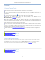
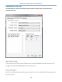
3.3 Your License Info.
The information you provided to us during your purchase, will be stored in your License File and is
used in report headers (top of each page / first page). You can check your License information by
clicking on HelpLicense Manager menu as shown below:
If you have purchased the software but not yet received a license file from Novo Tech, please click
on Request Your License! button and follow the instructions to request a license file. When you
receive the license file (*.license), please click on Install License File button on this dialog to load
and activate the license (program simply copies the license file into the installation folder, you can
do this manually as well).
You can also use this dialog to De-activate your license (in case of license transfer).
How to use the main toolbar(See 3.4)
Working with graphs(See 3.4)
Print preview page features(See 3.8)
3.4 Peysanj Main Screen
This is the main page of PEYSANJ and provides so many features through menus and toolbars.
Each part of this page is illustrated below:
7
PEYSANJ User's Manual (Novo Tech Software Ltd)
Toolbar (Ribbon)
The toolbar provides you the access to load/save projects, performing the calculations, accessing
the help file, etc. Different tabs are illustrated in the following sections:
Project tab
8
PEYSANJ User's Manual (Novo Tech Software Ltd)
Analysis tab
Tools tab
Body
Most of the PEYSANJ analyses are opened in this part of the page. Multiple pages can be opened
in this part of the screen.
Statusbar
This partof the screen provides you more information about the license and selected units system.
In addition if a new version of Peysanj is available, a message will be shown in the middle panel.
How to use the main toolbar
9
PEYSANJ User's Manual (Novo Tech Software Ltd)
Working with graphs
Print preview page features(See 3.8)
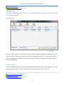
3.5 Project List
This page can be accessed from the Project » Load toolbar button, and lists all the projects saved
in the PEYSANJ database:
In order to load a project, first select the type of analysis (Bearing Capacity, Plate Load Test, etc)
from the toolbar. Then simply select the project on the table and click on "Load Project" button. If
any of the project's information such as client name or address is edited, click on Save button to
store the information.
Deleting a Project
In orderto delete a project along with all its corresponding data click on Delete Project link on the
bottom-left portion of the page. Please notice that this action can not be reverted.
How to use the main toolbar(See 3.4)
Working with graphs(See 3.4)
Print preview page features(See 3.8)
10
PEYSANJ User's Manual (Novo Tech Software Ltd)
3.6 Engineering Analysis
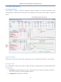
3.6.1 Bearing Capacity
This module is used to calculate allowable bearing capacity of shallow foundations with
simultaneously checking both shear failure and settlement. Each part of this page is explained
below.
Project Information
Please enter project title, client name, project code, etc. This data will be shown on your reports.
Soil Layers Table
Your stratigraphy model may contain unlimited soil layers. Please specify the following parameters
for each layer:
Soil Layer: simple description for layer. This field is only for user's information and does
not have any effect on bearing capacity analysis
C (kg/cm2): Coefficient of cohesion
11
PEYSANJ User's Manual (Novo Tech Software Ltd)
F (deg): Internal angle of friction (between zero and 45 degrees)
Es (kg/cm2): Modulus of elasticity
v: Poisson ratio (between zero and 0.5)
g (gr/cm3): Wet unit weight
Z1 (m): top depth of the layer
Z2 (m): bottom depth of the layer. There should be no gap between layers, so Z1 for this
layer should be same as Z2 for layer above. For the last layer use a very large number like
1000m to assure that stress bulb would not pass the bottom of your model.
Su (kg/cm2): Undrained shear strength. This parameter should only be entered when
F=0; based on Hanson bearing capacity theory, when F=0 then Su will be considered for
shear failure analysis.
Cc , Cs: Consolidation compression and re-compression indexes. They should only be
entered when you want the consolidation settlement to be calculated for this layer. If these
parameters are entered but water level is below this layer, unsaturated consolidation
settlement will be calculated for this layer (Su unsaturated=Susaturated*a where a is a factor less
than one). You may specify a in "Analysis Parameters" frame.
Pc (kg/cm2): Pre-consolidation stress for consolidation settlement
eo: Void ratio
Pre-consolidated: Only select this option if your layer is pre consolidated
To delete a layer, click on row-header to select the whole row, and then press DELETE key on
your keyboard.
If there is a bedrock in your model, only enter soil layers, when program computes the stress
bulbs, no settlement will be calculated beyond the defined soil layers.
It is recommended to press Save button on toolbar right after you entered the data. Then close
the form and re-open it from Projects page.
In this section, ground water level and wet unit weight for soil above the foundation level should
be specified. Please notice that ground water level is measured from underneath the footing
(always positive number).
Analysis Settings
This section contains parameters which are very important for bearing capacity analysis:
Allowable Settlement (cm): this amount is usually one inch (25.4mm) for pad/strip
footings.
Er/Es: is the ratio of modulus of elasticity of re-loading (Er) to loading (Es) part. The best
way to estimate the Er is to use the Plate Loading Test; at the beginning of second cycle of
this test, the slope of the stress-deformation curve (Er) is comparatively sharper than
12
PEYSANJ User's Manual (Novo Tech Software Ltd)
normal slope of the curve (Es). PEYSANJ uses this Er/Es ratio to apply the stress history
effect on the elastic settlement. For example if your footing Df=1m and g=2gr/cm3 then
gDf~0.2kg/cm2 so during elastic settlement analysis, PEYSANJ will use Er for stress range
0 to 0.2 kg/cm2 and thereafter Es is used for analysis.
Rigidity Factor (Ir): This factor is less than zero and depends on rigidity of the footing
(usually 0.9 to 1). PEYSANJ applies this factor to total settlement: S=(Se+Sc)*Ir where Se
and Sc are elastic and consolidation settlements, respectively.
Factor: this factor is used for calculation of un-saturated consolidation settlement. If a
fine-grained layer is unsaturated (e.g. S=80%), then the actual consolidation settlement is
a fraction of calculated saturated consolidation settlement. Please specify this parameter
(between zero and unity).
Safety Factor: this parameter is applied to shear failure of the soil below the footing.
Foundation Size
Shape: you may choose among "Pad/Strip", "Raft/Spread" and "Circular" foundations.
Size ratio (L/B): is used to specify the length to width ratio of the footing.
Df : is the height of the soil around and above the footing (affects the shear failure)
D : depth of placement of the foundation (usually depth of excavation).
MB, ML: The bending moment applied on the footing
HB, HL: The horizontal forces applied to the footing
V : The vertical force applied on the footing
Note : for raft footings consider Df and D the same as excavation depth.
How to see the calculation results?
Please press Calculate button on the toolbar when you entered all input parameters. Then click on
each tab to see the corresponding chart. By clicking on each chart, more options will be available
including export to Excel and image formats.
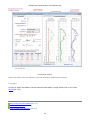
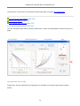
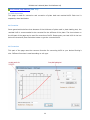
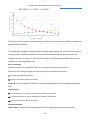
Pad/Strip footings outputs
For this type of footings, two charts are provided:
Bearing Capacity chart
Includes 3 curves; for all of them vertical axis is the allowable stress and horizontal axis is the
foundation width (B); please note that, you have already entered L/B ratio so as B increases, the
chart covers various foundation sizes:
Shear Failure Curve (blue): Only encompasses the shear failure criteria for the model.
Allowable Settlement Curve (purple): This curve shows the allowable stress, provided
that the total settlement is around the allowable settlement already introduced by the
user.
13
PEYSANJ User's Manual (Novo Tech Software Ltd)
Allowable Bearing Capacity Curve (green): This curve is the lower intersection of two
above-mentioned curves and assures that on each point along the curve, both settlement
and shear failures are within the allowable limits.
Settlement chart: includes 3 curves representing Immediate (elastic), Consolidation and Total
settlements. Please be advised that these settlement values are calculated based on allowable
bearing capacity calculated for that specific footing.
Raft foundations output
For raft foundations since the size is considerable, shear failure
is not usually an issue and restricting the settlement to allowable amount, controls the allowable
bearing capacity. Based on user-defined allowable settlement for this footing, the corresponding
allowable stress is picked from the settlement plot and is shown on a box.
Exporting the results to Excel
Click on the Excel tab in the bearing capacity page. This will generate an Excel file containing all
Allowable bearing capacity and settlement values for various L/B ratios and different foundation
widths (B). The width range and L/B ratios can be specified in the Option page.
1. To generate the Excel file, please click on "Export to Excel" button on Excel tab. This will
take few minutes to prepare the file. Please be patient.
14
PEYSANJ User's Manual (Novo Tech Software Ltd)
2. When you prompt to open the Excel file, please select Yes. When Excel opens the file click
on the tabs below the page to view the charts or calculation summary.
3. You can easily copy and past all charts into your other Windows applications
(such as Word). please click on top-left corner of charts and right-click.
Then choose Copy from the popup menu. Now you just need to paste the
chart into your destination program (such as Word).
Printing the results
Press Print button from the toolbar to see the calculation details and the report.
How to use the main toolbar(See 3.4)
Working with graphs(See 3.4)
Print preview page features(See 3.8)
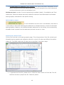
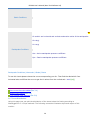
3.6.2 Soil Liquefaction
This module is used to calculate safety factor against soil liquefaction along with estimated postliquefaction displacements and residual strength. As illustrated below, please enter site data,
liquefaction triggering criteria and field test data, then click on Calculate button from the top
toolbar. The results will be shown on the right side of the page in the form of various plots.
15
PEYSANJ User's Manual (Novo Tech Software Ltd)
Printing the results
Press Print button from the toolbar to see the calculation details and the report.
The graphs
In order to obtain the details of stress values at each depth, simply double click on the chart
(more(See 3.9)).
How to use the main toolbar(See 3.4)
Working with graphs(See 3.4)
Print preview page features(See 3.8)
16
PEYSANJ User's Manual (Novo Tech Software Ltd)
3.6.3 Plate Loading Test
This page is designed for calculating plate loading test. Please enter all 3 settlement gauge
readings and press Calculate button from the top toolbar. Modulus of subgrade reaction for each
cycle of loading-unloading will be calculated separately and will be presented in the table.
Printing the results
Press Print button from the toolbar to see the calculation details and the report.
How to use the main toolbar(See 3.4)
Working with graphs(See 3.4)
Print preview page features(See 3.8)
3.6.4 Pressure-meter Test
This page is designed for calculating pressure meter test. Please enter calibration data and test
data (including pressure and volume pairs); then press Calculate button from the top toolbar.
Menard modulus (Em) and limit pressure (Pl) will be calculated and presented in the table.
Printing the results
Press Print button from the toolbar to see the calculation details and the report.
How to use the main toolbar(See 3.4)
Working with graphs(See 3.4)
Print preview page features(See 3.8)
3.6.5 Slope Stability
Using this page user can roughly estimate the stable slope based on the design table proposed by
Fang. This table is calculated based on limit equilibrium analysis and should be only used as a
rough estimate since it does not many parameters such as groundwter level, surchage, etc.
17
PEYSANJ User's Manual (Novo Tech Software Ltd)
Soil and Slope Parameters
Enter soil friction angle, unit weight and cohesion along with slope height and backslope angle. Please
notice that safety factor will be applied on Tan(). Press Calculate button when all fields entered.
Stability Factor and
Ns or stability factor is calculated based on slope height (H), soil unit weight () and soil cohesion (C)
as shown below:
18
PEYSANJ User's Manual (Novo Tech Software Ltd)
This parameter is a key factor for estimating the stable slope angle, according to this methodology.
How to use the main toolbar(See
3.4)
Working with graphs(See
3.4)
Print preview page features(See 3.8)
3.6.6 Lateral Earth Pressure Coefficients
You can calculate lateral earth pressure coefficients in static and earthquake conditions using this
page.
Wall geometry and soil data
Please enter the soil parameters and geometry as specified in the legend and press Calculate
button.
19
PEYSANJ User's Manual (Novo Tech Software Ltd)
Static Conditions
Mo
Kh and Kv are horizontal and vertical acceleration ratios of the earthquake:
Kh=ah/g
Kv=av/g
Earthquake Conditions
Kae : Active earthquake pressure coefficient
Kpe : Passive earthquake pressure coefficient
Earthquake Conditions (Mononobe / Okabe) Charts
To use this charts please choose the curve corresponding your Kv. Then find the desired Kh from
horizontal axis and follow the curve to get the K values from the vertical axis.
How to use the main toolbar(See 3.4)
Working with graphs(See 3.4)
Print preview page features(See 3.8)
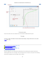
3.6.7 Stress Distribution
Using this page user can plot the distribution of the stress below the footing according to
Westerggard or 2:1 Slope methods. The following screenshot illustrates input and output of this
module:
20
PEYSANJ User's Manual (Novo Tech Software Ltd)
Printing the results
Press Print button from the toolbar to see the calculation details and the report.
The graph
In order to obtain the details of stress values at each depth, simply double click on the chart
(more(See 3.9)).
How to use the main toolbar(See
3.4)
Working with graphs(See
3.4)
Print preview page features(See 3.8)
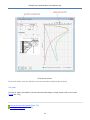
3.6.8 Retaining Wall Pressure
Using this page user can calcularte the distribution of the lateral earth pressure behind the
retaining walls due to the surcharge. This surcharge can be line load or strip load. The following
screenshot illustrates input and output of this module:
21
PEYSANJ User's Manual (Novo Tech Software Ltd)
Printing the results
Press Print button from the toolbar to see the calculation details and the report.
The graph
In order to obtain the details of stress values at each depth, simply double click on the chart
(more(See 3.9)).
How to use the main toolbar(See
Working with graphs(See
3.4)
3.4)
22
PEYSANJ User's Manual (Novo Tech Software Ltd)
Print preview page features(See
3.8)
3.6.9 Ks Conversion
This page is used for conversion and correction of plate load test resulted Ks30. Each tool is
separately described below:
Ks Correction
Some geoscientists believe that because of the thickness of plate used in plate loading test, the
resulted Ks30 is recommended to be corrected for the stiffness of the plate. The chart shown on
the left part of the page can be used for correction of Ks30. Please enter your test Ks30 in the box
below the chart and press Calculate button to get the corrected Ks30.
Ks Conversion
This part of the page uses the common formulas for converting Ks30 to your desired footing's
size. Different formulas is used according to soil type.
23
PEYSANJ User's Manual (Novo Tech Software Ltd)
How to use the main toolbar(See 3.4)
Working with graphs(See 3.4)
Print preview page features(See 3.8)
3.7 Calculation Details
As a general rule, all calculations in PEYSANJ come with step-by-step calculation details. Please
press "Calculation Details" button on toolbar after performing the calculations. This will show
another page containing the details. If you desire to print a report, click on "Print" button on the
toolbar to open the Print Preview(See 3.8) page. A report comprises:
Cover page
Assumptions: including all input data and other applicable assumptions
Details: including step-by-step details of the calculations
Plots: including all graphs
This report may be saved and exported to various formats such as Microsoft Excel, PDF, etc.
How to use the main toolbar(See 3.4)
Working with graphs(See 3.4)
Print preview page features(See 3.8)
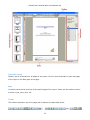
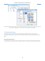
3.8 Print Preview
This page will be shown when you click on Print button from the toolbar. Different parts of the
page are described below:
24
PEYSANJ User's Manual (Novo Tech Software Ltd)
Thumbnail Preview
Shows a set of thumbnails for all pages of the report. Click on each thumbnail to open that page
of the report in the Body part of the page.
Body
Is used to show the full preview of the specific page of the report. Please use the toolbar buttons
to zoom in/out, save, print, etc
Toolbar
This toolbar located on top of the page and its buttons are described below:
25
PEYSANJ User's Manual (Novo Tech Software Ltd)
Opens a report file which is already saved under
c1d format
Is used to save the current report with XLS, PDF,
HTML, or even image formats such as JPG, BMP,
TIFF, PNG, etc. Some limitations apply to this
feature.
Used to adjust the page setup such as margins,
etc.
Click on this button to print the report
This will redraw the whole report again
Sets the view of report by showing 1, 2 and 4
pages of the report within the Body part of the
viewer.
Used to navigate among the report pages. Enter
the exact page number in the box to jump to that
page.
Used for zoom
Used for pan (moving the preview page). Hold your
left mouse button and move the page.
If you click on this button, you will be able to
select a text within the report. This feature can be
used to copy a text from the report for use in
another Windows application such as Microsoft
Word.
Use this button to find a phrase in the report.
Search Panel
Enter the searching phrase in this panel and click the Search button. A list will be populated with
all pages containing your search criteria. Click on each item to browse to that page.
How to use the main toolbar(See 3.4)
26
PEYSANJ User's Manual (Novo Tech Software Ltd)
Working with graphs(See 3.4)
Print preview page features(See 3.8)
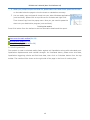
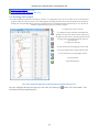
3.9 Working with Graphs
We understand that presentation of the analysis results is very important to our users. Everywhere in Novo Tech Software
programs when you click on a chart, a new dialog appears containing the chart and its associated data. In the following
example, the corresponding dataset is shown on right and can be scrolled horizontally and vertically to view all data. In
addition, toolbar buttons provide you with more features:
To change line styles of the plot
To change the scale (minimum, maximum and
gridlines) of each axis. Please click on small arrow
on right side of the icon to open the dropdown menu
To toggle between normal/logarithmic scale for
horizontal axis
To change the chart type
To open the advanced settings page for the chart
To save the dataset table as Microsoft Excel file
To save the chart as text and graphic format
To print the chart
Opens this help page
How can I change the appearance of the chart such as legend, chart type, etc?
You can configure almost everything in the chart by clicking on
will open the following dialog box:
27
button from the toolbar. This
PEYSANJ User's Manual (Novo Tech Software Ltd)
Click on the desired element from the list located on the left side of the page; more options will be
shown on the right portion. Click on OK button to apply your changes.
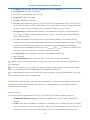
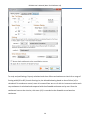
3.10 Options and Settings
The Options page provides access to analysis settings and default values used during the
calculations and analyses. As shown in the following screenshot, settings are grouped into three
tabs:
Bearing Capacity tab
This tab allows user defining the analysis methods used for the calculation of bearing and settlement.
28
PEYSANJ User's Manual (Novo Tech Software Ltd)
For strip and pad footings, Peysanj calculates both shear failure and settlement criteria for a range of
footing width (B1 to B2). At each footing size, the allowable bearing based on shear failure (1) is
calculated. For settlement control, stress is increased from zero to 1 with increments and at each
step settlement is calculated and compared with the allowable settlement set by user. Once the
settlement has met the criterion, this stress (2) is recorded as the allowable stress based on
settlement.
29
PEYSANJ User's Manual (Novo Tech Software Ltd)
Then 1 and 2 are compared at each footing size, and minimum of these two values is introduced as
allowable bearing capacity.
For spread (mat) foundations, however, due to relatively larger footing size, shear failure will not be a
limiting criterion. Therefore settlement of the footing is calculated and plotted versus stress. This
stress can be set to vary from 1 to 2 with increment. The following sections describe how this
procedure can be configured by user:
Strip / Pad Footing:
From: the minimum footing width (B1) used for bearing capacity and settlement calculation
To: the maximum footing width (B2) used for bearing capacity and settlement calculation
: the width step used for calculation
: the stress increment used for calculation
Excel L/B: a list of maximum 5 L/B ratios for which bearing capacity charts are exported to Microsoft
Excel
Spread Footing:
: the minimum stress for which settlement of foundation is calculated
: the maximum stress for which settlement of foundation is calculated
: the stress increment used for calculation
Calculation Methods:
Shear Failure: Peysanj calculates bearing capacity of the footings based on Hansen equations.
30
PEYSANJ User's Manual (Novo Tech Software Ltd)
Elastic: Three methods can be chosen for elastic (immediate) settlement calculation of footings. For
further reference and detailed description of each methodology please refer to reference books.
Consolidation: for the purpose of calculating 1-D Terzaghi consolidation settlement, stress increase
dP is calculated at the top, middle and the bottom of the layer and an average is calculated
Pave=(pt+4Pm+Pb)/6
Settings:
If "Goodier and Timoshenko" method is chosen for elastic settlement calculation, then stress
influence depth H should be calculated first. In this section user can choose how H is calculated.
Usually H is taken as the depth in which P is reached X percent of the stress below footing, where X
can be set by user.
Stress Distribution Methods:
User can set the stress distribution methods for calculation of elastic and consolidation settlements.
Ignore Elastic Settle.... : If this options is selected by user, during the calculation of total settlement of
the footing, if consolidation settlement is present for a layer, the elastic settlement will be ignored in
that layer. In general, the total settlement is defined as below in Peysanj software:
S = Ir (Se+.Sc)
where:
Ir : Rigidity factor (between zero and one; usually more than 0.9). The idea is to allow a rigid
foundation to decrease the total settlement due to its ability to uniformly spread the stress.
Se : Elastic settlement
Sc: Consolidation settlement
: User can specify what percentage of consolidation settlement should be considered in the total
settlement calculation. The default value is 1. However, user can choose a lower value if the layer
is not saturated to account for lower moisture contents in clay/silt layer.
Apply Rb in 3rd term.... : If this option is selected selected Rb = 1 - 0.25 Log(0.5B) will be
applied to the 3rd term of Hansen bearing capacity formula.
31
PEYSANJ User's Manual (Novo Tech Software Ltd)
Liquefaction & PMT tab
This tab allows user defining the analysis methods used for the calculation of liquefaction and
pressure-meter test.
Apply All SPT Corrections:
If selected by user, SPT blow counts will be corrects during soil liquefaction analysis based on user's
settings. It is assumed that N60 numbers are entered by user.
Pressure-meter Probes:
Here is a list of default probes used for pressure-meter test. User can expand this list by adding more
probes to the list.
32
PEYSANJ User's Manual (Novo Tech Software Ltd)
Custom Settings:
Although not every user may use this feature, it is possible to edit custom.txt file (copied in the
Peysanj installation folder) and change the value of these two parameters:
ignore_depth_factors : If set to True, all depth factors will be considered =1 during bearing capacity
analysis.
ignore_fox_index_if : If set to True, the Fox factor (If) used for reduction of settlement in Goodier &
Timoshenko method, will be assumed =1 during settlement analysis.
Advanced tab
This tab allows user to configure and prepare backup from Peysanj database file, as well as choosing
the user-interface language and units.
33
PEYSANJ User's Manual (Novo Tech Software Ltd)
Database Path:
Peysanj database file is a Microsoft Access file stored in the path shown by "Access database path".
The database file (PEYSANJ4.MDB) contains all your projects information and calculations. So, it is
very important to prepare periodic backup from your database.
How to prepare a backup? Click on "Prepare Backup Copy" link and specify the location on your hard
drive where you want the backup file (PEYSANJ4.MDB) to be copied. When the backup file is
prepared, simply copy it to your flash drive, burn on CD, etc. and keep in a safe place.
How to restore a database? if you want to restore a database, click on ... button next to the path, and
select the database file. This will replace the existing database.
34
PEYSANJ User's Manual (Novo Tech Software Ltd)
Company Information:
This allows user to select company logo, enter address and company name. This information is used
in the reports.
View Activity Log:
This will show a list of Peysanj users activities such as Save, Delete, Print, etc. during working with the
program.
Language:
Currently only English and Farsi are available. Select your language and re-run the program for this
setting to take effect.
Units:
Three unit systems are available in Peysanj. Select your units and re-run the program for this setting
to take effect.
How to use the main toolbar(See 3.4)
Working with graphs(See 3.4)
Print preview page features(See 3.8)
35
PEYSANJ User's Manual (Novo Tech Software Ltd)
4. Theory
4.1 Bearing Capacity
For strip and pad footings, Peysanj calculates both shear failure and settlement criteria for a range of
footing width (B1 to B2). At each footing size, the allowable bearing based on shear failure (1) is
calculated. For settlement control, stress is increased from zero to 1 with increments and at each
step settlement is calculated and compared with the allowable settlement set by user. Once the
settlement has met the criterion, this stress (2) is recorded as the allowable stress based on
settlement.
Then 1 and 2 are compared at each footing size, and minimum of these two values is introduced as
allowable bearing capacity.
For spread (mat) foundations, however, due to relatively larger footing size, shear failure will not be a
limiting criterion. Therefore settlement of the footing is calculated and plotted versus stress. This
stress can be set to vary from 1 to 2 with increment. This procedure can be configured by user
through Options page(See 3.10). Peysanj performs bearing capacity analysis of the footings based on
Hansen equations. Three methods can be chosen for elastic (immediate) settlement calculation of
footings. For further reference and detailed description of each methodology please refer to
reference books. For the purpose of calculating 1-D Terzaghi consolidation settlement, stress increase
dP is calculated at the top, middle and the bottom of the layer and an average is calculated
Pave=(pt+4Pm+Pb)/6
36
PEYSANJ User's Manual (Novo Tech Software Ltd)
If "Goodier and Timoshenko" method is chosen for elastic settlement calculation, then stress
influence depth H should be calculated first. In this section user can choose how H is calculated.
Usually H is taken as the depth in which P is reached X percent of the stress below footing, where X
can be set by user. In general, the total settlement is defined as below in Peysanj software:
S = Ir (Se+.Sc)
where:
Ir : Rigidity factor (between zero and one; usually more than 0.9). The idea is to allow a rigid
foundation to decrease the total settlement due to its ability to uniformly spread the stress.
Se : Elastic settlement
Sc: Consolidation settlement
: User can specify what percentage of consolidation settlement should be considered in the total
settlement calculation. The default value is 1. However, user can choose a lower value if the layer
is not saturated to account for lower moisture contents in clay/silt layer.
How to use the main toolbar(See 3.4)
Working with graphs(See 3.4)
Print preview page features(See 3.8)
4.2 Soi Liquefaction
4.2.1 Introduction
Soil liquefaction and related ground failures are commonly associated with large earthquakes. In
common usage, liquefaction refers to the loss of strength in saturated, cohesion-less soils due to
the build-up of pore water pressures during dynamic loading. Sladen et al. (1985) defined
liquefaction as:
"Liquefaction is a phenomenon wherein a mass of soil loses a large percentage of
its shear resistance, when subjected to monotonic, cyclic, or shock loading, and
flows in a manner resembling a liquid until the shear stresses acting on the mass
are as low as the reduced shear resistance"
Liquefaction Assessment
Evaluating the liquefaction resistance of soils is an important step in the engineering design of
new structures and the retrofit of existing structures in earthquake-prone regions. The evaluation
37
PEYSANJ User's Manual (Novo Tech Software Ltd)
procedure widely used throughout the world is termed the simplified procedure. This simplified
procedure was originally developed by Seed and Idriss (1971) using blow counts from the
Standard Penetration Test (SPT) correlated with a parameter representing the seismic loading on
the soil, called the Cyclic Stress Ratio (CSR). This parameter is compared to Cyclic Resistance
Ratio (CRR) of the soil and if it exceeds CRR, the soil is likely to be liquefied. A safety factor
against liquefaction is defined as ratio of CRR to CSR:
Safety Factor = CRR / CSR * K * K
CRR = CRR7.5(ave) * MSF
Where:
CRR7.5(ave) :calculated cyclic resistance ratio (average of all selected methods at a desired depth)
for an earthquake with M=7.5
MSF : Magnitude Scaling Factor
K : overburden stress correction factor; only applied to the following analysis methods (see
details(See 4.2.5.1)):
- Vancouver Task Force Report (2007)
- NCEER (1996)
- Cetin et al. (2004)
- Idriss & Boulanger (2004)
each of the above-mentioned methods has its own equation for calculating K
K: ground slope correction (is considered 1.0 in Peysanj)
Note : This theory manual is just an introduction to methods implemented in Peysanj and does
not encompass all the technical knowledge and comments needed for soil liquefaction
assessment. Therefore this document shall not be used as a reference for learning how to assess
liquefaction potential. Please refer to the related books and other references for more details.
Note: Recently there has been technical discussions (by Dr Boulanger and Dr Idriss, 2010) about
the accuracy and reliability of Cetin et al (2004) method. Therefore it is recommended that this
method is used with cautious and full understanding of its risks. To obtain the full report please
contact us.
4.2.2 Cyclic Stress Ratio (CSR)
The Cyclic Stress Ratio (CSR), is given by Seed and Idriss (1971) formula:
38
PEYSANJ User's Manual (Novo Tech Software Ltd)
Where:
CSR7.5 : the cyclic stress ratio with reference to earthquake magnitude of 7.5
σv : total overburden pressure at the depth considered
σv’ : effective overburden pressure at the same depth
amax : maximum horizontal acceleration at the ground surface
g : acceleration due to earth’s gravity
rd : stress reduction factor (more(See 4.2.4))
4.2.3 Magnitude Sclaing Factor (MSF)
Since the CSR and CRR7.5 are provided for earthquake magnitude of 7.5, a Magnitude Scaling
Factor should be multiplied at CRR7.5 to adjust its value for the target earthquake magnitudes.
Peysanj covers the following MSF methods:
Tokimatsu & Seed (1987)
2.5-0.2M
Idriss (NCEER 1997)
(7.5 / M) ^ 2.56
other methods (source : NCEER 1997 report):
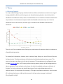
4.2.4 Stress Reduction Factor
Peysanj covers the following methods for calculating rd:
NCEER (1997)
rd= 1.0 - 0.00765 Z
for z ≤ 9.15 m
rd= 1.174 - 0.0267 Z
for 9.15 m < z ≤ 23 m
rd= 0.744 - 0.008 Z
for 23 m < z ≤ 30 m
39
PEYSANJ User's Manual (Novo Tech Software Ltd)
rd= 0.50
for z > 30 m
Thomas F. Blake (FugroWest Inc., Ventura, California)
Idriss & Boulanger (2006)
rd = 1 - 0.015 (Z - 4)
for z > 4 m
rd = 1
for z ≤ 4 m
Kayen et al. (1992)
rd = 1 - 0.012 Z
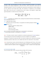
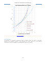
4.2.5 Cyclic Resistance Ratio (CRR)
4.2.5.1 SPT-based
All CRR7.5 calculation methods utilized in Peysanj are described below:
NCEER (1997) and Vancouver Task Force Report (2007)
These two methods are very similar expect that in "Vancouver Task Force Report (2007)" a K
parameter is multiplied in CRR7.5. In these methodologies, CRR7.5 is a function of depth corrected
SPT blow counts N1(60) for clean sand (fines content less than 5 percent). For sands containing
more fines content, more corrections will be applied on N1 (60). The CRR7.5 curve proposed by these
methodologies based on N1(60) is shown below:
40
PEYSANJ User's Manual (Novo Tech Software Ltd)
In NovoLiq, the equation proposed by Thomas F. Blake (Fugro West Inc., Ventura, California)
recommended by NCEER Workshop (1997) for clean sand curve, as shown below is used. This
equation is valid for N1(60)cs30
41
PEYSANJ User's Manual (Novo Tech Software Ltd)
Proposed CRR7.5 curve for clean sand (after Thomas F. Blake - NCEER Workshop)
The Kσ factor is calculated from the following formula:
Kσ = (σ΄vo / Pa)f-1
Where Pa is atmospheric pressure in the chosen units and f depends on relative density (Dr) and
given by:
f = 1 - 0.005 * Dr
for 40% < Dr < 80%
Dr ≤ 80% can be estimated using Dr = 100 * S(N1(60)/46)
Boulanger and Idriss (2004)
The following equation is proposed by Boulanger and Idriss (2004) for clean sand:
42
PEYSANJ User's Manual (Novo Tech Software Ltd)
Japanese Bridge Code
This methodology is based on SPT blow counts and particle size distribution of sand.
Where:
D50 : particle size corresponding to 50 percent passing
Fc : percent fines content passing sieve #200 (clay and silt)
Cetin et al, 2004
A complete explanation of this method is resented in the following paper:
Standard Penetration Test-Based Probabilistic and Deterministic Assessment of Seismic
Soil Liquefaction Potential
K. Onder Cetin, M.ASCE; Raymond B. Seed, M.ASCE; Armen Der Kiureghian, M.ASCE;
Kohji Tokimatsu; Leslie F. Harder Jr., M.ASCE; Robert E. Kayen, M.ASCE ; and Robert E.
S. Moss, M.ASCE
Note: Recently there has been technical discussions (by Dr Boulanger and Dr Idriss, 2010) about
the accuracy and reliability of Cetin et al (2004) method. Therefore it is recommended that this
method is used with cautious and full understanding of its risks. To obtain the full report please
contact us.
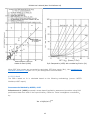
Other Methods
Some other CRR1 curves proposed by geoscientists are also implemented in NovoLiq. These
curves are shown in the following graph; Horizontal axis is normalized corrected SPT blow counts
(N1=0.833N1(60)).
43
PEYSANJ User's Manual (Novo Tech Software Ltd)
© Novo Tech Software All Rights Reserved
4.2.5.2 BDT-based
The approach for liquefaction assessment based on Becker Density Test (BDT) is essentially
assessing the liquefaction potential, using equivalent SPT blow counts (N 60). Two following
methods are covered in Peysanj for correlating Becker blows to SPT blows:
44
PEYSANJ User's Manual (Novo Tech Software Ltd)
Harder & Seed (1986)
Sy & Campanella (1993) with considering friction (RS)
When BDT blow counts are converted to equivalent SPT blow counts (N60), the procedures for
Standard Penetration Test(See 4.2.5.1) will be applied to field test data.
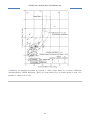
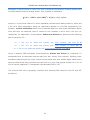
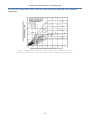
4.2.5.3 Vs-based
The CRR7.5 based on VS is calculated based on the following methodology (source: NCEER
Workshop 1997 report):
Recommended Method by NCEER, 1997
Robertson et al. (1992) proposed a stress-based liquefaction assessment procedure using field
performance data from sites in the Imperial Valley, California. These investigators normalized V S
by:
VS1 = VS(Pa/σ′vo)0.25
45
PEYSANJ User's Manual (Novo Tech Software Ltd)
where Pa is a reference stress of 100 kPa, approximately atmospheric pressure, and σ′vo is
effective overburden pressure in kPa. Robertson et al., 1992 suggested the liquefaction
resistance bound (CRR curve) for magnitude 7.5 earthquakes, plotted in the following figure along
with several sites where liquefaction did or did not occur. Subsequent liquefaction resistance
boundaries proposed by Kayen et al., 1992 and Lodge, 1994 for magnitude 7 earthquake are
also shown.
Figure 1 : Proposed cyclic stress ratio based on shear wave velocity.
The relationship proposed by Lodge (1994) provides a conservative lower boundary for
liquefaction case histories with VS1 less than about 200 m/s. The relationship by Robertson et al.
(1992) is the least conservative of the three. Professor Ricardo Dobry suggested a relationship
between cyclic resistance ratio and VS1 for constant average cyclic shear strain; This formula
supports a CRR bound passing through the origin and provides a rational approach for
extrapolating beyond the limits of the available field performance data, at least for lower values of
VS1 (VS1 ≤ 125 m/s).
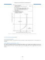
For higher values of VS1 , Andrus and Stokoe reason that the CRR bound should become
46
PEYSANJ User's Manual (Novo Tech Software Ltd)
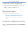
asymptotic to some limiting VS1 value. This limit is caused by the tendency of dense granular soils
to exhibit dilative behavior at large strains. Thus, equation is modified to:
av/σ′vo = CRR = a(VS1/100)2 + b/(VS1c - VS1) - b/VS1c
where VS1c is the critical value of VS1 which separates contractive and dilative behavior, and a and
b are curve fitting parameters. Using the relationship between VS1 and CRR expressed by this
equation , Andrus and Stokoe drew curves to separate data from sites where liquefaction effects
were and were not observed. Best fit values for the constants a and b were 0.03 and 0.9,
respectively, for magnitude 7.5 earthquakes. Andrus and Stokoe also determined the following
best-fit values for VS1c :
VS1c
=
VS1c =
220
m/s
for
sands and
gravels
with
210 m/s for sands and gravels with
fines
contents
less
fines contents of
than
about
5
%
20 %
VS1c = 200 m/s for sands and gravels with fines contents greater than 35 %
Figure 2 presents CRR boundaries recommended by Andrus and Stokoe for magnitude 7.5
earthquakes and un-cemented Holocene-age soils with various fines contents. Although these
boundaries pass through the origin, natural alluvial sandy soils with shallow water tables rarely
have corrected shear wave velocities less than 100 m/s, even near ground surface. For a V S1 of
100 m/s and a magnitude 7.5 earthquake, the calculated CRR is 0.03
This minimal CRR value is generally consistent with intercept CRR values for the CPT and SPT
procedures.
47
PEYSANJ User's Manual (Novo Tech Software Ltd)
Figure 2 : Proposed cyclic stress ratio curves for different fines content (FC).
4.2.6 Post Liquefaction Movements
4.2.6.1 Lateral Spreading
The following method of estimating the post-liquefaction lateral displacements is incorporated into
Peysanj:
Zhang, Robertson and Brachman, 2004
This method is essentially based on estimating maximum cyclic shear strain of each layer during
and after liquefaction which is estimated from safety factor against soil liquefaction (FS) and
relative density of soil (Dr), when Dr itself can be correlated from SPT or equivalent SPT blow
counts.
48
PEYSANJ User's Manual (Novo Tech Software Ltd)
Figure 1 : maximum cyclic shear strain for post liquefaction
lateral displacement proposed by Zhang, Robertson and Brachman, 2004.
Then, the Lateral Displacement Index (LDI) is calculated from the following equation:
and according to site sloping conditions (Gently Sloped / Free Face) the lateral displacement is
estimated. To read the complete procedure proposed by the authors, please read the following
paper from our website:
Estimating Liquefaction-Induced Lateral Displacements Using the Standard Penetration
Test or Cone Penetration Test
G. Zhang; P. K. Robertson; and R. W. I. Brachman
4.2.6.2 Reconsolidation Settlement
Post-liquefaction settlements occur during and after earthquake shaking. For level ground
conditions the amount can be computed from the volumetric reconsolidation strains induced as
the excess pore water pressures dissipate. Based on field experience during past earthquakes, the
amount of volumetric strain depends on penetration resistance and the CSR applied by the design
earthquake. Curves proposed by Ishihara and Yoshimine (1992) are shown in Figure 1 and
indicate that volumetric reconsolidation strains can range between about 4.5% for very loose sand
49
PEYSANJ User's Manual (Novo Tech Software Ltd)
to 1% for very dense sands. These curves are recommended for estimating post-liquefaction
settlements.
Figure 1 : Recommended relationships for volumetric reconsolidation strains as a
function of maximum shear strain and relative density (Ishihara & Yoshimine 1992)
50
PEYSANJ User's Manual (Novo Tech Software Ltd)
5. Online Resources
5.1 Novo Tech Website
http://www.novotechsoftware.com
5.2 PEYSANJ Updates
http://www.novotechsoftware.com/updatelogs/peysanj.txt
5.3 Other Programs
http://www.novotechsoftware.com/products/
5.4 Contact Us
http://www.novotechsoftware.com/contact-us/
51