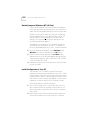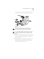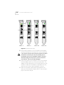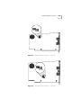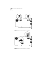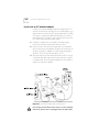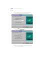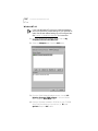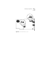
1
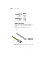
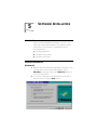
Sportster ISDN 128K
Terminal Adapter
Installation Guide
Version 5.4
http://www.3com.com/
Part No. 1.024.0477-02
Published May 1998
3Com Corporation
n
5400 Bayfront Plaza
n
Santa Clara, California
n
95052-8145
Copyright © 1998, 3Com Corporation. All rights reserved. No part of this documentation may be
reproduced in any form or by any means or used to make any derivative work (such as translation,
transformation, or adaptation) without written permission from 3Com Corporation.
3Com Corporation reserves the right to revise this documentation and to make changes in content
from time to time without obligation on the part of 3Com Corporation to provide notification of such
revision or change.
3Com Corporation provides this documentation without warranty of any kind, either implied or
expressed, including, but not limited to, the implied warranties of merchantability and fitness for a
particular purpose. 3Com may make improvements or changes in the product(s) and/or the program(s)
described in this documentation at any time.
UNITED STATES GOVERNMENT LEGENDS:
If you are a United States government agency, then this documentation and the software described
herein are provided to you subject to the following:
United States Government Legend: All technical data and computer software is commercial in nature
and developed solely at private expense. Software is delivered as Commercial Computer Software as
defined in DFARS 252.227-7014 (June 1995) or as a commercial item as defined in FAR 2.101(a) and as
such is provided with only such rights as are provided in 3Com’s standard commercial license for the
Software. Technical data is provided with limited rights only as provided in DFAR 252.227-7015 (Nov 1995)
or FAR 52.227-14 (June 1987), whichever is applicable. You agree not to remove or deface any portion of
any legend provided on any licensed program or documentation contained in, or delivered to you in
conjunction with, this Installation Guide.
[Portions of this documentation are reproduced in whole or in part with permission from (as
appropriate).]
Unless otherwise indicated, 3Com registered trademarks are registered in the United States and may or
may not be registered in other countries.
3Com, the 3Com logo, Sportster, Boundary Routing, EtherDisk, EtherLink, EtherLink II, LANplex,
LinkBuilder, Net Age, NETBuilder, NETBuilder II, OfficeConnect, Parallel Tasking, SmartAgent,
SuperStack, TokenDisk, TokenLink, Transcend, and ViewBuilder are registered trademarks of
3Com Corporation. ATMLink, AutoLink, CoreBuilder, DynamicAccess, FDDILink, FMS, NetProbe, and
PACE are trademarks of 3Com Corporation. 3ComFacts is a service mark of 3Com Corporation.
Artisoft and LANtastic are registered trademarks of Artisoft, Inc. Banyan and VINES are registered
trademarks of Banyan Systems Incorporated. CompuServe is a registered trademark of
CompuServe, Inc. DEC and PATHWORKS are registered trademarks of Digital Equipment Corporation.
Intel and Pentium are registered trademarks of Intel Corporation. AIX, AT, IBM, NetView, and OS/2 are
registered trademarks and Warp is a trademark of International Business Machines Corporation.
Microsoft, MS-DOS, Windows, and Windows NT are registered trademarks of Microsoft Corporation.
Novell and NetWare are registered trademarks of Novell, Inc. PictureTel is a registered trademark of
PictureTel Corporation. UNIX is a registered trademark of X/Open Company, Ltd. in the United States
and other countries.
Other brand and product names may be registered trademarks or trademarks of their respective
holders.
ii
CONTENTS
ABOUT THIS GUIDE
Introduction 7
Finding Specific Information in This Guide
Conventions 8
Additional Information 8
Year 2000 Compliance
9
ISDN Resources on the Internet 10
7
1 OVERVIEW
Introduction 1-1
What Does the Sportster ISDN 128K TA Do?
Access to the Internet 1-1
Telecommuting 1-1
Peer-to-Peer Network Programs 1-1
Peripheral Devices 1-2
What is ISDN? 1-2
The ISDN Basic Rate Interface 1-3
1-1
2 ORDERING ISDN SERVICE
Introduction 2-1
Setting Up ISDN Service 2-1
Ordering ISDN 2-1
Requesting Service from the Telephone Company
2-1
3 INSTALLATION CHECKLIST
iii
Introduction 3-1
Installation Checklist 3-1
ALL USERS: Required Items 3-1
ALL USERS: Optional Items 3-1
INTERNET ACCESS ONLY 3-2
USERS: Required Items 3-2
For Windows 95/98 configuration
For Windows NT 4.0 configuration
3-2
3-2
4 HARDWARE INSTALLATION
Introduction 4-1
Installation Overview 4-1
Hardset Jumpers (Windows NT 4.0 Only) 4-2
Install the Sportster in Your PC 4-2
Connect the ISDN Line 4-7
If you have a U Interface adapter 4-7
If you have an S/T Interface adapter 4-8
Connect a Phone (Optional)
4-9
If you have an analog phone 4-9
If you have an ISDN phone 4-10
Turn On Your PC 4-10
Install your Sportster software 4-10
5 SOFTWARE INSTALLATION
Introduction 5-1
Software Installation 5-1
Windows 95 5-1
Windows 98 5-3
Windows NT 4.0 5-4
Sportster Configuration 5-5
Windows 95/98 5-5
Windows NT 4.0 5-8
Sportster Online Help 5-10
A TECHNICAL SUPPORT
Introduction A-1
Online Technical Services A-1
Support from Your Network Supplier
iv
A-1
Support from 3Com A-2
Returning Products for Repair
A-2
B S/T ADAPTER TERMINATION SETTINGS
Introduction B-1
Terminating Multiple Devices B-1
Multiple Devices Less Than 100 Feet From the NT-1
Multiple Devices Less Than 700 Feet From the NT-1
Terminating a Single Device B-2
B-1
B-2
C TECHNICAL SPECIFICATIONS
Introduction C-1
General Specifications C-1
ISDN S/T Interface C-2
ISDN U Interface C-2
ISDN RJ-45 Connector C-2
ISDN RJ-11 Connector C-3
Analog Phone Interface C-4
PC Interface C-4
I/O Base Address Settings C-4
3COM CORPORATION LIMITED WARRANTY
FCC CLASS A VERIFICATION STATEMENT
FCC CLASS B STATEMENT
FCC DECLARATION OF CONFORMITY
3COM END USER SOFTWARE LICENSE AGREEMENT
INDEX
v
vi
ABOUT THIS GUIDE
Introduction
This manual provides step-by-step instructions for installing
and setting up the Sportster ISDN 128K terminal adapter
hardware and software to complete a call across the ISDN
network.
This guide is intended for beginning and advanced users of
ISDN products.
If the information in the release notes shipped with your
product differs from the information in this guide, follow
the instructions in the release notes.
Finding Specific Information in This Guide
This table shows the location of specific information in this
guide.
If you are looking for
Turn to
An introduction to the Sportster ISDN 128K TA
Chapter 1
Information about setting up ISDN Service
Chapter 2
A checklist to guide you through the installation process
Chapter 3
Instructions on how to install the Sportster hardware
Chapter 4
Instructions on how to install and configure the Sportster software
Chapter 5
Technical Support Information
Appendix A
S/T Adapter Termination Settings
Appendix B
Sportster Technical Specifications
Appendix C
8
ABOUT THIS GUIDE
Conventions
Table 1 Notice Icons
Icon
Notice Type
Description
Information note
Important features or instructions
Caution
Information to alert you to potential damage to a
program, system, or device
Warning
Information to alert you to potential personal injury
Additional Information
When using the unit, observe the following safety
information:
■
Retain this install guide for later use and pass it on to
subsequent owners/managers of the unit.
■
Protect the unit from sudden, transient increases and
decreases in electrical power by fitting an in-line surge
suppressor or uninterruptible power supply.
■
Products manufactured by 3Com are safe and without
risk provided they are installed, used, and maintained
in good working order and in accordance with their
instructions and recommendations.
■
Should any of the following conditions occur, isolate
the electricity supply and refer to your 3Com reseller.
■
■
■
If the unit begins to make an odd noise, smell or
smoke.
If the unit shows signs of a distinct change in
performance.
Never install telephone wires during a lightning storm,
or install telephone connection sockets in wet
locations (unless the socket is specifically designed for
wet locations).
Year 2000 Compliance
9
■
Do not touch uninstalled telephone wires or terminals
unless the telephone line has been disconnected at
the network interface. Always exercise caution when
installing or modifying telephone lines.
■
Do not use a telephone that is connected to the unit
to report a gas leak in the vicinity of the leak.
■
Do not use a telephone that is connected to the unit
(other than a cordless type) during an electrical storm.
There may be a remote risk of electric shock from
lightning.
■
Do not spill food or liquids on the unit. If the unit gets
wet, isolate the electrical supply and contact your
3Com reseller.
■
Do not push any objects into the openings of the unit.
Doing so can cause fire or electric shock by shorting
out internal components.
■
Ensure nothing rests on the unit’s system cables and
that the cables are not located where they can be
stepped on and cause damage to the unit.
■
Keep the unit away from radiators and heat sources.
Allow 25mm (1 inch) around the unit or stack to
provide adequate air circulation.
■
Install the unit in a clean area that is free from dust or
extreme temperatures.
■
The unit has been designed to be a free standing unit
or stacked with other units. Do not place anything
else on top of the unit’s case.
■
Allow a clearance gap of at least a 150 mm from the
rear panel of the unit, to allow for cable access.
Year 2000 Compliance
For information on Year 2000 compliance and 3Com
products, visit the 3Com Year 2000 web page:
http:// www.3com.com/products/usr_yr2000_stmnt.html
10
ABOUT THIS GUIDE
ISDN Resources on the Internet
■
■
■
Bellcore ISDN Home Page, on the World Wide Web:
http://www.bellcore.com/ISDN/ISDN.html
The frequently asked questions (FAQ) list from the
Internet newsgroup comp.dcom.isdn, available from
ftp://rtfm.mit.edu/pub/usenet/
Dan Kegel’s ISDN Page, on the World-Wide Web at
http://alumni.caltech.edu/~dank/isdn/
OVERVIEW
1
Introduction
This chapter is separated into the following sections:
■
■
What does the Sportster ISDN 128K TA Do?
What is ISDN?
What Does the Sportster ISDN 128K TA Do?
You can use the Sportster ISDN 128K terminal adapter (TA)
to connect your personal computer (PC) to a remote
computer network. The remote network can be the
Internet or, if you are a telecommuter, it can be your office
network.
Access to the Internet
If you are connecting to the Internet you will be able to use
all of the features offered by your Internet access program.
These features vary from program to program. They may
include browsing, uploading and downloading files, using
electronic mail, and accessing World Wide Web sites and
chat rooms.
Telecommuting
If you are telecommuting, you will use the office network
just as you would if you were at work. For example, if you
normally log into the office network for file retrieval and
storage, you will use the same procedure from your home
PC to open and save files. If you use electronic mail over a
local area network (LAN) at work, you will be able use the
same electronic mail program at your home.
Peer-to-Peer Network Programs
You can also use the adapter to connect to a single remote
PC that contains another Sportster.
1-2
CHAPTER 1: OVERVIEW
This allows you to use peer-to-peer network programs for
file sharing between two PCs.
Peripheral Devices
Additionally, you can attach a telephone, fax or modem to
the Sportster and use these devices at the same time that
you’re transferring data. To hear incoming calls on your
telephone handset and receive modem/fax calls, you
require an optional External Ring Generator.
What is ISDN?
The Sportster uses a special digital telephone line to
connect your computer with the remote network or PC.
These lines are called ISDN, or Integrated Services Digital
Network. ISDN is a service provided by your phone
company that lets you send digital information (the kind
you store in a computer) directly over the phone lines. You
can send more information and send it faster over an ISDN
line than you can over analog telephone lines.
The following diagram shows how your adapter can
connect to the Internet or to an office network. The
telephone company supplies the ISDN lines and the ISDN
network. You set up your PC software to call the ISDN
phone number assigned to the remote device or network
you wish to access.
Figure 1-1 Using the Sportster ISDN 128K Adapter
What is ISDN?
1-3
Digital technology makes it possible to combine
transmissions from a variety of devices into one network.
These devices include computers, telephones, and fax
machines.
Because ISDN was designed for transmitting digital
information, it has many advantages over the analog
telephone network. The benefits to you include more
accurate and reliable digital transmission, increased
transmission speeds (up to 64,000 bits per second (64
Kbps) per channel), and quicker call setups and teardowns.
The ISDN Basic Rate Interface
Physical Appearance
The Sportster communicates over a telephone line called an
ISDN Basic Rate Interface (BRI) line. You must order a BRI
line from your local telephone company before you can use
your Sportster. Chapter 2 explains how to order ISDN
service and which services to request.
BRI uses the same wires that are in place for your analog
telephone lines. The difference between ISDN lines and
regular telephone lines lies in the equipment that you
attach on each end of a line and in the type of electronic
signaling that these lines carry; there is no physical
difference between analog and ISDN telephone wires.
The BRI line uses an RJ-45 or RJ-11 wall jack. RJ-45
connectors have 8 pins and RJ-11s have 4 or 6 pins. You
can plug an ordinary RJ-11 connector, the kind used with
your regular analog telephone, into an RJ-45 jack, and the
Sportster adapter will work correctly. However, an RJ-45
connector will not fit in an RJ-11 jack.
At their end of the BRI, the telephone company adds an
electronic device called a line card, which adapts your line
for ISDN signaling.
1-4
CHAPTER 1: OVERVIEW
Figure 1-2 RJ-45 and RJ-11 Connectors and Jacks
B channels and D channels
Although Basic Rate Interface signals are transmitted over
an ordinary pair of wires, BRI typically contains three
channels:
■
One 16 Kbps D channel for setting up calls
■
Two 64- Kbps B channels for carrying data and/or voice
calls
Figure 1-3 ISDN BRI—Three Logical Channels over One Pair of Wires
Required Components
Signals from the BRI line must be translated into signals
that your computer can understand. A couple of devices
must be in place to perform the translation. Figure 1-4
What is ISDN?
1-5
depicts them as you would see them on your desktop; and
Table 1–1 describes them verbally.
Figure 1-4 Typical Installation of a U Interface Sportster 128K
Table 1-1 ISDN BRI Components in Figure 1-4
Component
Definition
TE2
Terminal Equipment 2. A device, such as your
computer, that does not have built-in ISDN capability.
A TE2 requires a Terminal Adapter (TA), such as the
Sportster, to communicate over the ISDN.
TA
Terminal Adapter. A device that translates between
non-ISDN signaling, such as the EIA-232 signaling
that occurs at your computer’s serial port, and the S/T
interface signaling that the NT-1 understands.
NT-1
Network Termination [Unit] -1. An NT-1 translates
between the short-distance signaling used at the S/T
interface and the longer-distance signaling used at
the U interface. An NT-1 also converts from the two
wires used for the phone line to the six or eight wires
needed for the S/T bus.
1-6
CHAPTER 1: OVERVIEW
ORDERING ISDN SERVICE
2
Introduction
Although efforts are being made to simplify ISDN ordering,
it can still be a complex process. This chapter should give
you and your local telephone company all the information
you need to set up your ISDN lines correctly.
Setting Up ISDN Service
Ordering ISDN
Here’s an overview of the ordering process:
1 Call your local telephone company to request an ISDN line.
Explain the Sportster’s requirements as described in this
chapter.
2 Your local telephone company will give you information
about your line and its settings.
3 Program the line’s settings into your Sportster.
Requesting Service from the Telephone Company
Call the ISDN unit of your local telephone company. Provide
them with the information presented in the next section,
What to Tell Your Telephone Company. Then ask them for
the information outlined in the section What to Ask Your
Telephone Company.
What to Tell Your Telephone Company
1 Request Bellcore Capability Package K or M or EZ-ISDN1.
a Capability Package K and EZ-ISDN1 include voice/data
calls on one B channel and data calls on the other B
channel. They also feature Caller ID, Additional Call
Offering (ACO), and Flexible Calling. However, the
Sportster will not support the Flexible Calling Option.If
you choose one of these packages, the phone number
2-2
CHAPTER 2: ORDERING ISDN SERVICE
supporting voice/data calls should be entered as the
second phone number when you configure the
Sportster (Chapter 5).
Additional Call Offering is useful if both your B channels
are busy and you wish to be notified of an incoming call.
Normally, the caller will get a busy signal if both B channels
are in use.
b Capability Package M includes voice/data calls on both B
channels and Caller ID. Choose this package if you do
not want the ACO option available with Capability
Package K.
2 If your telephone company doesn’t recognize Bellcore
capability packages, you can also ask for a service package
called Intel Blue, which has characteristics nearly identical
to Bellcore M. Either package will provide you with 128
Kbps transmission potential, which will enable you to take
full advantage of your Sportster’s Multi-link PPP (MLPPP)
support.
If your phone company recognizes neither of these service
packages, you should request the following specific ISDN
services and service characteristics:
■
■
■
■
■
■
■
■
■
■
■
■
■
ISDN BRI service
2 B channels
■
B1/B2: Circuit-switched voice/data (CSV/D) call types
Enable both B channels to work simultaneously
No packet mode (X.25) data on the B or D channels
No EKTS or CACH EKTS services
Terminal type A
Dynamic TEI assignments
Low and high-layer compatibility data transfer ON
Called and calling party subaddress information ON
Idle call appearance
No additional call appearances
Flexible calling features or buttons for voice, such as:
■
ACO
■
Caller ID
2B1Q line coding
Setting Up ISDN Service
■
2-3
RJ-45 (8 pin) or RJ-11 (4 or 6 pin) connector
3 Specify your preferred long-distance provider (i.e., AT&T).
What to Ask Your Telephone Company
Make sure your local telephone company provides you with
the following information.
1 Find out at which type of central office switch your ISDN
line will terminate, and which protocol will be controlling
your calls.
a Any switch running the National ISDN protocol (NI-1)
b AT&T 5ESS switch running AT&T’s Custom protocol
c Nortel DMS-100 switch running NT’s Custom protocol
If your telephone company’s switch detects power losses to
the on-board or external NT-1, it may generate an alarm.
(Older Nortel DMS-100 Custom switches may function in
this way.) When the alarm is generated, the switch may
temporarily disconnect your line.
2 How many phone numbers are assigned to your ISDN line?
Note that for AT&T 5ESS Custom switches there should be
only one number.
❑1❑2
3 What are the phone numbers? If the line is provisioned for
voice and data there may be a separate number for the B
channel that carries voice.
Primary data number ______________________________
Voice/secondary number (if used)____________________
Service Profile Identifiers (SPIDs) [if used]______________
2-4
CHAPTER 2: ORDERING ISDN SERVICE
INSTALLATION CHECKLIST
3
Introduction
The Installation Checklist tells you what things you need to
have before you can install, set up, and operate the
Sportster 128K TA. The installation instructions in the next
chapter assume that the Checklist has been completed, so
take the time to fill it out now. It will make the installation
and set up process go more smoothly and quickly.
Installation Checklist
ALL USERS: Required Items
■
PC - Intel486 or better
■
Sportster ISDN 128K U or S/T Interface TA
■
ISDN cable for Sportster
■
Sportster ISDN 128K Terminal Adapter Installation
Guide (this guide)
■
Release Notes
■
Installation and Setup CD-ROM
■
NT-1 (for S/T Interface adapter only)
■
Complete information from your telephone company
about your ISDN Service (see checklist in Chapter 2)
ALL USERS: Optional Items
■
Analog or ISDN (S/T only) Telephone
■
Telephony Software, such as a phone manager
■
External Ring Generator
3-2
CHAPTER 3: INSTALLATION CHECKLIST
INTERNET ACCESS ONLY
USERS: Required Items
■
An account with an Internet access provider, who
should tell you the following information:
__________________________ An ISDN phone number
__________________________ A user name
__________________________ A user password
Which connection protocol your provider supports:
❑ PPP ❑ MLPPP
For Windows 95/98 configuration
For WinISDN, you must have an Internet access application
software package, such as Explore OnNet or Chameleon,
that is compatible with WinISDN.
For Dial-Up Networking, you must have enabled Dial-Up
Networking when you set up Windows 95 or 98 and have
an Internet browser application such as Netscape Navigator
or Microsoft Internet Explorer.
If you are new to Windows Networking, you should review
your Windows online help topics before proceeding with
Installation. Some helpful topics are:
Installing a network protocol
Changing settings for a network protocol
Changing properties for a Dial-Up connection
Using Dial-Up Networking to connect to another computer
or network
Connecting to the Internet using Dial-Up Networking
For Windows NT 4.0 configuration
You must have an Internet access application software
package, Netscape Navigator, or Microsoft Explorer, that is
compatible with Remote Access Software
INTERNET ACCESS ONLY
3-3
3-4
CHAPTER 3: INSTALLATION CHECKLIST
Hardware Installation
4
Introduction
Now that your ISDN service has been ordered and installed
and you have completed the tasks in the Installation
checklist, you are ready to install your Sportster ISDN 128K
TA. This chapter guides you through the hardware
installation process. It is separated into the following
sections:
■
■
■
■
■
■
■
Installation Overview
Hardset Jumpers (Windows NT 4.0 Only)
Install the Sportster in your PC
Connect the ISDN Line
Connect a phone (optional)
Turn on your PC
Install your Sportster software
Installation Overview
Installing the Sportster is done in just four or five easy
tasks. Here’s the overview:
1 Hardset Jumpers (Windows NT 4.0 Only)
2 Install the Sportster in your PC
3 Connect the ISDN line
4 Connect a phone (optional)
5 Turn on your PC
6 Install your Sportster software
4-2
CHAPTER 4: HARDWARE INSTALLATION
Hardset Jumpers (Windows NT 4.0 Only)
If you have Windows NT, before you install the hardware
you must hard set the jumper settings on your Sportster to
match the I/O base address settings you will configure later.
Figures 4-3 through 4-6 show you how your jumpers are
positioned depending on your device (If you have an S/T
interface device, consult Appendix B: S/T Termination
Settings). You must match the jumper setting with the
corresponding I/O base address.
The address you configure for your Sportster should not
conflict with any other device on your PC. To determine
which I/O base address setting is “free,” follow these steps:
1 From the Windows NT desktop, select Start/Run. Type
Winmsd in the Open field and press the OK button.
2 Select the Resource tab and press the I/O Port button.
Determine which of the I/O base address settings are free.
The settings are listed in “pairs” (300/700 is 300, 320/720
is 320, and 340/740 is 340).
3 Hardset the jumpers to the free resource you will configure
for your Sportster.
Install the Sportster in Your PC
The Sportster is a U.L.-listed Information Technology
Equipment Accessory and is intended for use in a U.L.-listed
computer. Refer to your PC user’s guide to see that it meets
this specification, and for instructions specific to your brand
and model on how to install a new adapter. You will need a
screwdriver or wrench that fits your computer’s screws.
Follow these steps to install the Sportster:
1 Turn off and unplug the PC, then remove the cover. You
don’t need to disconnect anything but the power. If you
don’t know how to remove the cover, see your computer
user’s guide.
2 Remove the screw holding the metal bracket covering an
unused 16-bit expansion slot (see Figure 4-1), and then
Install the Sportster in Your PC
4-3
remove the bracket. You will not need the bracket to install
your Sportster. You will need the screw, so set it aside.
Figure 4-1 Expansion Slot
Don’t shock yourself. Unplug the computer and any
attached equipment before you install the adapter.
Don’t damage the adapter with static electricity. Ground
yourself by touching the computer’s metal back or side
panel.
3 Before removing the adapter from its antistatic bag, ground
yourself by touching the metal part of the computer’s case.
Then remove the adapter by grabbing the non-metallic
sides of the adapter.
4 Determine the type of Sportster you are installing. You can
easily determine the type of adapter by examining the
bracket style located on the end of the board. Figure 4-2
illustrates all possible Sportster types.
4-4
CHAPTER 4: HARDWARE INSTALLATION
NETWORK
LINE
NETWORK
NETWORK
NETWORK
ISDN S/T
ISDN S/T
PHONE
PHONE
LINE
ISDN U
ISDN U
NT-1 BACKUP POWER NT-1 BACKUP POWER
PHONE
TYPE 1 - U
PHONE
TYPE 2 - U
TYPE 1 - S/T
TYPE 2 - S/T
Figure 4-2 Sportster bracket types
5 Verify that the jumpers on your Sportster are terminated
correctly (See Figures 4-3 through 4-6 for factory defaults).
If you remove the shunt that covers the jumpers be careful
to replace it so that the pins from one jumper are not
connected to the pins of an adjacent jumper. The shunt
should slip easily onto the pins. Do not force the shunt
onto the pins. They can be easily damaged.
6 Insert the Sportster into the expansion slot in the computer.
Hold the adapter at the top corners and push down. The
adapter should slide easily most of the way. When you feel
resistance, make sure the adapter is aligned with the slot,
and then push firmly to seat the adapter in the slot.
7 Fasten the Sportster’s metal retaining bracket with the
screw you removed earlier. Replace the PC cover, but don’t
plug in the power cord yet.
Install the Sportster in Your PC
-3 -3
3 3
- -
Figure 4-3 Jumper locations for the Type 1 - U Interface
-3 -3
3 - -3
Figure 4-4 Jumper locations for the Type 2 - U Interface
4-5
4-6
CHAPTER 4: HARDWARE INSTALLATION
-3
-3 -3
-3
Figure 4-5 Jumper locations for the Type 1 - S/T Interface
-
-
-3
-3
Figure 4-6 Jumper locations for the Type 2 - S/T Interface
Connect the ISDN Line
4-7
Connect the ISDN Line
How you connect the Sportster to the ISDN line depends
on whether you have a U interface or S/T interface adapter.
If you are unsure which type you have, look at the bracket.
If there are two LEDs and a center power supply port, it is a
U interface board. If it has one LED and there is no center
power supply port, it is an S/T interface board.
If you have a U Interface adapter
1 Plug one end of the cable that came with your Sportster
into the top jack on the adapter and plug the other end
into the ISDN wall jack.
2 (Optional) Install the NT-1 Backup Kit. The Kit provides
power to the NT-1 when your computer is off. You may
wish to install this piece of equipment if your telephone
company’s switch detects the loss of power to the NT-1
and then generates an alarm. Instructions for installing this
backup power supply are included with the Kit.
The NT-1 Backup Kit will NOT allow you to receive or place
phone calls with the analog device port when your PC is
powered OFF.
Figure 4-7 U Interface Adapter with onboard NT-1
4-8
CHAPTER 4: HARDWARE INSTALLATION
If you have an S/T Interface adapter
Usually, S/T interface adapters require an external NT-1. If
you are connecting to an ISDN line from a PBX system, you
may be able to connect the S/T interface directly to the PBX
connection. Contact your PBX administrator to find out if
you need an NT-1. The NT-1 may consist of two pieces: The
NT-1 itself and a separate power supply.
1 If the NT-1 needs to be connected to a power supply,
follow the instructions that came with your NT-1.
2 Plug one end of the cable that came with your Sportster
into the top jack on the adapter. Plug the other end into an
S/T jack on the NT-1 adapter. This jack might be labeled
Terminal, TE (for Terminal Equipment), or S/T.
3 Plug one end of the cable that came with the NT-1 into the
U interface wall jack and plug the other end into the NT-1
U interface jack, which might be labeled Line. See the NT-1
instruction manual for details.
Figure 4-8 S/T Interface Adapter with an external NT-1
Don’t shock yourself. Be sure the cover is on the computer
and the PC power cord is unplugged from the wall outlet.
Connect a Phone (Optional)
4-9
4 The S/T termination on the NT-1 should be set to 100
ohms. (See your NT-1 documentation for setting
termination.) The Sportster S/T adapter termination was set
to 100 ohm at the factory. If you need to change these
default settings, refer to Tables B-1 through B-3 in
Appendix B: S/T Adapter Termination Settings.
Connect a Phone (Optional)
If your telephone company has provided you with two B
channels, one of which is provisioned for both voice and
data calls, you may wish to attach a voice telephone to the
Sportster. You may use either a standard analog phone (a
touch-tone phone that uses tones, not pulses) or, with the
S/T interface model only, an ISDN phone.
If you have an analog phone
If you have a standard analog phone, connect it to the
Sportster (S/T or U interface versions) using a standard
phone cable with a standard connector. Plug the connector
into the bottom jack on the Sportster.
There are two differences between the Sportster’s
connection and a regular analog phone connection:
1 External Ringing on an analog telephone handset: To
enable the External Ringing Option, you require an External
Ring Generator. This device is listed in the Optional
Products List for the Sportster that was included in the
product box. The External Ring Generator will allow your
telephone handset to ring when you receive a voice call. It
will also allow a modem or fax machine attached to your
PC to auto answer data calls. If you do not have the
External Ringing Option selected, you can set a Voice
Ringing Pattern to allow your Sportster to ring when you
receive a voice call.
2 The phone will not operate when the PC is turned off or
the Sportster software is not running.
4-10
CHAPTER 4: HARDWARE INSTALLATION
If you have an ISDN phone
If you want to use an ISDN phone, you need a Sportster
with an S/T interface. Most external NT-1s provide two S/T
terminal RJ-45 jacks. Plug the Sportster into one of these
jacks and the ISDN phone into the other jack. The NT-1
should be connected to the ISDN wall jack (U interface)
installed by the telephone company.
Unlike the standard analog phone, the ISDN phone will
work when your PC is turned off and the Sportster
software is not running. For more information on
connecting and using your ISDN phone, see the
documentation that came with the phone.
Turn On Your PC
Reconnect your PC’s power cord, and turn on the power.
Install your Sportster software
Now you are ready to install the Sportster software that
matches your operating system (Windows 95, 98, or NT
4.0). Proceed to the next chapter for instructions on
Sportster software installation.
SOFTWARE INSTALLATION
5
Introduction
After you have installed your Sportster in your PC, you
must load the Sportster software. This chapter provides
instructions on this process. It is separated into the
following sections:
■
■
■
Software Installation
Sportster Configuration
Sportster Online Help
Software Installation
Windows 95
1 Place the Sportster ISDN 128K Installation CD-ROM in your
CD-ROM drive. From the Windows desktop, select
Start/Run. In the Open field, enter Setup.exe and point
to your CD-ROM drive.
2 You will be introduced to the Installation process with a
welcome screen. Press the Next button.
5-2
CHAPTER 5: SOFTWARE INSTALLATION
3 The Installation directory tab will display the system
directory where the software will be installed.
4 Press the Next button to proceed. From the Summary
screen, press the Start Copy button.
5 After the Sportster software has finished installing, you
must configure the adapter.
Software Installation
5-3
Windows 98
If you are a Windows 95 user upgrading to Windows 98
and have Sportster software installed already, you must
re-install the software. If you have an earlier version of the
software (5.3 or below), you will NOT be able to install it on
Windows 98. Visit the 3Com website
(http://www.3com.com) to obtain the latest software.
To uninstall the software, double click My Computer/
Control Panel from the Windows desktop. Select
Add/Remove Programs and choose the Sportster from
the scroll down list. Press the Add/Remove button.
If you have previously installed the Sportster from the
Microsoft Windows 98 CD-ROM, it is highly recommended
that you un-install that software and re-install the software
from the Sportster ISDN 128K Installation CD-ROM.
To uninstall the software, from the Windows desktop,
select My Computer/Control Panel. Double click on the
Network icon and select the Configuration tab. Highlight
the Sportster and press the Remove button.
To install the Sportster software, follow these steps:
1 Enter the Sportster Installation CD-ROM in your CD-ROM
drive.
2 From the Windows desktop, select Start/Run. In the Open
field, enter the directory of your CD-ROM drive (i.e., D:\)
and enter Setup.exe and point to your CD-ROM drive.
3 In the Welcome screen, press the Next button. The
Installation directory screen will display C:\Program
Files\Sportster ISDN 128K, the location where the
software will be installed. Press the Next button.
4 In the summary window, press the Start Copy button.
5 After the Sportster software has finished installing, you
must configure the adapter.
5-4
CHAPTER 5: SOFTWARE INSTALLATION
Windows NT 4.0
If you have Windows NT, before you install the hardware
you must hard set the jumper settings on your Sportster to
match the I/O base address settings you will configure later.
See Chapter 4: Hardware Installation for instructions.
1 From the Windows NT desktop, double click on My
Computer/Control Panel/Network.
2 Select the Adapters tab. Press the Add button.
3 From the Select Network Adapter screen, choose U.S.
Robotics Sportster ISDN Adapter in the scroll down
menu. Press the Have Disk button.
4 Place the Sportster Installation CD-ROM in your CD-ROM
drive. Enter the directory of your drive (i.e., D:\) and
spwinnt. Press the OK button.
Sportster Configuration
5-5
5 After the Sportster software has finished installing, you
must configure the adapter.
Sportster Configuration
Windows 95/98
The ISDN settings entered initially through the Microsoft
ISDN configuration wizard will be used. If you wish to
modify these settings, you must use the Configuration
Settings button in your Sportster Manager.
1 Install the Sportster software. You will be prompted to
configure the adapter.
2 In the Resources window, you will see the Interrupt (IRQ)
and I/O base address range. Select settings which do not
conflict with your system configuration (i.e., used by other
devices). Press the OK and then the Next button.
5-6
CHAPTER 5: SOFTWARE INSTALLATION
3 Choose Automatic to have your Switch type and SPID(s)
detected for you and press the Next button. Enter the
phone number(s) with area code(s). Press the Next button.
4 If you know your Switch type, select it and press the Next
button. Enter the phone number(s) and SPID(s), if provided.
Press the Next button.
Sportster Configuration
5-7
5 To complete the ISDN configuration press the Finish
button. You should press the Restart Windows button to
complete the configuration.
6 Your Sportster will connect when you boot up Windows.
You should see the Startup Dialog.
5-8
CHAPTER 5: SOFTWARE INSTALLATION
Windows NT 4.0
1 Install the Sportster software. You will be prompted to
configure the adapter.
2 In the Adapter Board window are the I/O base address
range and the IRQ, which should not conflict with your
system configuration. Select the Voice Options (i.e., EXT)
and enable or disable Data Over Voice.
3 Under Adapter Information (read only), note the current
configuration status of the ISDN adapter.
4 Press the OK button and proceed to the Telephone
company screen. Under Telco Switch Information, enable or
disable Auto detect Switch type and SPID(s). If you choose
to disable the function, you must choose a Switch Type
from the scroll down menu provided.
Sportster Configuration
5-9
5 Enter a phone number and SPID (optional) in the 1st line
field. If you have another line, enter the information in the
2nd line field. Press the OK button.
To search for free resources, press the WinMSD button in
the configuration screen. To change the resource settings,
double click My Computer/Network and select
Adapters. Highlight the Sportster ISDN 128K and press the
Properties button.
6 Consult the Sportster online help for specific information.
You will be prompted to configure Remote Access Service
(RAS).
5-10
CHAPTER 5: SOFTWARE INSTALLATION
Sportster Online Help
For information on advanced configuration,
troubleshooting, and Sportster operation, consult the
Sportster online help. To access the help, under the tool bar
of the Sportster Manager (Windows 95/98) or the Line
Monitor (NT 4.0), select Help. To view the help:
1 Place the Sportster installation CD-ROM in your CD-ROM
drive. Select Start/Run.
2 In the Open field, enter the drive letter of your CD-ROM
(i.e., D:\) and spwin9x/managenu.hlp (Windows 95/98)
or spwinnt/managenu.hlp (Windows NT 4.0).
TECHNICAL SUPPORT
A
Introduction
3Com provides easy access to technical support
information through a variety of services. This appendix
describes these services. Information contained in this
appendix is correct at time of publication. For the very
latest, we recommend that you access 3Com Corporation’s
World Wide Web site.
This appendix is separated into the following sections:
■
■
■
■
Online Technical Services
Support from your Network Supplier
Support from 3Com
Returning Products for Repair
Online Technical Services
Access the latest networking information on 3Com
Corporation’s World Wide Web site by entering our URL
into your Internet browser:
http://www.3com.com/
This service features the latest information about 3Com
solutions and technologies, customer service and support,
news about the company, Net Age® Magazine, technical
documentation, and more.
Support from Your Network Supplier
If additional assistance is required, contact your network
supplier. Many suppliers are authorized 3Com service
partners who are qualified to provide a variety of services,
including network planning, installation, hardware
maintenance, application training, and support services.
A-2
APPENDIX A: TECHNICAL SUPPORT
When you contact your network supplier for assistance,
have the following information ready:
■
A list of system hardware and software, including
revision levels
■
Diagnostic error messages
■
Details about recent configuration changes, if applicable
If you are unable to contact your network supplier, see the
following section on how to contact 3Com.
Support from 3Com
If you are unable to receive support from your network
supplier, technical support contracts are available from 3Com.
Contact your local 3Com sales office to find your
authorized service provider using the following number:
(847) 797-6600
Returning Products for Repair
Before you send a product directly to 3Com for repair, you
must first obtain a Service Repair Order (SRO) number and
shipping address from Technical Support. Products sent to
3Com without SRO numbers will be returned to the sender
unopened, at the sender’s expense. Make sure you include
the following:
■
■
■
Your Name, Address, Telephone Number, and Company
Product Serial Number and Part Number (Located on
box)
Brief Description of Problem
S/T ADAPTER TERMINATION
SETTINGS
B
Introduction
An S/T interface is used in conjunction with an NT-1 when
more than one ISDN device is to be connected to the U
interface (your ISDN wall jack). A Sportster S/T connects to
the ISDN S/T bus. Buses always have two endpoints and, in
the case of the S/T bus, one end is typically at the NT-1 and
the other is where your last ISDN device connects. The NT-1
connects to the U interface. The S/T bus must be
terminated properly. To terminate the S/T bus, you typically
add a resistor in two places: at the NT-1 and at the end of
the S/T bus. The termination procedures differ depending
on the distance between the devised attached to the S/T
bus and the NT-1.
This appendix contains information about termination
settings of the Sportster S/T interface. It is separated into
the following sections:
■
■
Terminating Multiple Devices
Terminating a Single Device
Terminating Multiple Devices
There are two options for terminating multiple devices. Go
to the appropriate section for
your installation:
■
■
Multiple Devices Less Than 100 Feet From the NT-1
Multiple Devices Less Than 700 Feet From the NT-1
Multiple Devices Less Than 100 Feet From the NT-1
If all of the devices attached to the S/T bus are within 100
feet of the NT-1, set 50 ohms termination at the NT-1 and
remove the shunts from the pins to set no termination at
each device attached to the S/T bus. Since 100 ohms is the
B-2
APPENDIX B: S/T ADAPTER TERMINATION SETTINGS
default setting for the Sportster, you will need to change
the setting.
Figure B-1 Resistor Settings: All Devices (TEs) Less Than 100 ft. from
the NT-1
Multiple Devices Less Than 700 Feet From the NT-1
If you are placing a cluster of devices less than 700 feet
from the NT-1, set 100 ohms termination at the NT-1 and
100 ohms termination just before the branching point.
Wiring blocks with built-in 100 ohm termination exist.
Remove the shunts from the pins to set no termination on
each device attached to the S/T bus.
Figure B-2 Resistor Settings: All Devices (TEs) Clustered
Terminating a Single Device
If your S/T adapter is the only device connected to the NT-1,
the termination setting options are shown in Table B-1.
Table B-1 lists three possible options for setting the
termination of your external NT-1 and S/T adapter. Options
1 and 2 are only available on Type 2 S/T adapters. Option 3,
Terminating a Single Device
B-3
which is the preferred default setting, is available on both
Type 1 and Type 2 S/T adapters.
If you remove the shunt that covers the jumpers be careful
to replace it so that the pins from one jumper are not
connected to the pins of an adjacent jumper. Also the
shunt should slip easily onto the pins. Do not force the
shunt onto the pins. They can be easily damaged.
Table B-1 Termination Settings for an external NT-1 connecting only an S/T
Interface
S/T Type
Options
Device
Termination
Type 2
1
external NT-1
not terminated 50 ohms
Type 2
2
external NT-1
not terminated 50 ohms
Type 1 or 2
3
external NT-1
100 ohms
Preferred default
setting
100 ohms
Table B-1 describes the shunt settings to use for the
termination of the S/T Type 1 adapter. Pin layouts that
accompany this table are shown in Figure B-3. The default
setting is 100 ohms. For the S/T Type 1, termination at 50
ohms is not supported.
Table B-2 Jumper Settings for S/T Interface: Type 1
Termination
Jumper Settings
JP1
JP2
JP4
JP5
Not terminated
OUT
OUT
OUT
OUT
100 Ohms
IN
IN
IN
IN
50 Ohms
IN
OUT
IN
OUT
B-4
APPENDIX B: S/T ADAPTER TERMINATION SETTINGS
SLQ
SLQ
SLQ
-3 -3
-3 -3
SLQ
Figure B-3 Pin layouts for Sportster S/T - Type 1
Table B-3 describes the shunt settings to use for the
termination of the S/T Type 2 adapter. Pin layouts that
accompany this table are shown in Figure B-4. The default
setting is 100 ohms. Termination at 50 ohms is fully
supported using the settings in Table B-3.
Table B-3 Jumper Settings for S/T Interface: Type 2
Termination
Jumper
Settings
JP2
JP1
JP7
JP8
Not terminated
OUT
OUT
OUT
OUT
100 Ohms
IN
IN
IN
IN
50 Ohms
IN
OUT
IN
OUT
Terminating a Single Device
-
-
SLQSLQSLQ
-3
-3
SLQ
SLQ
Figure B-4 Pin Layouts Sportster S/T - Type 2
B-5
B-6
APPENDIX B: S/T ADAPTER TERMINATION SETTINGS
TECHNICAL SPECIFICATIONS
C
Introduction
This appendix lists the specifications for the Sportster. It is
separated into the following sections:
■
■
■
■
■
■
■
■
General Specifications
ISDN S/T Interface
ISDN U Interface
ISDN RJ-45 Connector
ISDN RJ-11 Connector
Analog Phone Interface
PC Interface
I/O Base Address Settings
General Specifications
Characteristic
Specification
Power
+5Vdc 1.6 watts nominal, 1.9 watts
maximum
+12Vdc 0.8 watts maximum
-12Vdc 0.8 watts maximum
Temperature
Storage: -40C to +70C
Operating: 0C to +55C
Humidity
Non-operating: RH of 92% @ +55C
Operating: RH of 85% @ +55C
MTBF*
320,000 hours @ 20C
*Mean time between failures
C-2
APPENDIX C: TECHNICAL SPECIFICATIONS
ISDN S/T Interface
Characteristic
Specification
Switch Compatibility
Compatible with AT&T 5E4.2, 5E5 through 5E9 software
generics
Compatible with Nortel DMS-100’s Functional software
generics BCS 29 through BCS 36
Complies with National ISDN (NI1) SR-NWT-001953
S/T Interface
Complies with ANSI T1.605 - 1991 Basic Rate Interface
specifications
Complies with Bellcore’s National ISDN specifications
SR-NWT-001953
S/T Termination
User-selectable: None (bridges), 100 ohms ± 5% or 50
ohms ± 5%. Factory default = 100 ohms
ISDN U Interface
Characteristic
Specification
Switch Compatibility
Compatible with AT&T 5E4.2, 5E5 through 5E9 software
generics
Compatible with Nortel DMS-100’s Functional software
generics BCS 29 through BCS 36
Complies with National ISDN (NI1) SR-NWT-001953
U Interface
Complies with ANSI T1.601 - ISDN Basic Access Interface
for use on metallic loops for application on the network
side of the NT (Layer 1 Specification - 1992)
Complies with Bellcore’s National ISDN specifications
SR-NWT-001953
ISDN RJ-45 Connector
The Sportster has one RJ-45 jack for the ISDN network
interface.The ISDN RJ-45 connector that you plug in to the
RJ-45 jack is either a U interface (two-wire) or a S/T
interface (four-wire), depending on which version of the
adapter you have purchased. The following table lists the
pin (pole) numbers and their corresponding signal name(s)
ISDN RJ-11 Connector
C-3
for the 8-position/8-pin modular RJ-45 connector only on
the U interface.
Pin Number
Signal
4
Ring
5
Tip
The following table lists the pin (pole) numbers and their
corresponding signal name(s) for the 8-position/8-pin
modular RJ-45 connector only on the S/T interface.
Pin Number
Signal
3
Transmit +
4
Receive +
5
Receive -
6
Transmit -
ISDN RJ-11 Connector
The following table lists the PIN (pole) numbers and their
corresponding signal name(s) for the Adapters single 6
position / 4-pin modular RJ-11 connector used for external
analog device connection (i.e., modem, phone, fax).
Positions 1 - 6 are not loaded (no pin) and positions 2 and 5
are loaded but unused.
Pin Number
Signal
3
Ring
4
Tip
C-4
APPENDIX C: TECHNICAL SPECIFICATIONS
Analog Phone Interface
Characteristic
Specification
AC impedance
600 ohms, + or - 20%
DC source resistance
600 ohms. + or - 5%
Loop current
35mA maximum
Loop voltage
25Vdc maximum
PC Interface
Characteristic
Specification
Bus Interface to Computer
One is a 16-bit interface (slot)
I/O Accesses
8-bit and 16-bit operation
I/O base address
requirements
Software selectable in Windows 95 and 98. One of
16 I/O base addresses, each being 16 consecutive
bytes in length, between 0x200 and 0x3E0 inclusive.
Jumper settings must be match software settings in
Windows NT 4.0.
Interrupt requirements
Software selectable. Can be any available IRQ: 5, 9,
10, 11, 12, or 15.
DMA requirements
none
Shared memory
requirements
none
I/O Base Address Settings
Jumper
Settings
I/O Base address
JP1
JP2
IN
IN
300
IN
OUT
320
OUT
IN
340
OUT
OUT
Default setting, software selectable. Not
available for Windows NT 4.0.
3Com Corporation LIMITED WARRANTY
HARDWARE
3Com warrants its hardware products to be free from defects in workmanship and materials, under
normal use and service, for the following lengths of time from the date of purchase from 3Com or its
Authorized Reseller:
Sportster ISDN 128K Terminal Adapter
1 year
Spare parts and spares kits
90 days
If a product does not operate as warranted above during the applicable warranty period, 3Com shall,
at its option and expense, repair the defective product or part, deliver to Customer an equivalent
product or part to replace the defective item, or refund to Customer the purchase price paid for the
defective product. All products that are replaced will become the property of 3Com. Replacement
products may be new or reconditioned. Any replaced or repaired product or part has a ninety (90) day
warranty or the remainder of the initial warranty period, whichever is longer.
3Com shall not be responsible for any software, firmware, information, or memory data of Customer
contained in, stored on, or integrated with any products returned to 3Com for repair, whether under
warranty or not.
SOFTWARE
3Com warrants that the software programs licensed from it will perform in substantial conformance to
the program specifications therefor for a period of ninety (90) days from the date of purchase from
3Com or its Authorized Reseller. 3Com warrants the media containing software against failure during
the warranty period. No updates are provided. The sole obligation of 3Com with respect to this express
warranty shall be (at the discretion of 3Com) to refund the purchase price paid by Customer for any
defective software products, or to replace any defective media with software which substantially
conforms to applicable 3Com published specifications. Customer assumes responsibility for the
selection of the appropriate applications program and associated reference materials. 3Com makes no
warranty or representation that its software products will work in combination with any hardware or
applications software products provided by third parties, that the operation of the software products
will be uninterrupted or error free, or that all defects in the software products will be corrected. For any
third-party products listed in the 3Com software product documentation or specifications as being
compatible, 3Com will make reasonable efforts to provide compatibility, except where the
noncompatibility is caused by a “bug” or defect in the third party’s product.
STANDARD WARRANTY SERVICE
Standard warranty service for hardware products may be obtained by delivering the defective product,
accompanied by a copy of the dated proof of purchase, to the 3Com Corporate Service Center or to an
Authorized 3Com Service Center during the applicable warranty period. Standard warranty service for
software products may be obtained by telephoning the 3Com Corporate Service Center or an
Authorized 3Com Service Center, within the warranty period. Products returned to the 3Com
Corporate Service Center must be preauthorized by 3Com with a Return Material Authorization (RMA)
number marked on the outside of the package, and sent prepaid, insured, and packaged appropriately
for safe shipment. The repaired or replaced item will be shipped to Customer, at the expense of 3Com,
not later than thirty (30) days after receipt of the defective product by 3Com.
WARRANTIES EXCLUSIVE
IF A 3COM PRODUCT DOES NOT OPERATE AS WARRANTED ABOVE, CUSTOMER’S SOLE REMEDY FOR
BREACH OF THAT WARRANTY SHALL BE REPAIR, REPLACEMENT, OR REFUND OF THE PURCHASE PRICE
PAID, AT THE OPTION OF 3COM. TO THE FULL EXTENT ALLOWED BY LAW, THE FOREGOING
WARRANTIES AND REMEDIES ARE EXCLUSIVE AND ARE IN LIEU OF ALL OTHER WARRANTIES, TERMS,
OR CONDITIONS, EXPRESS OR IMPLIED, EITHER IN FACT OR BY OPERATION OF LAW, STATUTORY OR
OTHERWISE, INCLUDING WARRANTIES, TERMS, OR CONDITIONS OF MERCHANTABILITY, FITNESS FOR A
PARTICULAR PURPOSE, AND SATISFACTORY QUALITY. 3COM NEITHER ASSUMES NOR AUTHORIZES
ANY OTHER PERSON TO ASSUME FOR IT ANY OTHER LIABILITY IN CONNECTION WITH THE SALE,
INSTALLATION, MAINTENANCE, OR USE OF ITS PRODUCTS.
3COM SHALL NOT BE LIABLE UNDER THIS WARRANTY IF ITS TESTING AND EXAMINATION DISCLOSE
THAT THE ALLEGED DEFECT IN THE PRODUCT DOES NOT EXIST OR WAS CAUSED BY CUSTOMER’S OR
ANY THIRD PERSON’S MISUSE, NEGLECT, IMPROPER INSTALLATION OR TESTING, UNAUTHORIZED
ATTEMPTS TO REPAIR OR MODIFY, OR ANY OTHER CAUSE BEYOND THE RANGE OF THE INTENDED
USE, OR BY ACCIDENT, FIRE, LIGHTNING, OR OTHER HAZARD.
LIMITATION OF LIABILITY
TO THE FULL EXTENT ALLOWED BY LAW, 3COM ALSO EXCLUDES FOR ITSELF AND ITS SUPPLIERS ANY
LIABILITY, WHETHER BASED IN CONTRACT OR TORT (INCLUDING NEGLIGENCE), FOR INCIDENTAL,
CONSEQUENTIAL, INDIRECT, SPECIAL, OR PUNITIVE DAMAGES OF ANY KIND, OR FOR LOSS OF
REVENUE OR PROFITS, LOSS OF BUSINESS, LOSS OF INFORMATION OR DATA, OR OTHER FINANCIAL
LOSS ARISING OUT OF OR IN CONNECTION WITH THE SALE, INSTALLATION, MAINTENANCE, USE,
PERFORMANCE, FAILURE, OR INTERRUPTION OF ITS PRODUCTS, EVEN IF 3COM OR ITS AUTHORIZED
RESELLER HAS BEEN ADVISED OF THE POSSIBILITY OF SUCH DAMAGES, AND LIMITS ITS LIABILITY TO
REPAIR, REPLACEMENT, OR REFUND OF THE PURCHASE PRICE PAID, AT THE OPTION OF 3COM. THIS
DISCLAIMER OF LIABILITY FOR DAMAGES WILL NOT BE AFFECTED IF ANY REMEDY PROVIDED HEREIN
SHALL FAIL OF ITS ESSENTIAL PURPOSE.
GOVERNING LAW
This Limited Warranty shall be governed by the laws of the State of California, U.S.A. Some countries,
states, or provinces do not allow the exclusion or limitation of implied warranties or the limitation of
incidental or consequential damages for certain products supplied to consumers or the limitation of
liability for personal injury, so the above limitations and exclusions may be limited in their application to
you. This warranty gives you specific legal rights which may vary depending on local law.
3Com Corporation, 5400 Bayfront Plaza, P.O. Box 58145, Santa Clara, CA 95052-8145.
(408) 764-5000
FCC CLASS A VERIFICATION STATEMENT
WARNING: This equipment has been tested and found to comply with the limits for a Class A digital
device, pursuant to Part 15 of the FCC Rules, and the Canadian Department of Communications
Equipment Standards entitled, “Digital Apparatus,” ICES-003. These limits are designed to provide
reasonable protection against harmful interference in a commercial installation. This equipment
generates, uses and can radiate radio frequency energy and, if not installed and used in accordance
with the instructions, may cause harmful interference to radio communications. Operation of this
equipment in a residential area is likely to cause harmful interference, in which case, the user will be
required to correct the interference at the user’s own expense.
Changes or modifications not expressly approved by 3Com could void the user’s authority to operate
this equipment.
FCC CLASS B STATEMENT
This device complies with Part 15 of the FCC Rules. Operation is subject to the following two
conditions:
1 This device may not cause harmful interference, and
2 This device must accept any interference received, including interference that may cause undesired
operation.
WARNING: This equipment has been tested and found to comply with the limits for a Class B digital
device, pursuant to Part 15 of the FCC Rules, and the Canadian Department of Communications
Equipment Standards entitled, “Digital Apparatus,” ICES-003.These limits are designed to provide
reasonable protection against harmful interference in a residential installation. This equipment
generates, uses and can radiate radio frequency energy and, if not installed and used in accordance
with the instructions, may cause harmful interference to radio communications. However, there is no
guarantee that interference will not occur in a particular installation. If this equipment does cause
harmful interference to radio or television reception, which can be determined by turning the
equipment off and on, the user is encouraged to try to correct the interference by one or more of the
following measures:
■
Reorient or relocate the receiving antenna.
■
Increase the separation between the equipment and receiver.
■
Connect the equipment into an outlet on a circuit different from the one which the receiver is
connected to.
■
Consult the dealer or an experienced radio/TV technician for help.
The user may find the following booklet prepared by the Federal Communications Commission helpful:
The Interference Handbook
This booklet is available from the U.S. Government Printing Office, Washington, D.C. 20402. Stock No.
004-000-00345-4.
NOTE: In order to maintain compliance with the limits of a Class B digital device, 3Com requires that
you use quality interface cables when connecting to this device. Changes or modifications not expressly
approved by 3Com could void the user’s authority to operate this equipment. Refer to the manual for
specifications on cabling types.
FCC DECLARATION OF CONFORMITY
We declare under our sole responsibility that the
Model:
80-000904-02
Description:
Sportster ISDN 128K Terminal Adapter
to which this declaration relates, is in conformity with the following standards or other normative
documents:
■
ANSI C63.4-1992 Methods of Measurement
Federal Communications Commission 47 CFR Part 15, subpart B
3Com Corporation, 5400 Bayfront Plaza, P.O. Box 58145, Santa Clara, CA 95052-8145
3COM END USER SOFTWARE LICENSE AGREEMENT
IMPORTANT: Read Before Using This Product
YOU SHOULD CAREFULLY READ THE FOLLOWING TERMS AND CONDITIONS BEFORE USING THIS
PRODUCT. IT CONTAINS SOFTWARE, THE USE OF WHICH IS LICENSED BY 3COM CORPORATION
(“3COM”) TO ITS CUSTOMERS FOR THEIR USE ONLY AS SET FORTH BELOW. IF YOU DO NOT
AGREE TO THE TERMS AND CONDITIONS OF THIS AGREEMENT, DO NOT USE THE SOFTWARE.
USING ANY PART OF THE SOFTWARE INDICATES THAT YOU ACCEPT THESE TERMS.
LICENSE: 3Com grants you a nonexclusive license to use the accompanying software program(s) (the
“Software”) subject to the terms and restrictions set forth in this License Agreement. You are not
permitted to lease, rent, distribute or sublicense the Software or to use the Software in a time-sharing
arrangement or in any other unauthorized manner. Further, no license is granted to you in the human
readable code of the Software (source code). Except as provided below, this License Agreement does
not grant you any rights to patents, copyrights, trade secrets, trademarks, or any other rights in respect
to the Software.
The Software is licensed to be used on any workstation or any network server owned by or leased to
you, provided that the Software is used only in connection with a 3Com adapter. You may reproduce
and provide one (1) copy of the Software and supporting documentation for each such workstation or
network server on which the Software is used as permitted hereunder. Otherwise, the Software and
supporting documentation may be copied only as essential for backup or archive purposes in support
of your use of the Software as permitted hereunder. You must reproduce and include all copyright
notices and any other proprietary rights notices appearing on the Software and the supporting
documentation on any copies that you make.
NO ASSIGNMENT; NO REVERSE ENGINEERING: You may not transfer or assign the Software and/or
this License Agreement to another party without the prior written consent of 3Com. If such consent is
given and you transfer or assign the Software and/or this License Agreement, then you must at the
same time either transfer any copies of the Software as well as the supporting documentation to the
same party or destroy any such materials not transferred. Except as set forth above, you may not
transfer or assign the Software or your rights under this License Agreement.
Modification, reverse engineering, reverse compiling, or disassembly of the Software is expressly
prohibited. However, if you are a European Community (“EC”) resident, information necessary to
achieve interoperability of the Software with other programs within the meaning of the EC Directive on
the Legal Protection of Computer Programs is available to you from 3Com upon written request.
EXPORT RESTRICTIONS: You agree that you will not export or re-export the Software or
accompanying documentation (or any copies thereof) or any products utilizing the Software or such
documentation in violation of any applicable laws or regulations of the United States or the country in
which you obtained them.
TRADE SECRETS; TITLE: You acknowledge and agree that the structure, sequence and organization
of the Software are the valuable trade secrets of 3Com and its suppliers. You agree to hold such trade
secrets in confidence. You further acknowledge and agree that ownership of, and title to, the Software
and all subsequent copies thereof regardless of the form or media are held by 3Com and its suppliers.
UNITED STATES GOVERNMENT LEGEND: All technical data and Software are commercial in nature
and developed solely at private expense. The Software is delivered as Commercial Computer Software
as defined in DFARS 252.227-7014 (June 1995) or as a commercial item as defined in FAR 2.101(a) and
as such is provided with only such rights as are provided in this License Agreement, which is 3Com’s
standard commercial license for the Software. Technical data is provided with limited rights only as
provided in DFAR 252.227-7015 (Nov. 1995) or FAR 52.227-14 (June 1987), whichever is applicable.
You agree not to remove or deface any portion of any legend provided on any licensed program or
documentation delivered to you under this License Agreement.
TERM AND TERMINATION: This license will expire fifty (50) years from the date that you first use the
Software, if it is not earlier terminated. You may terminate it at any time by destroying the Software
and documentation together with all copies and merged portions in any form. It will also terminate
immediately if you fail to comply with any term or condition of this License Agreement. Upon such
termination you agree to destroy the Software and documentation, together with all copies and
merged portions in any form.
GOVERNING LAW: This License Agreement shall be governed by the laws of the State of California as
such laws are applied to agreements entered into and to be performed entirely within California
between California residents and by the laws of the United States. You agree that the United Nations
Convention on Contracts for the International Sale of Goods (1980) is hereby excluded in its entirety
from application to this License Agreement.
LIMITED WARRANTY; LIMITATION OF LIABILITY: All warranties and limitations of liability applicable
to the Software are as stated on the Limited Warranty Card or in the product manual accompanying
the Software. Such warranties and limitations of liability are incorporated herein in their entirety by this
reference.
SEVERABILITY: In the event any provision of this License Agreement is found to be invalid, illegal or
unenforceable, the validity, legality and enforceability of any of the remaining provisions shall not in
any way be affected or impaired and a valid, legal and enforceable provision of similar intent and
economic impact shall be substituted therefor.
ENTIRE AGREEMENT: This License Agreement sets forth the entire understanding and agreement
between you and 3Com, supersedes all prior agreements, whether written or oral, with respect to the
Software, and may be amended only in a writing signed by both parties.
3Com is a registered trademark of 3Com Corporation.
3Com Corporation, 5400 Bayfront Plaza, P.O. Box 58145, Santa Clara, CA 95052-8145.
(408) 764-5000
INDEX
Numbers
3Com sales offices A-2
A
Accessing a remote LAN 1-1
Accessing a remote PC 1-2
analog phone
connecting 4-9
B
B channels
definition 1-4
Basic Rate Interface (BRI) line
definition 1-3
C
CHAP 3-2
connection protocol
PPP 3-2
PPP/ML 3-2
Connectors
RJ45; RJ11 1-3
conventions
notice icons, About This Guide 8
settings C-4
installing
DC power supply 4-7
ISDN BRI adapter 4-2
NT-1 4-8
telephone 4-9
Internet
access, requirements for 3-2
Accessing 1-1
ISDN
benefits 1-3
connecting line to ISDN BRI
adapter 4-7
definition 1-2
NT-1 4-8
S/T interface 4-8
S/T specifications C-2
U interface 4-7
U specifications C-2
ISDN BRI adapter
connecting to ISDN line 4-7
installing in PC 4-2
ISDN phone
connecting 4-10
L
LEDs
on U and S/T boards 4-7
D
D channel
definition 1-4
DC power supply
installation 4-7
M
MLPPP 3-2
N
F
Facsimile machine
using 1-2
I
I/O Base Address
network supplier support A-1
NT-1
definition 1-4
installation 4-8
NT-1 Backup Kit 4-7
installation 4-7
O
Online Help 5-10
Online technical services A-1
Ordering ISDN service from phone
company
overview 2-1
information needed 2-3
service type required 2-1
U
P
PAP 3-2
PPP/ML 3-2
U interface
installation 4-7
W
R
Required Items 3-1
S
S/T interface
installation 4-8
terminating a single
device B-2 to B-3
terminating multiple
devices B-1 to B-2
security
CHAP 3-2
PAP 3-2
PPP and PPP/ML 3-2
Service Profile Identifiers (SPIDs) 2-3
SPIDs 2-3
Sportster ISDN 128K Adapter
configuration 5-5 to 5-9
general specifications C-1
hardware installation 4-1 to ??
major functions 1-1
software installation 5-1 to 5-5
Switch protocols 2-3
T
technical support
network suppliers A-1
Telecommuting 1-1
Telephone
using 1-2
connecting 4-9
Telephone switch protocols 2-3
Terminal Adapter (TA), definition 1-5
Walljacks 1-3
Word.Picture.6 1-4
Y
Year 2000 Compliance 9