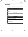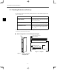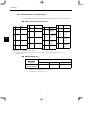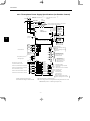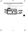
1
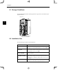
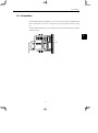
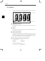
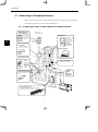
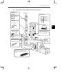
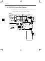
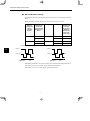
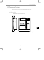
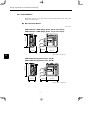
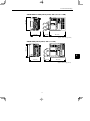
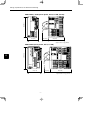
YASKAWA SERIES SGDH FULLY CLOSED INTERFACE UNIT USER'S MANUAL MODEL: JUSP-FC100 YASKAWA MANUAL NO. SIE-C718-5 Safety Information Safety Information The following conventions are used to indicate precautions in this manual. Failure to heed precautions provided in this manual can result in serious or possibly even fatal injury or damage to the products or to related equipment and systems. ! WARNING Indicates precautions that, if not heeded, could possibly result in loss of life or serious injury. ! CAUTION Indicates precautions that, if not heeded, could result in relatively serious or minor injury, damage to the product, or faulty operation. PROHIBITED Indicates actions that must never be taken. The warning symbols for ISO and JIS standards are different, as shown below. ISO JIS The ISO symbol is used in this manual. Both of these symbols appear on warning labels on Yaskawa products. Please abide by these warning labels regardless of which symbol is used. Yaskawa, 1999 All rights reserved. No part of this publication may be reproduced, stored in a retrieval system, or transmitted, in any form, or by any means, mechanical, electronic, photocopying, recording, or otherwise, without the prior written permission of Yaskawa. No patent liability is assumed with respect to the use of the information contained herein. Moreover, because Yaskawa is constantly striving to improve its high-quality products, the information contained in this manual is subject to change without notice. Every precaution has been taken in the preparation of this manual. Nevertheless, Yaskawa assumes no responsibility for errors or omissions. Neither is any liability assumed for damages resulting from the use of the information contained in this publication. iii Visual Aids The following aids are used to indicate certain types of information for easier reference. AEXAMPLE" INFO IMPORTANT TERMS Indicates application examples. Indicates supplemental information. Indicates important information that should be memorized, including precautions such as alarm displays to avoid damaging the devices. Indicates definitions of difficult terms or terms that have not been previously explained in this manual. iv CONTENTS CONTENTS Safety Information . . . . . . . . . . . . . . . . . . . . . . . . . . . . . . . . . . . . . . . . . . . . . . . Visual Aids . . . . . . . . . . . . . . . . . . . . . . . . . . . . . . . . . . . . . . . . . . . . . . . . . . . . . Overview . . . . . . . . . . . . . . . . . . . . . . . . . . . . . . . . . . . . . . . . . . . . . . . . . . . . . . . Using This Manual . . . . . . . . . . . . . . . . . . . . . . . . . . . . . . . . . . . . . . . . . . . . . . . Safety Precautions . . . . . . . . . . . . . . . . . . . . . . . . . . . . . . . . . . . . . . . . . . . . . . 1 2 3 4 iii iv vii viii ix Checking Products and Part Names 1.1 Checking Products on Delivery . . . . . . . . . . . . . . . . . . . . . . . . . . . . . . 1-2 1.2 Product Part Names . . . . . . . . . . . . . . . . . . . . . . . . . . . . . . . . . . . . . . . . 1-3 1.3 Mounting the Option Unit . . . . . . . . . . . . . . . . . . . . . . . . . . . . . . . . . . . 1-4 Installation 2.1 Storage Conditions . . . . . . . . . . . . . . . . . . . . . . . . . . . . . . . . . . . . . . . . . 2-2 2.2 Installation Site . . . . . . . . . . . . . . . . . . . . . . . . . . . . . . . . . . . . . . . . . . . . 2-2 2.3 Orientation . . . . . . . . . . . . . . . . . . . . . . . . . . . . . . . . . . . . . . . . . . . . . . . . . 2-3 2.4 Installation . . . . . . . . . . . . . . . . . . . . . . . . . . . . . . . . . . . . . . . . . . . . . . . . . 2-4 Connectors 3.1 Connecting to Peripheral Devices . . . . . . . . . . . . . . . . . . . . . . . . . . . 3-2 3.1.1 Single-phase (100 V or 200 V) Main Circuit Specifications . . . . . . . . . . . . . . . . . 3.1.2 Three-phase (200 V) Main Circuit Specifications . . . . . . . . . . . . . . . . . . . . . . . . . . 3-2 3-3 3.2 SERVOPACK Internal Block Diagrams . . . . . . . . . . . . . . . . . . . . . . . 3-4 3.3 Fully Closed Encoder Signals Connector (CN4) . . . . . . . . . . . . . . . 3-5 3.3.1 Fully Closed Encoder Connection Example . . . . . . . . . . . . . . . . . . . . . . . . . . . . . . 3.3.2 CN4 Connector Terminal Layout . . . . . . . . . . . . . . . . . . . . . . . . . . . . . . . . . . . . . . . . 3-5 3-6 3.4 Examples of Combined Connections . . . . . . . . . . . . . . . . . . . . . . . . 3-7 3.4.1 Single-phase Power Supply Specifications (for Position Control) . . . . . . . . . . . . 3.4.2 Three-phase Power Supply Specifications (for Position Control) . . . . . . . . . . . . 3-7 3-8 Trial Operation 4.1 Check Items before Trial Operation . . . . . . . . . . . . . . . . . . . . . . . . . . 4-2 4.2 Parameters Required for Trial Operation . . . . . . . . . . . . . . . . . . . . . 4-2 v 5 6 7 Parameter Settings and Functions 5.1 Fully Closed System . . . . . . . . . . . . . . . . . . . . . . . . . . . . . . . . . . . . . . . . 5-2 5.1.1 Fully Closed Control . . . . . . . . . . . . . . . . . . . . . . . . . . . . . . . . . . . . . . . . . . . . . . . . . . 5.1.2 Fully Closed System Specifications . . . . . . . . . . . . . . . . . . . . . . . . . . . . . . . . . . . . . 5-2 5-2 5.2 Setting Parameters . . . . . . . . . . . . . . . . . . . . . . . . . . . . . . . . . . . . . . . . . 5-4 Ratings, Specifications, and Dimensional Drawings 6.1 Ratings and Specifications . . . . . . . . . . . . . . . . . . . . . . . . . . . . . . . . . . 6-2 6.2 Dimensional Drawings . . . . . . . . . . . . . . . . . . . . . . . . . . . . . . . . . . . . . . 6-3 6.2.1 Option Unit . . . . . . . . . . . . . . . . . . . . . . . . . . . . . . . . . . . . . . . . . . . . . . . . . . . . . . . . . . 6.2.2 SERVOPACKs . . . . . . . . . . . . . . . . . . . . . . . . . . . . . . . . . . . . . . . . . . . . . . . . . . . . . . . 6-3 6-4 Troubleshooting 7.1 Troubleshooting Problems with Alarm Displays . . . . . . . . . . . . . . 7-2 7.2 Troubleshooting Problems with No Alarm Display . . . . . . . . . . . . 7-4 vi Overview Overview J About this Manual This manual provides the following information for the Σ-ΙΙ Series SGMjH/SGDH-jE Servodrives. D Procedures for installing and wiring the SERVOPACK and Option Unit. D Procedures for trial operation of the Servodrive. D Ratings and specifications for standard models. D Procedures for maintenance and inspection. J Related Manuals Refer to the following manuals as required. Read this manual carefully to ensure the proper use of Σ-ΙΙ Series Servodrives. Also, keep this manual in a safe place so that it can be referred to whenever necessary. Manual Name Manual Number Σ-II Series SGMjH/SGDH User’s Manual Servo Selection and Data Sheets Σ-ΙΙ Series SGMjH/SGDH User’s Manual Design and Maintenance vii Contents SIE-S800-32.1 Describes the procedure used to select Σ-II Series Servodrives and capacities. SIE-S800-32.2 Provides detailed information on SGDH SERVOPACKs. Using This Manual J Intended Audience This manual is intended for the following users. D Those designing Σ-II Series Servodrive systems. D Those installing or wiring Σ-II Series Servodrives. D Those performing trial operation or adjustments of Σ-II Series Servodrives. D Those maintaining or inspecting Σ-II Series Servodrives. J Description of Technical Terms In this manual, the following terms are defined as follows: D Option Unit = JUSP-FC100 D Servomotor = Σ-ΙΙ Series SGMAH, SGMPH, SGMGH, SGMSH, or SGMDH Servomotor. D SERVOPACK = Σ-ΙΙ Series SGDH-jjjE SERVOPACK. D Servodrive = A set including a Servomotor and Servo Amplifier. D Servo System = A servo control system that includes the combination of a Servodrive with a host computer and peripheral devices. J Indication of Reverse Signals In this manual, the names of reverse signals (ones that are valid when low) are written with a forward slash (/) before the signal name, as shown in the following examples: D /S-ON D /P-CON viii Safety Precautions Safety Precautions The following precautions are for checking products upon delivery, installation, wiring, operation, maintenance and inspections. J Checking Products upon Delivery ! CAUTION D Always use the Servomotor and SERVOPACK in one of the specified combinations. Not doing so may cause fire or malfunction. J Installation ! CAUTION D Never use the products in an environment subject to water, corrosive gases, inflammable gases, or combustibles Doing so may result in electric shock or fire. J Wiring ! WARNING D Connect the SERVOPACK ground terminal effectively to a system grounding conductor or grounding electrode (100Ω or less). Improper grounding may result in electric shock or fire. ! CAUTION D Do not connect a three-phase power supply to SERVOPACK U, V, or W output terminals. Doing so may result in injury or fire. D Securely fasten the power supply terminal screws and motor output terminal screws. Not doing so may result in fire. ix J Operation WARNING ! D Never touch any rotating motor parts while the motor is running. Doing so may result in injury. CAUTION ! D Conduct trial operation on the Servomotor alone with the motor shaft disconnected from machine to avoid any unexpected accidents. Not doing so may result in injury. D Before starting operation with a machine connected, change the settings to match the parameters of the machine. Starting operation without matching the proper settings may cause the machine to run out of control or malfunction. D Before starting operation with a machine connected, make sure that an emergency stop can be applied at any time. Not doing so may result in injury. D Do not touch the heat sinks during operation. Doing so may result in burns due to high temperatures. J Maintenance and Inspection WARNING ! D Never touch the inside of the SERVOPACKs. Doing so may result in electric shock. D Do not remove the panel cover while the power is ON. Doing so may result in electric shock. D Do not touch terminals for five minutes after the power is turned OFF. Residual voltage may cause electric shock. ! CAUTION D Do not disassemble the Servomotor. Doing so may result in electric shock or injury. D Do not attempt to change wiring while the power is ON. Doing so may result in electric shock or injury. x Safety Precautions J General Precautions Note the following to ensure safe application. S The drawings presented in this manual are sometimes shown without covers or protective guards. Always replace the cover or protective guard as specified first, and then operate the products in accordance with the manual. S The drawings presented in this manual are typical examples and may not match the product you received. S This manual is subject to change due to product improvement, specification modification, and manual improvement. When this manual is revised, the manual code is updated and the new manual is published as a next edition. The edition number appears on the front and back covers. S If the manual must be ordered due to loss or damage, inform your nearest Yaskawa representative or one of the offices listed on the back of this manual. S Yaskawa will not take responsibility for the results of unauthorized modifications of this product. Yaskawa shall not be liable for any damages or troubles resulting from unauthorized modification. xi 1 Checking Products and Part Names This chapter describes the procedure for checking Σ-II Series products and the Option Unit upon delivery. It also describes the names of product parts. 1.1 Checking Products on Delivery . . . . . . . . . . 1.2 Product Part Names . . . . . . . . . . . . . . . . . . . 1.3 Mounting the Option Unit . . . . . . . . . . . . . . . 1 -1 1-2 1-3 1-4 1 Checking Products and Part Names 1.1 Checking Products on Delivery The following procedure is used to check products upon delivery. Check the following items when products are delivered. Check Items 1 Comments Are the delivered products the ones that were ordered? Check the model numbers marked on the nameplates of the Option Unit. (Refer to the descriptions of model numbers on following pages) Is there any damage? Check the overall appearance, and check for damage or scratches that may have occurred during shipping. Can the Option Unit be installed on the SERVOPACK used? Check the model number given on the SERVOPACK nameplate. The model number must contain “SGDH” and “E” as shown below to support the Option Unit. SGDH-jjjE-j If any of the above items are faulty or incorrect, contact your Yaskawa sales representative or the dealer from whom you purchased the products. J External Appearance and Nameplate Examples Option Unit model number Option Unit Name SERVOPACK FC100 FULLY-CLOSED MODEL S/N I/F UNIT JUSP-FC100 VER. 000000 V81003-69 YASKAWA ELECTRIC MADE IN JAPAN C N 4 Serial number Figure 1.2 Figure 1.1 External Appearance of the Option Unit 1 -2 Version Nameplate 1.2 Product Part Names J Model Numbers Option Unit JUSP − FC10 0 SERVOPACK peripheral device Type of device: FC10 Fully Closed Interface Unit Design Revision Order 1.2 Product Part Names The following diagram illustrates the product part names of the Option Unit. Ground wire: Connect to the terminal marked as “G” on the SGDH SERVOPACK. FC100 Nameplate: Indicates the model and serial numbers of the Option Unit. CN4 Connector: Used for fully closed encoder. C N 4 Figure 1.3 Option Unit 1 -3 1 Checking Products and Part Names 1.3 Mounting the Option Unit Mount a fully closed I/F unit type JUSP-FC100 on a SGDH SERVOPACK in the following manner. Provide the screws for connecting ground wire as shown below. 1 Mounting Method Base mounted Rack mounted Duct ventilated SERVOPACK Type Screw Remarks SGDH-A3 to 02BE SGDH-A3 to 10AE M3 × 10 round head screws (with spring washer and plain washer) SGDH-15 to 50AE M4 × 10 round head screw SGDH-05 to 30DE (with spring washer and plain washer) SGDH-60/75AE M4 × 8 round head screws (with spring washer and plain washer) SGDH-A3 to 02BE-R M4 × 6 round head screws SGDH-A3 to 50AE-R (with spring washer and SGDH-05 to 30DE-R plain washer) SGDH-60/75AE-P M4 × 8 round head screws (with spring washer and plain washer) Must be provided by customer. Must be provided by customer. Use the screw of the front panel. Must be provided by customer. Note : Make sure that spring washers and plain washers are used for mounting. (Otherwise, the screw for connecting ground wire sticks out from the other side of the flange, and the SERVOPACK cannot be mounted properly.) Use the screw of the front panel. 1. Remove the connector cover from the CN10 connector on the SERVOPACK. CN10 YASKAWASERVOPACK SGDH− Connector cover MODE/SET DATA/ CHARGE POWER 2. Mount the Option Unit on the SERVOPACK. SERVOPACK connector CN10 Connector (Connect to SERVOPACK) YASKAWASERVOPACK SGDH− FC100 C N 4 1 -4 1.3 Mounting the Option Unit 3. For grounding, connect a ground wire of the Option Unit to the point marked “G” on the SERVOPACK. GROUND WIRE “G” YASKAWA SERVOPACK SGDH− MODE/SET CHARGE FC100 1 DATA/ POWER For SERVOPACK (30 W to 5.0 kW) “G” GROUND WIRE YASKAWA SERVOPACK 200V SGDH − NS100 For SERVOPACK (6.0 kW to 7.5 kW) When the Option Unit has been mounted correctly, the SERVOPACK will appear as shown in the following diagram. YASKAWA SERVOPACK 200V SGDH− FC100 C N 4 1 -5 2 Installation This chapter describes precautions for Σ-II Series product installation. The SGDH SERVOPACKs are base-mounted servo controller. Incorrect installation will cause problems. Always observe the installation precautions shown in this chapter. 2.1 2.2 2.3 2.4 Storage Conditions . . . . . . . . . . . . . . . . . . . . Installation Site . . . . . . . . . . . . . . . . . . . . . . . . Orientation . . . . . . . . . . . . . . . . . . . . . . . . . . . . Installation . . . . . . . . . . . . . . . . . . . . . . . . . . . . 2 -1 2-2 2-2 2-3 2-4 2 Installation 2.1 Storage Conditions Store the SERVOPACK within the following temperature range when it is stored with the power cable disconnected. −20 to 85°C YASKAWA SERVOPACK 200V SGDH− FC100 2 C N 4 Σ-II Series SGDH SERVOPACK with Option Unit mounted 2.2 Installation Site Take the following precautions at the installation site. Situation Installation Precaution Installation in a Control Panel Design the control panel size, unit layout, and cooling method so that the temperature around the SERVOPACK does not exceed 55°C. Installation Near a Heating Unit Minimize heat radiated from the heating unit as well as any temperature rise caused by natural convection so that the temperature around the SERVOPACK does not exceed 55°C. Installation Near a Source of Vibration Install a vibration isolator beneath the SERVOPACK to avoid subjecting it to vibration. Installation at a Site Exposed to Corrosive Gas Corrosive gas does not have an immediate effect on the SERVOPACK, but will eventually cause electronic components and contactor-related devices to malfunction. Take appropriate action to avoid corrosive gas. Other Situations Do not install the SERVOPACK in hot or humid locations, or locations subject to excessive dust or iron powder in the air. 2 -2 2.3 Orientation 2.3 Orientation Install the SERVOPACK perpendicular to the wall as shown in the figure. The SERVOPACK must be oriented this way because it is designed to be cooled by natural convection or cooling fan. Secure the SERVOPACK using 2 to 4 mounting holes. The number of holes depends on the SERVOPACK capacity. 2 Wall MADE IN JAPAN Ventilation 2 -3 Installation 2.4 Installation Follow the procedure below to install multiple SERVOPACKs side by side in a control panel. Cooling fan Cooling fan 50 mm (1.97 in) min. 2 30 mm (1.18 in) min. 10 mm (0.39 in) min. 50 mm (1.97 in) min. J SERVOPACK Orientation Install the SERVOPACK perpendicular to the wall so that the front panel (containing connectors) faces outward. J Cooling As shown in the figure above, provide sufficient space around each SERVOPACK for cooling by cooling fans or natural convection. J Side-by-side Installation When installing SERVOPACKs side by side as shown in the figure above, provide at least 10 mm (0.39 in) between and at least 50 mm (1.97 in) above and below each SERVOPACK. Install cooling fans above the SERVOPACKs to maintain a constant temperature inside the control panel and to prevent an excessive temperature rise around each SERVOPACK. J Environmental Conditions in the Control Panel D Ambient Temperature: 0 to 55°C D Humidity: 90% RH or less D Vibration: 0.5 G (4.9 m/s2) D Condensation and Freezing: None D Ambient Temperature for Long-term Reliability: 45°C max. 2 -4 3 Connectors This chapter describes the procedure used to connect Σ-II Series products to peripheral devices when an Option Unit is mounted and provides examples of combined connections. 3.1 Connecting to Peripheral Devices . . . . . . . . 3-2 3.1.1 Single-phase (100 V or 200 V) Main Circuit Specifications . . . . . . . . . . . . . . . . . . . . . . . . . . . . . 3.1.2 Three-phase (200 V) Main Circuit Specifications . 3-2 3-3 3.2 SERVOPACK Internal Block Diagrams . . . 3.3 Fully Closed Encoder Signals Connector (CN4) . . . . . . . . . . . . . . . . . . . . . . . . . . . . . . . 3-4 3.3.1 Fully Closed Encoder Connection Example . . . . . 3.3.2 CN4 Connector Terminal Layout . . . . . . . . . . . . . . . 3-5 3-6 3.4 Examples of Combined Connections . . . . . 3-7 3.4.1 Single-phase Power Supply Specifications (for Position Control) . . . . . . . . . . . . . . . . . . . . . . . 3.4.2 Three-phase Power Supply Specifications (for Position Control) . . . . . . . . . . . . . . . . . . . . . . . 3 -1 3-5 3-7 3-8 3 Connectors 3.1.1 Single-phase (100 V or 200 V) Main Circuit Specifications 3.1 Connecting to Peripheral Devices This section provides examples of standard Σ-II Series product connections to peripheral devices. It also briefly explains how to connect each peripheral device. 3.1.1 Single-phase (100 V or 200 V) Main Circuit Specifications Molded-case Circuit Breaker (MCCB) Protects the power line by shutting the circuit OFF when overcurrent is detected. 3 Power supply Single-phase 200 VAC R T Digital Operator JUSP-OP02A-2 Allows the user to set parameters or operation references and to display operation or alarm status. Communication is also possible with a personal computer. Molded-case circuit breaker Noise Filter Used to eliminate external noise from the power line. Personal Computer Noise filter Cable model: JZSP-CMS01 to 03 Magnetic Contactor Fully Closed Encoder HI Series Turns the servo ON and OFF. Install a surge suppressor on the magnetic contactor. Connector kit model: JZSP-VEP02 Magnetic contactor U V W Power supply ground line Power Supply for Brake Used for a Servomotor with a brake. Magnetic contactor L1 L2 Brake power supply L1C L2C B1 B2 Regenerative resistor (option) Regenerative Resistor Connect an external regenerative resistor to terminals B1 and B2 if the regenerative capacity is insufficient. 3 -2 Encoder Cable Encoder Connector 3.1 Connecting to Peripheral Devices 3.1.2 Three-phase (200 V) Main Circuit Specifications Molded-case Circuit Breaker (MCCB) Power supply Three-phase 200 VAC R S T Protects the power line by shutting the circuit OFF when overcurrent is detected. Digital Operator JUSP-OP02A-2 Allows the user to set parameters or operation references and to display operation or alarm status. Communication is also possible with a personal computer. Molded-case circuit breaker Noise Filter Used to eliminate external noise from the power line. Personal Computer 3 Noise filter Cable model: JZSP-CMS01 to 03 Magnetic Contactor Fully Closed Encoder HI Series Turns the servo ON and OFF. Install a surge suppressor on the magnetic contactor. Connector kit model: JZSP-VEP02 Magnetic contactor U V W Power supply ground line Power Supply for Brake Used for a Servomotor with a brake. Magnetic contactor Brake power supply Encoder Cable Encoder Connector L1 L2 L3 L1C L2C B1 B2 Regenerative resistor (optional) Regenerative Resistor If the capacity of the internal regenerative resistor is insufficient, remove the wire between B2 and B3 and connect an external regenerative resistor to terminals B1 and B2. 3 -3 Connectors 3.2 SERVOPACK Internal Block Diagrams The following sections show an internal block diagram for the SERVOPACK with an Option Unit. 30 to 400 W 200-V and 30 to 200 W 100-V Models Single−phase+10% 200 to 230 V − 15% (50/60Hz) 1 B1 B2 2 PM−1 3 C1 XX1 V Voltage Sensor Gate drive Voltage Sensor Gate drive over− current protector ∼ + ∼ − + − Current Sensor ± 5V DC/DC con− verter +15 V For battery connection CN8 ASIC (PWM control) + 5V PG CN2 Interface ± 12 V CN1 +5 V 1MC 0V 1MC Surge suppressor (5RY) W N2 Relay drive Power Power OFF ON V R8 W TR1 N1 L2C U U + − T L1C R7 D1 CHARGE R L2 AC Servomotor P2 FU1 1MC D2D3D4 PM1−2 P1 Line filter L1 THS1 RY1 Open during servo alarm Monitor display POWER Analog voltage converter CN5 Analog monitor output for su− pervision CN3 CPU (position and speed calculations) I/O Sequence I/O CN10 Digital Operator personal computer CN10 Fully closed PG CN4 Power supply 3 -4 3.3 Fully Closed Encoder Signals Connector (CN4) 3.3 Fully Closed Encoder Signals Connector (CN4) This section describes the wiring required to connect the fully closed encoder signals connector (CN4) to the fully closed encoder. 3.3.1 Fully Closed Encoder Connection Example The following diagram shows an example of CN4 connections. SERVOPACK CN4 Input line receiver Made by TI SN75175 Fully closed PG 16 FA 17 /FA 18 FB 19 /FB 14 FC 15 /FC 1 0V P P SG P Phase A Phase B Phase C 0V FG Connector shell P: Twisted pair cable Note The SERVOPACK does not provide power supply for the fully closed PG, so it must be provided by the customer. 3 -5 3 Connectors 3.3.2 CN4 Connector Terminal Layout 3.3.2 CN4 Connector Terminal Layout The following diagram shows the CN4 connector terminal layout and connector specifications. J CN4 Connector Terminal Layout 2 4 SG GND − − 1 SG GND 3 SG GND 5 6 − − − − − 18 FB 9 − 10 − − Fully closed PG input for phase C 16 FA 7 − − 14 FC − 3 8 − 12 11 − − 13 − − 15 /FC Fully closed PG input for phase A Fully closed PG input p for phase C 17 /FA Fully closed PG input for phase B Fully closed PG input for phase A 19 /FB Fully closed PG input for phase B − − 20 − − Note 1. Do not connect anything to empty terminals. 2. Connect the cable shield to the connector shell. It is connected to the frame ground (FG) through the connector on the SERVOPACK end. J CN4 Specifications Specifications for SERVOPACK Connectors 10220-52A2JL 20-pin Right Angle Plug Applicable Receptacles Soldered 10120-3000VE Case 10320-52A0-008 Manufacturer SUMITOMO 3M LTD. Note 1. Use shielded twisted pair cables with AWG24 or AWG26 wires. The finished cable outside diameter must be 11.6 mm max. 2. The JZSP-VEP02 Connector Kit is available. 3 -6 3.4 Examples of Combined Connections 3.4 Examples of Combined Connections The following diagrams show examples of combined connections. 3.4.1 Single-phase Power Supply Specifications (for Position Control) T R Single-phase 200 to 230 VAC (50/60 Hz) + 10% –15% or Single-phase 110 to 115 VAC (50/60 Hz) + 10% –15% 1MCCB Noise filter Power Power OFF ON 1MC Be sure to attach a surge suppressor to the excitation coil of the magnetic contactor and relay. SUP 1MC 1MC Alarm processing B1 B2 B3 A(1) Servomotor B(2) M C(3) D(4) U L1 V W L2 L1C L2C 1 SGDH SERVOPACK Optical encoder CN2 PG 2 G Connect to ground. Be sure to prepare the end of shield properly. *4. CN1 Fully closed speed and position detector CN4 PG JUSP-FC100 Option Unit PULS CW Phase A SIGN CCW PULS P*PULS 8 ~ 37 SIGN 11 P *SIGN 12 Phase B CLR 15 P*CLR 14 *1. 3 1 kΩ Power supply PL1 for open col- PL2 13 18 lector referPL3 ence BAT(+) Backup battery 2.8 to 4.5V*2 21 + P BAT(−) 22 − Position reference Fully closed PG power supply 7 150Ω ~ CLR SEN signal input*2 +5V 0V +24 V Servo ON when 1Ry turns ON P operation when 2Ry turns ON Reverse run prohibited when N-LS turns OFF Forward run prohibited when P-LS turns OFF Alarm reset when 3Ry turns ON Reverse run current limit ON when 6Ry turns ON Forward run current limit ON when 7Ry turns ON SEN P SG +24 V 1Ry +12 V 7Ry P control (P operation) Reverse run prohibited Forward run prohibited Alarm reset Reverse current limit ON Forward current limit ON /N−CL 46 /P−CL PAO *PAO 35 36 PBO *PBO 1 3Ry /ALM−RST44 6Ry 33 34 PG dividing ratio output Applicable line receiver: SN75175 made by TI or MC3486 equivalent PCO *PCO PSO *PSO *3. SG Servo ON 2Ry /P−CON 41 42 ALO3 48 49 47 3.3 kΩ P−LS P−OT 39 19 20 /S−ON 40 43 ALO2 ~ 4 2 N−LS N−OT Alarm code output Maximum operating voltage: 30 VDC Maximum operating current: 20 mA DC ALO1 38 45 ~ 25 /COIN+ 26 /COIN− 27 ~ 28 29 ~ 30 31 ~ 32 Phase-S rotation count Serial data output Applicable line receiver: SN75175 made by TI or MC3486 equivalent Positioning completed (ON when positioning has been completed) /TGON+ TGON output /TGON− (ON when the set value is exceeded) /S−RDY+ Servo ready output /S−RDY− (ON when ready) ALM+ ALM− Connector shell FG Connect shield to connector shell. Servo alarm output (OFF for an alarm) Photocoupler Outputs Maximum operating voltage: 30 VDC Maximum operating current: 50 mA DC * 1. ↕P represents twisted-pair wires. * 2. Connect when using an absolute encoder. * 3. Valid when using an absolute encoder. * 4. Connect the ground wire of the Option Unit to the point marked “G” on the SERVOPACK. (Refer to 1.3 Mounting the Option Unit.) 3 -7 3 Connectors 3.4.2 Three-phase Power Supply Specifications (for Position Control) 3.4.2 Three-phase Power Supply Specifications (for Position Control) R T S 1MCCB Noise filter Three-phase 200 to 230 VAC (50/60 Hz) 1MC or Three-phase 100 to 115 VAC (50/60 Hz) Be sure to attach a surge suppressor to the excitation coil of the magnetic contactor and relay. SUP B1 B2 B3 A(1) Servomotor B(2) M C(3) D(4) U L1 L2 V W L3 SGDH SERVOPACK L1C L2C 1 + 10% –15% Alarm processing Power Power OFF ON 1MC 1MC + 10% –15% Optical encoder CN2 PG 2 G Connect to ground. 3 Be sure to prepare the end of shield properly. *4. CN1 Fully closed speed and position detector CN4 PG JUSP-FC100 Option Unit PULS P*PULS 8 Phase A SIGN CCW CLR 15 P*CLR 14 *1. 3 1 kΩ Power supPL1 ply for open 13 PL2 collector ref18 PL3 erences + − +5 V SEN signal input*2 0V +24 V P operation when 2Ry turns ON Reverse run prohibited when N-LS turns OFF Reverse run prohibited when P-LS turns OFF Alarm reset when 3Ry turns ON Reverse current limit ON when 6Ry turns ON Forward current limit ON when 7Ry turns ON 37 38 ~ 39 CLR Backup battery 2.8 to 4.5V*2 Servo ON when 1Ry turns ON ~ SIGN 11 P *SIGN 12 Phase B Position reference Fully closed PG power supply 7 150 Ω PULS CW +12 V BAT(+) 21 P BAT(−) 22 SEN 4 P 2 SG +24 V 1Ry ~ 47 3.3 kΩ P−LS P−OT 42 P control (P operation) Reverse run prohibited Forward run prohibited 3Ry /ALM−RST44 Alarm reset 6Ry Reverse current limit ON Forward current limit ON 7Ry /N−CL 46 /P−CL PAO *PAO 35 36 PBO *PBO 19 20 PCO *PCO 48 49 PSO *PSO 1 2Ry /P−CON 41 43 33 34 PG dividing ratio output Applicable line receiver: SN75175 made by TI or MC3486 equivalent *3. SG Servo ON /S−ON 40 N−LS N−OT Alarm code output Maximum operating voltage: 30 VDC ALO3 Maximum operating current: 20 mA DC ALO1 ALO2 45 ~ 25 /COIN+ 26 /COIN− 27 ~ 28 29 ~ 30 31 ~ Connector shell 32 /TGON+ /TGON− Phase-S rotation count Serial data output Applicable line receiver: SN75175 made by TI or MC3486 equivalent Positioning completed (ON when positioning is completed) TGON output (ON when the set value is exceeded) /S−RDY+ Servo ready output /S−RDY− (ON when ready) ALM+ ALM− FG Connect shield to connector shell. Servo alarm output (OFF for an alarm) Photocoupler output Maximum operating voltage: 30 VDC Maximum operating current: 50 mA DC * 1. ↕P represents twisted-pair wires. * 3. Valid when using an absolute encoder. * 2. Connect when using an absolute encoder. * 4. Connect the ground wire of the Option Unit to the point marked “G” on the SERVOPACK. (Refer to 1.3 Mounting the Option Unit.) 3 -8 4 Trial Operation This chapter describes the check items before trial operation and the parameters required for trial operation. 4.1 Check Items before Trial Operation . . . . . . . . . . 4.2 Parameters Required for Trial Operation . . . . . 4 -1 4-2 4-2 4 Trial Operation 4.1 Check Items before Trial Operation Conduct trial operation after wiring has been completed. Inspect and check the following items when performing trial operation, and be sure to conduct trial operation safely. Refer to Chapter 4 Trial Operation of the Σ-II Series SGMjH/SGDH User’s Manual (SIES800-32.2) for details on trial operation. D Before conducting trial operation for fully closed control, check the fully closed encoder and other relevant settings. If the settings are incorrect, there will be a risk of the motor going out of control. Conduct initial trial operation by setting the Pn505 parameter (overflow level) to 1 (minimum value) to check the operation at low speed. 4.2 Parameters Required for Trial Operation 4 This section describes the minimum parameters required for trial operation with fully closed encoder specifications. J Parameters Refer to 7.1.6 Operation in User Constant Setting Mode of the Σ-II Series SGMjH/SGDH User’s Manual (SIE-S800-32.2) for details on the setting of each parameter. Turn OFF power once after changing any parameter. The change will be valid when power is turned ON again. Pn202 Electronic Gear Ratio (Numerator) See 5.2 Pn203 Electronic Gear Ratio (Denominator) See 5.2 Changing Servomotor Rotation Direction Use the following parameter to reverse the direction of rotation. Pn000.0 Function Selection Basic Switches: Direction Selection See 5.2 Fully Closed Encoder Specifications Use the following parameters to conduct trial operation with fully closed encoder specifications. Pn002.3 Usage of fully closed encoder See 5.2 Pn206 Number of fully closed pulses See 5.2 4 -2 5 Parameter Settings and Functions This chapter describes how to set parameters and use functions when using fully closed system specifications. 5.1 Fully Closed System . . . . . . . . . . . . . . . . . . . 5-2 5.1.1 Fully Closed Control . . . . . . . . . . . . . . . . . . . . . . . . . 5-2 5.1.2 Fully Closed System Specifications . . . . . . . . . . . . 5-2 5.2 Setting Parameters . . . . . . . . . . . . . . . . . . . . 5-4 5 -1 5 Parameter Settings and Functions 5.1.2 Fully Closed System Specifications 5.1 Fully Closed System 5.1.1 Fully Closed Control In previous SERVOPACKs, a semi-closed method was used to control the motor. In the SGDH SERVOPACK, however, a fully closed loop can be created using the parameter settings. With this function even more precise control is achieved because control involves the detection of the position and speed of actual machine operation. Fully closed control Torque Mechanism including backlash and friction Servomotor Speed and control at the machine end Power Load torque Current Speed, position Detection current Controlled machine 5 Parameters must be set when using fully closed control. Refer to 5.2 Setting Parameters for details. 5.1.2 Fully Closed System Specifications This section describes the fully closed system specifications of the SGDH SERVOPACK when an Option Unit is mounted. J Fully Closed Encoder Pulse Output Form 5-V Differential line driver output (complies with EIA Standard RS-422A) J Fully Closed Encoder Pulse Signal Form 90° Phase difference 2-phase differential pulse: phase A, phase B Maximum receivable frequency for SERVOPACK: 1 Mbps Phase A Phase B t1 t2 t3 t1,t2,t3,t4 > = t4 Forward rotation 5 -2 0.2 µs Reverse rotation 5.1 Fully Closed System J Encoder Signal Output from SERVOPACK If settings are made to use fully closed encoder pulses (refer to 5.2 Setting Parameters), the PAO, PBO, and PCO output signal terminals of the CN1 connector on the SGDH SERVOPACK will directly output fully closed encoder pulses. Encoder dividing ratio settings will be ignored. If settings are made to use fully closed encoder pulses in reverse rotation mode, PBO output signals will be inverted. J Control Mode Fully closed control is applicable to position control mode only. This mode can be switched to another control mode during operation. Refer to 5.3.5 Control Mode Selection of the Σ-II Series SGMjH/SGDH User’s Manual (SIE-S800-32.2) for details. If position control mode is switched to another control mode, semi-closed control will be performed, which differs from ordinary control with regard to the following points. D PAO, PBO, and PCO output signals are fully closed encoder pulses. D Fully closed encoder open circuit can be detected. J Selecting Motor Encoders Either incremental or absolute encoders can be used. When using an absolute encoder, note that semi-closed control differs from ordinary control with regard to the following points. D No SEN signal input is required. D The PAO signal does not contain absolute value information (fully closed encoder pulses will be output). If absolute value information on the motor encoder is required, use the PSO signal. 5 -3 5 Parameter Settings and Functions 5.2 Setting Parameters This section describes the parameters that must be set when using an Option Unit. J Fully Closed Encoder Set the method for using the fully closed encoder. Pn002.3 Fully Closed Encoder Usage Method Factory Setting: Position Control 0 The setting details are as follows: Parameters Pn002.3 5 Setting 0 (Factory setting) Meaning Fully closed encoder is not used. 1 Fully closed encoder is used without phase C. 2 Fully closed encoder is used with phase C. 3 Fully closed encoder is used in Reverse Rotation Mode without phase C. 4 Fully closed encoder is used in Reverse Rotation Mode with phase C. Setting this parameter to 0 allows operation to be performed in ordinary semi-closed control mode. When changes have been made to this parameter, turn OFF the power once. The set value will become effective when the power is turned ON again. J Number of Fully Closed Encoder Pulses Set the number of fully closed encoder pulses for each motor rotation. When the number of fully closed encoder pulses per motor rotation is not an integer, set the closest integer. Error will occur in the speed monitor for position loop gain, feed forward, and reference pulse, but no position displacement will occur. Set the number of pulses with a multiplication factor of 1. Pn206 Number of Fully Closed Encoder Pulses Unit P/R Setting Range: Factory Setting: 513 to 65535 16384 Position Control When changes have been made to this parameter, turn OFF the power once. The set value will become effective when the power is turned ON again. 5 -4 5.2 Setting Parameters J Electronic Gears The electronic gear settings for fully closed operation are different from those for semi-closed operations. For information on the parameters, refer to 5.2.5 Using the Electronic Gear Function of the Σ-II Series SGMjH/SGDH User’s Manual (SIE-S800-32.2). SERVOPACK Position reference pulse Encoder signal output ×1 ×2 ×4 Electronic gear Speed current loop Deviation counter ×4 Servomotor PG Machine Fully closed PG 5 5 -5 Parameter Settings and Functions J Reverse Rotation Settings The settings shown in the following table must be made in order to used the Reverse Rotation Mode. Making the settings carefully. Errors may cause the motor to run out of control. Direction of Motor as Viewed from Load for Forward Rotation Relation Pn000.0 Setting Pn002.3 Setting between Fully Closed PG during Forward Rotation Input Phase CCW direction Figure 5.1 0 Figure 5.2 CW direction Figure 5.1 1 Figure 5.2 Phase A Figure 5.1 2, 4 Figure 5.2 1, 3 Figure 5.1 2, 4 Figure 5.2 Phase A Phase B Phase B Figure 5.1 1, 3 Fully Closed PG Input Fully Closed PG Input 5 Relation Between Fully Closed PG during CCW Rotation as Viewed from Motor load Input Phase Time Figure 5.2 Time Both Pn000.0 and Pn002.3 can be used to change the rotational direction during normal operation. If the motor runs out of control, change either Pn000.0 or Pn002.3. When Pn002.3 is set to 2 or 4, PBO output signals will be inverted. 5 -6 6 Ratings, Specifications, and Dimensional Drawings This chapter provides the ratings, specifications, and dimensional drawings of the Option Unit. 6.1 Ratings and Specifications . . . . . . . . . . . . . . 6.2 Dimensional Drawings . . . . . . . . . . . . . . . . . 6-2 6-3 6.2.1 Option Unit . . . . . . . . . . . . . . . . . . . . . . . . . . . . . . . . . 6-3 6.2.2 SERVOPACKs . . . . . . . . . . . . . . . . . . . . . . . . . . . . . . 6-4 6 -1 6 Ratings, Specifications, and Dimensional Drawings 6.1 Ratings and Specifications The following table shows ratings and specifications for the Option Unit. Table 6.1 Option Unit Ratings and Specifications Details Item Applicable SERVOPACK All SGDH-jjjE models Installation Method Mounted on the SGDH SERVOPACK. Basic Specifications Power Consumption 0.5 max. [W] External Dimensions 20 × 142 × 128 (W × H × D) [mm] Approx. Mass [kg] (lb) Fully Closed System Fully Closed Encoder Pulse Specifications Output Form 6 Internal Functions 0.2 (0.44) 5-V differential line driver output (complies with EIA Standard RS-422A) Fully Closed Encoder Pulse Signal Form 90° Phase difference 2-phase differential pulse (phase A, phase B) Maximum Receivable Frequency for SERVOPACK 1 Mbps Power Supply for Fully Closed Encoder To be prepared by customer Protection Fully closed encoder open circuit detection Reverse Rotation Set by parameters 6 -2 6.2 Dimensional Drawings 6.2 Dimensional Drawings Dimensional drawings of the Option Unit and SERVOPACKs are shown below. 6.2.1 Option Unit Dimensions of the Option Unit are shown below. (24 (0.94)) 142 (5.59) FC100 6 20 (0.79) 128 (5.04) 6 -3 Approx. mass: 0.2 kg (0.44 lb) Ratings, Specifications, and Dimensional Drawings 6.2.2 SERVOPACKs 6.2.2 SERVOPACKs Dimensional drawings of the Base-mounted Standard SERVOPACKs (with Option Unit mounted) are shown below. J Base-mounted Models Unit: mm (in) SGDH-A3AE to -02AE (Single-phase, 200 V, 30 to 200 W) SGDH-A3AE to -01BE (Single-phase, 100 V, 30 to 100 W) Ver. 160 (6.30) FC100 MADE IN JAPAN (75 (2.95)) 75 (2.95) 130 (5.12) Approx. mass: 1.0 kg (2.21 lb) 6 SGDH-04AE (Single-phase, 200 V, 400 W) SGDH-02BE (Single-phase, 100 V, 200 W) FC100 160 (6.30) Ver. MADE IN JAPAN 95 (3.74) (75 (2.95)) 130 (5.12) Approx. mass: 1.3 kg (2.87 lb) 6 -4 6.2 Dimensional Drawings SGDH-05AE to-10AE (Three-phase, 200 V, 0.5 to 1.0 kW) Ver. 160 (6.30) FC100 MADE IN JAPAN 110 (4.33) (75 (2.95)) 180 (7.09) Approx. mass: 1.9 kg (4.19 lb) SGDH-15AE (Three-phase, 200 V, 1.5 kW) FC100 Y MADE IN JAPAN Y 6 Y 160 (6.30) Ver. (75 (2.95)) 130 (5.12) 180 (7.09) Approx. mass: 3.0 kg (6.61 lb) 6 -5 Ratings, Specifications, and Dimensional Drawings 6.2.2 SERVOPACKs SGDH-20AE, -30AE (Three-phase, 200 V, 2.0 kW, 3.0 kW) Ver. FC100 Y Y 250 (9.84) MADE IN JAPAN Y 130 (5.12) (75 (2.95)) 180 (7.09) Approx. mass: 4.0 kg (8.82 lb) SGDH-50AE (Three-phase, 200 V, 5.0 kW) 6 50AE−N1−R FC100 250 (9.84) Ver. 155 (6.10) (75 (2.95)) 230 (9.06) Approx. mass: 5.7 kg (12.57 lb) 6 -6 6.2 Dimensional Drawings SGDH-60AE, -75AE (Three-phase, 200 V, 6.0 kW, 7.5 kW) Ver. POWER CN8 BATTERY FC100 250 (9.84) CN3 L1 L2 + 250 (9.84) 235 (9.25) Approx. mass: 15.0 kg (33.07 lb) 6 -7 6 7 Troubleshooting This chapter describes troubleshooting procedures for Servodrives with an Option Unit. 7.1 Troubleshooting Problems with Alarm Displays . . . . . . . . . . . . . . . . . . . . . . . 7.2 Troubleshooting Problems with No Alarm Display . . . . . . . . . . . . . . . . . . . . . 7-2 7-4 7 7 -1 Troubleshooting 7.1 Troubleshooting Problems with Alarm Displays This section describes alarms that will be added when an Optional Unit is mounted. Refer to the Σ-II Series SGMjH/SGDH User’s Manual (SIE-S800-32.2) for details on alarms not listed in this section. Problems that occur in the Servodrives are displayed on the panel operator as “A.jj” or “CPFjj.” “A.− −,” however, does not indicate an alarm. Refer to the following sections to identify the cause of an alarm and the action to be taken. Contact your Yaskawa representative if the problem cannot be solved by the described procedures. J A.C6 A.C6: Fully Closed Encoder Phase-A/-B Open Circuit Alarm Display and Outputs Alarm Outputs Alarm Code Outputs ALO1 ALO2 ALO3 ON OFF ON ALM Output OFF Note OFF: Output transistor is OFF (alarm state). ON: Output transistor is ON. 7 Status and Remedy for Alarm At power ON D When Servo ON (S-ON) signal turns ON A, B, C, D, E A, B, C, D During Servomotor operation Cause Remedy A Fully closed encoder wiring error, faulty contact, or open circuit. Check the wiring and check that the connector is fully inserted on the encoder side. B There is noise in the fully closed encoder wiring. Separate the fully closed encoder wiring from the main circuit. C The fully closed encoder is defective or OFF. Replace the fully closed encoder or turn ON the power. D SERVOPACK is defective. Replace SERVOPACK. E Although no fully closed encoder is connected, the Pn002.3 parameter is set to 1, 2, 3, or 4. Set the Pn002.3 parameter to 0. 7 -2 7.1 Troubleshooting Problems with Alarm Displays J A.C7 A.C7: Fully Closed Encoder Phase-C Open Circuit Alarm Display and Outputs Alarm Outputs Alarm Code Outputs ALO1 ALO2 ALO3 ON OFF ON ALM Output OFF Note OFF: Output transistor is OFF (alarm state). ON: Output transistor is ON. Status and Remedy for Alarm At power ON D When Servo ON (S-ON) signal turns ON A, B, C, D, E, F A, B, C, D During Servomotor operation Cause Remedy A Fully closed encoder wiring error, faulty contact, or open circuit. Check the wiring and check that the connector is fully inserted on the encoder side. B There is noise in the fully closed encoder wiring. Separate the fully closed encoder wiring from the main circuit. C The fully closed encoder is defective or OFF. Replace the fully closed encoder or turn ON the power. D SERVOPACK is defective. Replace SERVOPACK. E Although no fully closed encoder is connected, the Pn002.3 parameter is set to 1, 2, 3, or 4. Set the Pn002.3 parameter to 0. F Although no fully closed encoder for phase C Set the Pn002.3 parameter to 1 or 3. is connected, the Pn002.3 parameter is set to 2 or 4. J Supplementary Information on A.C6 and A.C7 D When Pn002.3 = 0, neither A.C6 nor A.C7 will be detected. When Pn002.3 = 1 or 3, only A.C6 will be detected. When Pn002.3 = 2 or 4, both A.C6 and A.C7 will be detected. D When Pn002.3 = 1, 2, 3, or 4, open circuit will be detected while the motor is ON even if the control mode is not fully closed control mode (such as jogging mode). D Open circuit is detected when no current flows through the terminating resistor inside the SERVOPACK. Therefore, alarm A.C6 or A.C7 will also be activated when the power supply for the fully closed PG line driver is shut down. 7 -3 7 Troubleshooting 7.2 Troubleshooting Problems with No Alarm Display Refer to the tables below to identify the cause of a problem which causes no alarm display and take the remedy described. Also refer to 9.2.2 Troubleshooting Problems with No Alarm Display of the Σ-II Series SGMjH/ SGDH User’s Manual (SIE-S800-32.2). Contact your Yaskawa representative if the problem cannot be solved by the described procedures. Table 7.1 Symptom Troubleshooting Problems with No Alarm Display Cause Remedy When a command is input, the motor reverses out of control. The fully closed encoder phases are incor- Correct the wiring or the Pn002.3 setting. rect. When a command is input, the motor continues to run. No fully closed encoder pulses are output. Check the fully closed encoder. 7 7 -4 No.4-3(インター) メカトロ製品用 SIE SERIES SGDH FULLY CLOSED INTERFACE UNIT USER'S MANUAL IRUMA BUSINESS CENTER 480, Kamifujisawa, Iruma, Saitama 358-8555, Japan Phone 81-42-962-5696 Fax 81-42-962-6138 YASKAWA ELECTRIC AMERICA, INC. 2121 Norman Drive South, Waukegan, IL 60085, U.S.A. Phone 1-847-887-7000 Fax 1-847-887-7370 MOTOMAN INC. HEADQUARTERS 805 Liberty Lane West Carrollton, OH 45449, U.S.A. Phone 1-937-847-6200 Fax 1-937-847-6277 YASKAWA ELETRICO DO BRASIL COMERCIO LTD.A. Avenida Fagundes Filho, 620 Bairro Saude-Sao Paulo-SP, Brazil Phone 55-11-5071-2552 Fax 55-11-5581-8795 CEP: 04304-000 YASKAWA ELECTRIC EUROPE GmbH Am Kronberger Hang 2, 65824 Schwalbach, Germany Phone 49-6196-569-300 Fax 49-6196-569-398 Motoman Robotics Europe AB Box 504 S38525 Torsas, Sweden Phone 46-486-48800 Fax 46-486-41410 Motoman Robotec GmbH Kammerfeldstraβe 1, 85391 Allershausen, Germany Phone 49-8166-90-100 Fax 49-8166-90-103 YASKAWA ELECTRIC UK LTD. 1 Hunt Hill Orchardton Woods Cumbernauld, G68 9LF, United Kingdom Phone 44-1236-735000 Fax 44-1236-458182 YASKAWA ELECTRIC KOREA CORPORATION Kfpa Bldg #1201, 35-4 Youido-dong, Yeongdungpo-Ku, Seoul 150-010, Korea Phone 82-2-784-7844 Fax 82-2-784-8495 YASKAWA ELECTRIC (SINGAPORE) PTE. LTD. 151 Lorong Chuan, #04-01, New Tech Park Singapore 556741, Singapore Phone 65-6282-3003 Fax 65-6289-3003 YASKAWA ELECTRIC (SHANGHAI) CO., LTD. 4F No.18 Aona Road, Waigaoqiao Free Trade Zone, Pudong New Area, Shanghai 200131, China Phone 86-21-5866-3470 Fax 86-21-5866-3869 YATEC ENGINEERING CORPORATION 4F., No.49 Wu Kong 6 Rd, Wu-Ku Industrial Park, Taipei, Taiwan Phone 886-2-2298-3676 Fax 886-2-2298-3677 YASKAWA ELECTRIC (HK) COMPANY LIMITED Rm. 2909-10, Hong Kong Plaza, 186-191 Connaught Road West, Hong Kong Phone 852-2803-2385 Fax 852-2547-5773 BEIJING OFFICE Room No. 301 Office Building of Beijing International Club, 21 Jianguomenwai Avenue, Beijing 100020, China Phone 86-10-6532-1850 Fax 86-10-6532-1851 TAIPEI OFFICE 9F, 16, Nanking E. Rd., Sec. 3, Taipei, Taiwan Phone 886-2-2502-5003 Fax 886-2-2505-1280 SHANGHAI YASKAWA-TONGJI M & E CO., LTD. 27 Hui He Road Shanghai China 200437 Phone 86-21-6553-6060 Fax 86-21-5588-1190 BEIJING YASKAWA BEIKE AUTOMATION ENGINEERING CO., LTD. 30 Xue Yuan Road, Haidian, Beijing P.R. China Post Code: 100083 Phone 86-10-6233-2782 Fax 86-10-6232-1536 SHOUGANG MOTOMAN ROBOT CO., LTD. 7, Yongchang-North Street, Beijing Economic Technological Investment & Development Area, Beijing 100076, P.R. China Phone 86-10-6788-0551 Fax 86-10-6788-2878 YASKAWA ELECTRIC CORPORATION YASKAWA In the event that the end user of this product is to be the military and said product is to be employed in any weapons systems or the manufacture thereof, the export will fall under the relevant regulations as stipulated in the Foreign Exchange and Foreign Trade Regulations. Therefore, be sure to follow all procedures and submit all relevant documentation according to any and all rules, regulations and laws that may apply. Specifications are subject to change without notice for ongoing product modifications and improvements. MANUAL NO. SIE-C718-5 © Printed in Japan June 2002 99-4 3 02-5① 99-71007