1
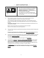
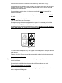
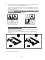
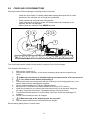
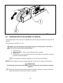
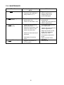
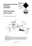
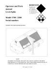
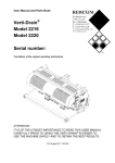
Users’ manual and
parts book
Verti-Clean /
Verti-Clean PTO
Model:
Serial number:
Translation of the original operating
instructions
ATTENTION:
FOR SAFE USE OF THE MACHINE AND FOR THE BEST RESULTS IT IS VERY
IMPORTANT THAT THIS USER’S MANUAL IS READ METICULOUSLY BEFORE USE OF
THE VERTI-CLEAN.
1112 English 947.120.208
PREFACE
Congratulations on your Verti-Clean purchase. For safe and long-lasting operation of this VertiClean it is necessary to read and understand this user’s manual.
Without full knowledge of the contents it is impossible to work with this machine safely.
The following page deals with the general safety instructions first. Every user must know these
and use them. After this a registration card is entered that needs to be returned in order to be
able to deal with later claims.
In this users’ manual many instructions are given, which are numbered in order. You should act
according to this order. If a
means a tip and/or note.
is used, this points to safety instructions. If a
is used, this
All information and technical specifications provided at the moment that this document is
published are the most recent ones. Design specifications may be changed without prior notice.
This document is a translation of the original operating instructions.
Upon request, the original operating instructions are available in Dutch.
WARRANTY PROVISIONS
THIS VERTI-CLEAN IS SUPPLIED WITH A WARRANTY AGAINST DEFECTS IN MATERIALS.
THIS WARRANTY IS VALID FOR A PERIOD OF 12 MONTHS FROM THE PURCHASE DATE.
VERTI-CLEAN WARANTEES ARE SUBJECT TO THE “GENERAL CONDITIONS FOR SUPPLY OF
PLANT AND MACHINERY FOR EXPORT, NUMBER 188”, PUBLISHED UNDER THE AUSPICES OF
THE UNITED NATIONS ECONOMIC COMMISSION FOR EUROPE.
REGISTRATION CARD
For your own information, complete the table below:
Serial number machine
Dealer name
Purchase date
Remarks
2
!
Fig. 1
(1)
SAFETY INSTRUCTIONS
!
Verti-Clean has been designed to be used safely.
This can only be done if the safety instructions
described in this manual are followed fully.
Read and understand (Fig. 1) the manual before
you start using the Verti-Clean.
If the machine is not used as described in the
manual there is the risk of injury and/or damage to
the Verti-Clean.
When using the machine the operator must be competent and must have
competently adjusted the machine to the surface to be treated.
With incompetent usage and damage resulting from it the manufacturer will not
accept any responsibility; all risks associated with this are the sole responsibility of
the user.
Incompetent usage also includes not following the manufacturer’s directions for use,
maintenance or repairs.
Before using the Verti-Clean, first inspect the area to be treated.
Remove loose obstacles and avoid irregularities.
(2)
The Verti-Clean has been manufactured according to the latest technical insights and
is safe for use.
Should the machine be used, maintained or repaired by inexpert persons, then there
is a risk of injury to both the user and third parties. This must be avoided!
(3)
All persons that have been designated by the owner to operate, maintain or repair the
Verti-Clean, must have read and fully understood the user’s manual and especially
the chapter Safety instructions.
The operator is responsible for the safe usage of the Verti-Clean.
(4)
The operator is required to check for visible damage and defects before he/she
starts using the Verti-Clean. Alterations to the Verti-Clean (including its operation)
that influence the safety negatively must be remedied immediately.
Making alterations or additions to the Verti-Clean (excluding those approved by the
manufacturer) are not permitted, in principle, for safety reasons.
If modifications to the Verti-Clean have been made, then the current CE mark is
cancelled and whoever made these modifications must apply for a new CE mark
himself.
3
Check the Verti-Clean for loose bolts/ nuts/ parts every time before using it.
If present, check the hydraulic hoses regularly and replace them if they are damaged
or show signs of ageing. The replacement hoses should comply with the technical
demands of the manufacturer.
If present, before work is done to it, the pressure should always be taken off the
hydraulic installation.
In the absence of protective covers and safety stickers the Verti-Clean must NEVER
be used.
NEVER crawl under the Verti-Clean.
Turn the Verti-Clean over if necessary.
When performing maintenance, adjustments or repairs it is necessary to block the
Verti-Clean from sagging/moving/sliding away.
When performing maintenance, adjustments or repairs always turn off the tractor’s
engine and remove the tractor’s key from the ignition. (Fig.2)
Fig. 2
For maintenance and repairs only use original Verti-Clean parts for safety of machine
and operator.
Repairs of the Verti-Clean may only be performed by authorised technical personnel.
Keep an account of repairs.
(5)
Besides the instructions in this user’s manual, the generally safety and instructions
should be followed.
When using the public highway the applicable traffic regulations also apply.
Transporting people is not permitted!
Do not use the Verti-Clean in the darkness, during heavy rainfall/ storms or on slopes
with an angle over 20 degrees.
4
(6)
Before commencing the work, all persons who will operate the Verti-Clean must be
familiar with all its functions and operational elements.
On the sides of the Verti-Clean safety stickers (Fig. 8) are applied with an identical
meaning. These safety stickers must be properly visible and legible at all times, and
be replaced when damaged.
During operation NO persons without the proper personal protective equipment
are permitted in the danger area of the Verti-Clean, because there is danger of
physical injury there from spurting materials (Fig. 3).
Fig. 4
Fig. 3
Bystanders without personal protective equipment must keep a minimum
distance of four metres (4 metres)! (Fig. 4)
Wear functional clothes. Wear heavy shoes with steel toecaps, long trousers, long
hair done up and no loose-fitting clothes.
Use the proper personal protective equipment according to the applicable safety
instructions.
933.280.402
900.280.402
Fig. 5
(7)
Position of safety stickers. (Fig. 5)
5
EU DECLARATION
We – Redexim BV, Utrechtseweg 127, 3702 AC Zeist, Holland – declare entirely under our
own responsibility that the product
VERTI-CLEAN / VERTI-CLEAN PTO WITH A MACHINE NUMBER AS INDICATED ON THE
MACHINE AND INDICATED IN THIS MANUAL
to which this declaration refers, complies with stipulation of the 2006/42/EC machine directive.
Zeist, 25.03.11
A.C. Bos
Manager Operations & Logistics
Redexim Holland
6
TABLE OF CONTENTS
1.0
2.0
3.0
4.0
4.1
4.2
5.0
6.0
7.0
8.0
9.0
10.0
11.0
12.0
13.0
13.1
14.0
14.1
14.2
14.3
PREFACE ........................................................................................................................ 2
WARRANTY PROVISIONS ............................................................................................. 2
REGISTRATION CARD ................................................................................................... 2
! SAFETY INSTRUCTIONS !.................................................................................... 3
EU DECLARATION ......................................................................................................... 6
TECHNICAL DATA .......................................................................................................... 8
GENERAL DESCRIPTION ............................................................................................... 8
FIRST INSTALLATION .................................................................................................... 9
THE POWER TAKE-OFF (PTO) (Verti-clean PTO) .......................................................... 9
LENGTH OF THE PTO (Verti-clean PTO) .......................................................................10
USING THE PTO(Verti-clean PTO) .................................................................................10
COUPLING / DISCONNECTING .....................................................................................11
WORKING DEPTH ADJUSTMENT OF BRUSH..............................................................12
TRANSPORT OF THE VERTI-CLEAN ............................................................................13
THE DRIVING SPEED ....................................................................................................13
THE USE OF THE VERTI-CLEAN ..................................................................................13
START/STOP PROCEDURE ..........................................................................................13
EMPTYING OF THE DIRT RECEIVING BIN ...................................................................14
PROBLEM ANALYSIS ....................................................................................................15
MAINTENANCE ..............................................................................................................16
CHANGING OF THE VIBRATION SIEVE / ADJUST THE SCOOP PLATE VIBRATION
SIEVE. ............................................................................................................................17
OPTION: DIFFERENT VIBRATION SIEVES ...................................................................18
OPTION: BOGY KIT........................................................................................................18
OPTION: RAKE SECTION ..............................................................................................18
OPTION: MAGNETIC BROOM .......................................................................................18
7
1.0
TECHNICAL DATA
Model
Verti-Clean
Working width
1450mm
Verti-Clean PTO
Working depth (With brush not worn out) 0mm -10mm (0”-0.4”)
Driving speed
Weight
Max. 12km/h (7.4mph) depending on the conditions of
the surface.
111 kg ( 245 lbs)
130 Kg (287lbs)
Contents receiving bin
65 litres (3966.5 cu. inch)
Maximum capacity
14500m2/h (156076 ft2/h)
(Theoretical with speed; 10 Km/h (6.2mph))
Drainage vibrating sieve
5mm x 5mm (0.2 “ x 0.2”)
(Standard delivered)
Shipping dimensions
LxWxH
408 x 1650 x 1360 mm
16.1” x 65” x 53.5”
Oil gearbox
SAE 90
Standard parts
Removable dirt receiving bin.
Ground-hugging dragging brush.
Easily changeable sieve.
Manual cylinder with manual and tool set.
Options
Sieve elements with various drainage dimensions.
Wheel kit.
Magnetic broom.
Rake section.
Rear roller
2.0
GENERAL DESCRIPTION
The Verti-Clean / Verti-Clean PTO is a surface cleaning machine for cleaning artificial turf.
8
3.0
FIRST INSTALLATION
Position A
1
2
1
Fig. 6
The machine is delivered on a pallet in transport position. To prepare the machine for operation
the machine must be taken of the pallet and the 3-points connection must be assembled in the
correct position. This is done as follows: (Fig. 6).
1. Remove nuts and bolts 1 and remove 3-points connection 2.
2. Assemble the 3-points connection 2 as in position A.
3. Assemble the nuts and bolts 1 and tighten everything well.
4.0
THE POWER TAKE-OFF (PTO) (Verti-clean PTO)
The PTO is a very important component. It takes care of the drive from the tractor and safe use of the
machine, provided it is installed and maintained in the correct manner. The PTO has its own CE
certification. Read the PTO manual. This manual is located on the PTO.
Fig. 7
9
4.1
LENGTH OF THE PTO (Verti-clean PTO)
The length of the PTO is very important. If it is too long, it can damage the drive of the tractor
and/or the Verti-Drain®. If the overlapping length of the cylinders becomes less than 150 mm (6”)
at any time, it can damage the PTO.
The length changes when the machine is lifted or when a different tractor is used!
In order to set the PTO on the correct length, when a new one has been purchased or when a
different tractor is used, follow these steps: (see Figure 7)
1.
2.
3.
4.
5.
6.
7.
8.
Measure the distance between the PTO’s connection to the tractor and to
the Verti-Drain, from groove to groove, when the machine is connected to
the tractor and positioned on the ground at the right angle.
Measure the distance B of the PTO in its shortest position from the locking
pin to the locking bolt.
Divide the PTO in two parts and remove the protection cap at both ends.
The ends of the cylinders and the ends of the protection caps must be
made shorter: (B-A) + 75 mm (3”).
Smooth off all components, use some grease, and then assemble all
components.
Mount the PTO on the side of the Verti-Drain.
Attach the other end of the PTO to the tractor.
Check the overlap of the cylinders.
Never use the machine if it has a damaged PTO protection cap. First remove any
damaged parts.
4.2
USING THE PTO(Verti-clean PTO)
The following items must be checked for correct use of the PTO:
1.
While working the angle of the pivot pins may not exceed 30 degrees.
2.
The pivot pins must always be aligned.
3.
The overlap of the cylinders must always be minimum 150 mm.
4.
Never use the machine if it has a damaged PTO protection cap.
5.
For lubrication see section 13.0: Maintenance.
10
5.0
COUPLING / DISCONNECTING
Check procedure before starting the coupling of the Verti-Clean.
−
Check the Verti-Clean for visually observable damage and repair this if a safe
operation of the machine can no longer be guaranteed.
− Check whether all nuts and bolts are tightened.
−
Check whether all protective covers and safety stickers are attached to the
machine and are not damaged.
Without them the machine must NEVER be used.
5
2 3
4
1
Fig. 8
The Verti-Clean can be coupled to the tractor by means of the 3-point linkage.
The method is as follows: (Fig. 11)
1.
2.
3.
4.
5.
Remove the 3-point pin 2.
Reverse the tractor carefully, so the lower connecting arms can be coupled to the
frame.
!! Make sure the tractor is blocked properly and cannot move of its own accord !!
10.
!! Turn off the tractor before dismounting !!
Connect the lower connecting arms with the 3-point pins connecting plate pins 1 and
secure these with the retaining pins supplied.
Set the tractor’s stabiliser to 100 mm sideways stroke.
Mount the PTO 5 between the tractor and the Verti-Clean (PTO version)
Install the forestay on your tractor and unscrew this until it is at the same height as
the upper 3-point top connection 3 (transport setting) of the Verti-Clean.
Connect the forestay with pin 2 on the frame; secure pin 2 with the retaining pin 3
supplied.
Screw in the forestay so that it is charged.
11.
12.
!! Make sure that all the fastening pins are secured !!
Start the tractor and lift the Verti-Clean from the surface.
6.
7.
8.
9.
Disconnecting takes place in reverse order.
11
1
2
Fig. 9
6.0
WORKING DEPTH ADJUSTMENT OF BRUSH
The working depth of the brush can be adjusted through changing the wheels at the front of the
machine.
The procedure is as follows: (see fig.9)
!! Make sure the Verti-Clean is blocked properly and cannot move on its own !!
!! Turn off the tractor before dismounting !!
1.
2.
3.
4.
Unscrew Nut 1.
Adjust the wheel 2 till the correct setting has been reached.
Tighten Nut 1.
Follow point 1 up to and including 3 for the other side of the machine so that the
machine is adjusted parallel.
A set of spanners has been supplied; you can find this in the toolbox.
NEVER set the machine in such a way that damage can occur to the surface to be worked.
! IMPORTANT !
First statically check the working depth of the surface to be worked before using the
machine!
Experience has shown that the best machine setting for top-layer cleaning is when the
hairs of the brush do not touch the fibres of the grass.
12
7.0
TRANSPORT OF THE VERTI-CLEAN
The user is responsible for the transportation of the Verti-Clean behind the tractor on
public highways. Check the national law regarding regulations.
Levied concerning open fields, the machine, can up to with a speed of 20 km hours 12.4
Over open fields, with the machine lifted, the speed must not exceed a maximum of 20
km/hour (12.4 mph), higher speed can be dangerous for the driver bystanders and can
even damage the machine.
Make sure that the upper forestay is connected and under tension in the
transport position! See fig. 7
If not, then serious damaged can be done to the machine.
If the machine is lifted off the ground, at least 20% of the tractor’s weight
must be supported by the front axle.
8.0
THE DRIVING SPEED
The speed of the Verti-Clean up is 12 km / h (7.4mph), but in practice the maximum speed must
be read from the surface to be worked and the desired cleaning.
9.0
THE USE OF THE VERTI-CLEAN
Before the Verti-Clean can be used at a location the following must be checked:
1.
2.
3.
4.
5.
6.
7.
Are there any loose objects present on the field? First remove these.
Are there any slopes? The maximum slope on which work can take place with this
machine is 20 degrees.
Always work from the top downwards.
Is there a danger of flying objects such as for example balls, which distract the
attention of the driver? If so then the Verti-Clean can NOT be used.
Is there a risk on sinking or slipping away? If so, postpone the working until the
circumstances have improved.
When the ground is wet, postpone the activities until the circumstances have
improved.
A field can be worked 2 or 3 times in the same or in different directions to obtain a
better cleaning.
Do not make tight turns, preferably drive straight; the surface can be damaged.
10.0 START/STOP PROCEDURE
The start procedure is VERY important. If this procedure is not conducted as described below, then
serious damage can be done to the surface to be treated/the machine.
The start procedure is as follows:
1. Check the Verti-Clean thoroughly for loose parts and check whether all parts are functioning
properly.
!! If loose parts have been found or if parts do not work properly, then the problems
need to be solved first before using the Verti-Clean !!
2. Drive to the location where the treatment needs to take place.
3. Place the machine on surface to be treated and adjust the working depths of the machine statically
as described in chapter 5.0
13
4. Adjust the forestay pin, if desired in the terrain following working position. See fig. 8
5. Disengage PTO and enter up to speed to 540 rpm (PTO version).
6. Start up the tractor and increase the speed until the correct speed has been reached.
!! Preferably drive in straight lines in connection with possible damage which could
otherwise occur to the surface !!
Stopping is as follows:
1. Reduce the driving and PTO speed and lift the machine from the surface.
2. Drive to the next spot and start the working as discussed above.
11.0 EMPTYING OF THE DIRT RECEIVING BIN
3
2
1
Fig. 10
When the dirt receiving bin is full this must be emptied.
This is done according to the following procedure (See Fig.10):
1. Drive the Verti-Clean to the dumping site for collected waste.
!! Make sure the Verti-Clean is blocked properly and cannot move on its own accord !!
!! Switch off the tractor before continuing !!
2.
3.
4.
5.
Open the tarpaulin 1 by removing the wing nuts 2.
Remove the dirt receiving bin 3 and empty this.
Place the dirt receiving bin 3 back in the machine.
Close the tarpaulin 1 and close this by tightening the wing nuts 2.
Remove the waste according to the applicable conditions of the local legislation.
14
12.0 PROBLEM ANALYSIS
Problem
Overspill material to be
cleaned is caught in the dirt
receiving bin.
Possible Cause
-
Too little cleaning
-
Drive wheel skids.
Sieve does not move / return
Solution
Working depth is adjusted too deep.
Vibration sieve is blocked. Work environment is too
wet.
Vibration sieve too fine.
Working depth is adjusted too shallow.
Sieve has too large a
mesh
Brush is worn out.
-
Too little pressure on the
drive wheel.
-
-
Bearings are stuck.
-
-
Too wet surface.
-
-
Vibrating screen is not
placed well in the
machine.
Drive chain broken
Spring reset mechanism
broken
-
-
Adjust the machine les deep.
Open the vibration sieve.
Wait till the work environment
has dried up.
Use a sieve with a larger
mesh.
Adjust the machine deeper.
Replace the sieve by one with
a smaller mesh.
Replace the Brush
Add pressure to the wheel by
tightening the forestay in
transport position.
Loosen the bearings or
replace these.
Postpone the working till the
surface is dry
-
Position sieve correct into the
machine.
Repair or replace.
Replace spring.
Untidy look of the field after
working.
-
Machine is adjusted too
deep.
-
Adjust the machine less deep.
Cracking sounds when the
machine is operational.
-
Bearings are worn out.
-
Replace the bearings.
Machine takes too many bites in the field
Scoop plate of the sieve is adjusted too deep.
15
Adjust the scoop plate of the
sieve to a higher position. See
Hs 13.2.
13.0 MAINTENANCE
Time-line
Check point /Lubrication
point
Method
Before every use.
-
Check for loose bolts / nuts. Presence and Legibility of
safety stickers. (Fig. 5)
-
Tighten the loose bolts/nuts
with the right torque.
Replace these if not
present/damaged.
After first 20 working hours
(new or repaired).
-
Check the roller bearings
and the drive line.
Check for loose bolts / nuts.
-
If necessary replace these
components.
Tighten the loose bolts/nuts
with the right torque
After every 100 working
hours or annually.
-
After every 500 working
hours
-
Check the roller bearings
and the drive line.
Check for loose bolts / nuts. Check the tension of the
chain in the drive line.
Check the wear and tear of
the brush.
-
-
Lubrication of the drive
chain.
-
-
Replace the gearbox oil
(PTO version)
-
16
If necessary replace worn
out components.
Tighten the loose bolts/nuts
with the right torque
Adjust the tension of the
chain. Or if necessary
replace the chain.
If necessary replace the
brush.
Use a universal chain
lubrication
Use SAE 90
13.1 CHANGING OF THE VIBRATION SIEVE / ADJUST THE SCOOP
PLATE VIBRATION SIEVE.
3
1
2
5
4
Fig. 11
For operation with different materials there are seven sieves available with different meshes
which can be exchanged in the Verti-Clean.
Changing the vibration sieve is done as follows (See Fig. 11):
!! Make sure the Verti-Clean is blocked properly and cannot move on its own !!
1.
2.
3.
4.
5.
6.
7.
Take the vibration sieve/dirt receiving bin from the machine as described in chapter 10.0
Unscrew nuts 1 one turn.
Slide plate 2 upwards.
Slide the sieve 3 out of the frame and place another sieve.
Slide plate 2 downwards so that this encloses the vibration sieve.
Tighten the nuts 1.
Place the vibration sieve/dirt receiving bin back in the machine as described in chapter
10.0.
If the vibration sieve starts taking bites on the filed it is possible that the scoop plate of the
vibration sieve is adjusted too deep. This can be modified as follows: (See Fig. 10)
1. Unscrew nuts 4.
2. Move the scoop plate 5 until the desired height is reached.
3. Tighten the nuts 4.
17
14.0 OPTION: DIFFERENT VIBRATION SIEVES
If there a different type material must be sieved out or the material has other dimensions for
which the standard assembled vibration sieve is not sufficient; then it is possible to assemble
another sieve which has a larger or smaller mesh.
The following sieves are available for the Verti-Clean:
Mesh(mm)
3.2x3.2
4x4
5x5
5.5x5.5
6x6
Mesh(inches)
0.13x0.13
0.16x0.16
0.2x0.2
0.21x0.21
0.24x0.24
Part number
458.441.431
458.441.432
458.441.430 (Standard)
458.441.433
458.441.434
14.1 OPTION: BOGY KIT
If the pulling vehicle does not have a three-point system to lift the Verti-Clean in then it is
possible to provide the Verti-Clean with a towing hook and wheels for transport of the
machine. This option can be ordered under number 247.139.001.
For assembly onto the Verti-Clean see the component handbook.
14.2 OPTION: RAKE SECTION
For raking of a surface a rake section can be delivered.
The rake section consists of a beam with spring pins which can be adjusted to depth. This
option can be ordered under number 247.139.002
For assembly onto the Verti-Clean see the parts handbook.
14.3 OPTION: MAGNETIC BROOM
To take steel particles such as nails/screws/shoe studs from the ground a magnetic broom is
available. This magnetic broom can be adjusted in height and is foldable for easy use after
operation.
This option can be ordered under number 247.139.003.
For assembly onto the Verti-Clean see the parts handbook.
18