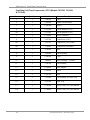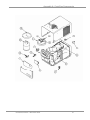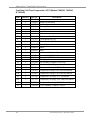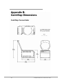
1
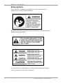
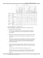
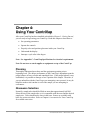
User’s Manual CentriVap Centrifugal Concentrators and Cold Traps Models 7810010 7810011 7810012 7810013 7810014 7810015 7810016 7810017 7811020 7811030 7811040 7982010 7982011 7982012 7984010 7984011 7984012 7460020 7460030 7460040 7983010 7983011 7983012 7475010 7475011 7475012 To receive important product updates register your product online at www.labconco.com/productreg.html or return the attached card and receive FREE LabbyWear ! Labconco’s Mascot, Labby the LABster Labconco Corporation 8811 Prospect Avenue Kansas City, MO 64132-2696 800-821-5525, 816-333-8811 Fax 816-363-0130 E-Mail [email protected] Please read the user’s manual before operating equipment. Copyright © 2005 Labconco Corporation. All rights reserved. The information contained in this manual and the accompanying products are copyrighted and all rights reserved by Labconco Corporation. Labconco Corporation reserves the right to make periodic design changes without obligation to notify any person or entity of such change. Warranty Labconco provides a warranty on all parts and factory workmanship. The warranty includes areas of defective material and workmanship, provided such defect results from normal and proper use of the equipment. The warranty for all Labconco products will expire one year from date of installation or two years from date of shipment from Labconco, whichever is sooner, except the following; • Purifier® Delta® Series Biological Safety Cabinets and PuriCare® Lab Animal Products carry a three-year warranty from date of installation or four years from date of shipment from Labconco, whichever is sooner. • SteamScrubber & FlaskScrubber Glassware Washers carry a two-year warranty from date of installation or three years from date of shipment from Labconco, whichever is sooner. • Carts carry a lifetime warranty. • Glassware is not warranted from breakage when dropped or mishandled. This limited warranty covers parts and labor, but not transportation and insurance charges. In the event of a warranty claim, contact Labconco Corporation or the dealer who sold you the product. If the cause is determined to be a manufacturing fault, the dealer or Labconco Corporation will repair or replace all defective parts to restore the unit to operation. Under no circumstances shall Labconco Corporation be liable for indirect, consequential, or special damages of any kind. This statement may be altered by a specific published amendment. No individual has authorization to alter the provisions of this warranty policy or its amendments. Lamps and filters are not covered by this warranty. Damage due to corrosion or accidental breakage is not covered. Returned or Damaged Goods Do not return goods without the prior authorization from Labconco. Unauthorized returns will not be accepted. If your cabinet was damaged in transit, you must file a claim directly with the freight carrier. Labconco Corporation and its dealers are not responsible for shipping damages. The United States Interstate Commerce Commission rules require that claims be filed with the delivery carrier within fifteen (15) days of delivery. Limitation of Liability The disposal and/or emission of substances used in connection with this equipment may be governed by various federal, state, or local regulations. All users of this equipment are required to become familiar with any regulations that apply in the user’s area concerning the dumping of waste materials in or upon water, land, or air and to comply with such regulations. Labconco Corporation is held harmless with respect to user’s compliance with such regulations. Contacting Labconco Corporation If you have questions that are not addressed in this manual, or if you need technical assistance, contact Labconco’s Customer Service Department or Labconco’s Product Service Department at 1-800-821-5525 or 1-816-333-8811, between the hours of 7:00 a.m. and 6:00 p.m., Central Standard Time. Part #7539800, Rev D ECO D491 TABLE OF CONTENTS CHAPTER 1: INTRODUCTION Safety Symbols 1 2 CHAPTER 2: PREREQUISITES Electrical Requirements Location and Exhaust Requirements Vacuum Pump Requirements Vacuum Line Traps Space Requirements 3 4 4 5 5 5 CHAPTER 3: GETTING STARTED Unpacking Your CentriVap CentriVap Components Emergency Access Into the Chamber Component Orientation & Hose Connections Electrical Connection Rotor Installation Ground Wire Chemical Resistance of CentriVap Components Chemical Resistance Chart Solvent Safety Precautions 6 7 7 10 10 12 12 12 12 13 14 CHAPTER 4: USING YOUR CENTRIVAP Planning Glassware Selection Loading Glassware Into the CentriVap Temperature Setting Guidelines Time Setting Guidelines Heat Boost Operation CentriVap Controls Operating the CentriVap Controls Operating The CentriVap Operational Notes Cycle Interruption Safety Precautions 16 16 16 17 17 17 17 18 18 20 21 21 21 CHAPTER 5: MAINTAINING YOUR CENTRIVAP 22 CHAPTER 6: ACCESSORIES FOR YOUR CENTRIVAP Installing a Glass Lid Installing a Secondary Chemical Trap Installing a Vacuum Gauge Installing a CentriZap Strobe Light Installing a Glass Trap in the Cold Trap 24 27 27 28 29 30 CHAPTER 7: TROUBLESHOOTING 31 APPENDIX A: CENTRIVAP COMPONENTS 34 APPENDIX B: CENTRIVAP DIMENSIONS 40 APPENDIX C: CENTRIVAP SPECIFICATIONS Electrical Specifications Environmental Conditions Evaporation Rates 43 43 44 45 DECLARATION OF CONFORMITY 46 Chapter 1: Introduction Congratulations on your purchase of a Labconco CentriVap Concentrator System. Models are available for operation on 115V or 230V. The CentriVap Concentrator, when combined with the CentriVap Cold Trap, uses centrifugal force with heat and vacuum to rapidly evaporate and condense solvents from biological and analytical samples. Centrifugation eliminates bumping and foaming as vacuum is applied and also concentrates the solute in the bottom of the vial. This allows recovery of solutes from sample volumes as small as a few microliters. The concentrator is equipped with a 300 watt heater to speed evaporation by warming the chamber during processing. A timed outlet for the vacuum pump connection delays the start of the pump until the rotor reaches operating speed. A safety switch prevents the concentrator from starting when the lid is in the open position and a latch prevents the lid from being opened while the rotor is turning. The compact, low profile design allows the concentrator to be placed on a benchtop or other laboratory work surface. The microprocessor, which controls the operation of the heater and the motor, provides excellent regulation and reproducibility of protocols. The end of the run can be signaled by a manually preset timer. Nine different protocols can be stored in memory so exact test parameters can be easily repeated. As the companion to the Concentrator, the CentriVap Cold Trap protects the vacuum pump by trapping moisture, vapors and corrosive fumes as they evaporate from the samples. The stainless steel trap is used for aqueous and organic applications. For corrosive applications, the optional Glass Trap insert should be used. The 230V models comply with CE regulations. Product Service 1-800-522-7658 1 Chapter 1: Introduction Safety Symbols Your CentriVap Concentrator was designed with safety in mind, however conditions may exist that could be hazardous. Throughout this manual potentially hazardous conditions are identified using the following words and symbols. It is important that you understand the warnings listed throughout this manual before you operate the CentriVap Concentrator. 2 Product Service 1-800-522-7658 Chapter 2: Prerequisites Before you install your CentriVap, you need to prepare your site for installation. You must be certain that the area is level and of solid construction. In addition, a means to exhaust the vacuum pump must be provided. An electrical source must be located near the installation site. Carefully read this chapter to learn: • The electrical supply requirements. • The exhaust requirements. • The vacuum pump requirements. Refer to Appendix C: CentriVap Specifications for complete electrical and environmental conditions, specifications and requirements. Product Service 1-800-522-7658 3 Chapter 2: Prerequisites Electrical Requirements The CentriVap Concentrator requires a dedicated grounded electrical outlet. This outlet requires a 15 Amp circuit breaker or fuse for models rated at 115V (60 Hz). An 8 Amp circuit breaker or fuse is required for models rated at 230V (50/60 Hz). 115V models are equipped with a 15 Amp NEMA 5-15P plug. The power cord on 230V models is equipped with a NEMA 6-15P plug. If this does not match with the available receptacle, remove this plug and replace it with an approved plug of the suitable style. The CentriVap Cold Trap requires a dedicated electrical outlet. Models 7460020 and 7811020 require a 15 Amp circuit breaker or fuse rated at 115V (60 Hz). Models 7460030, 7460040, 7811030 and 7811040 require an 8 Amp circuit breaker or fuse rated at 230V (50/60 Hz). 115V models are equipped with a 15 Amp NEMA 5-15P plug. The power cord on 230V models is equipped with a NEMA 6-15P plug. If this does not match with the available receptacle, remove this plug and replace it with an approved plug of the suitable style. It is recommended that an emergency switch for disconnecting the mains in the case of a malfunction be located remote from the CentriVap. It should be outside the room in which the CentriVap is housed, or adjacent to the exit from that room. Location and Exhaust Requirements The CentriVap Concentrator should be located on a surface that is stable, flat and level. WARNING: The CentriVap System should be located within a fume hood if hazardous or flammable solvents are used. Heating of materials could lead to the liberation of hazardous gases. In all cases, regardless of the solvent used, it is strongly recommended that the vacuum pump is vented in a fume hood. An accessory secondary trap is available to minimize the exhausting of solvents into the atmosphere. This does not, however, negate the need to exhaust the vacuum pump into a fume hood. Failure to properly vent the CentriVap will expose personnel to potentially harmful chemicals. The CentriVap has not been evaluated by an approval agency for the use of biological, radio toxins or flammable liquids or materials. 4 Product Service 1-800-522-7658 Chapter 2: Prerequisites Vacuum Pump Requirements A vacuum pump must be provided by the user. A vacuum pump with a free air flow rate of 90 liters per minute and 1.3 x 10⁻⁴ mBar ultimate pressure is adequate for aqueous samples. More volatile samples can be satisfactorily processed using a diaphragm pump with a free airflow of 42 liters per minute and 200 mBar vacuum. The inlet fitting on the vacuum pump must be suitable for 0.50 ID hose. Vacuum pumps used with 115V models should be equipped with a 115V, 15 Amp NEMA 5-15P plug. Vacuum pumps used with 230V models should be equipped with a “reverse” IEC 320 plug. This will allow the vacuum pump to be plugged into the receptacle on the back of the CentriVap. IMPORTANT NOTE: To ensure that aggressive samples used in the CentriVap do not damage the vacuum pump, it is recommended that all internal wetted parts are Teflon®* or Teflon coated. When selecting the vacuum pump it is very important to consider the flammability of the solvent that will be used. If the solvents are flammable, an explosion-proof vacuum pump or one suitable for the solvents to be processed is recommended. See Chapter 3 Solvent Safety Precautions for solvents suitable for use in the CentriVap. Vacuum Line Traps When using a mechanical pump that is not corrosion resistant, the CentriVap Cold Trap or equivalent trap must be used in the vacuum line to prevent damage from solvent vapors. When evaporating acids, it is advisable to include a soda lime acid secondary trap in the vacuum line. This adds additional protection for the pump. NOTE: Several components within the CentriVap are made from stainless steel or aluminum and can be degraded if exposed to acids. Contact Labconco before evaporating acids. A moisture trap, solvent trap and radioisotope trap are also available. Refer to Chapter 6: Accessories for Your CentriVap for ordering information. Space Requirements Refer to Appendix C: CentriVap Specifications for dimensional drawings of the CentriVap. No person or any hazardous material should be within 12 inches of the CentriVap Concentrator while it is operating. *Teflon® is a registered trademark of DuPont Product Service 1-800-522-7658 5 Chapter 3: Getting Started Now that the site for your CentriVap is properly prepared, you are ready to unpack, inspect, install, and test your CentriVap. Read this chapter to learn how to: • Unpack and move your CentriVap. • Set up your CentriVap. • Connect the electrical supply source to your CentriVap. • Properly exhaust your CentriVap. • Safely use solvents with your CentriVap. CAUTION: The CentriVap Concentrator weighs over 42 lbs. (19 Kg). The carton allows for lifting with a mechanical lift truck or hand truck. If you must lift the CentriVap manually, use at least two (2) persons and follow safe lifting guidelines. The CentriVap Cold Trap weighs over 70 lbs. (33 Kg). The carton allows for lifting with a mechanical lift truck or hand truck. If you must lift the Cold Trap manually, use at least two (2) persons and follow safe lifting guidelines. 6 Product Service 1-800-522-7658 Chapter 3: Getting Started Unpacking Your CentriVap Carefully unpack your CentriVap and inspect it for damage that may have occurred in transit. If your CentriVap is damaged, notify the delivery carrier immediately and retain the entire shipment intact for inspection by the carrier. The United States Interstate Commerce Commission rules require that claims be filed with the delivery carrier within fifteen (15) days of delivery. Do not discard the carton or packing material for your CentriVap until you have checked all of the components and installed and tested the CentriVap. NOTE: Do not return goods without the prior authorization of Labconco. Unauthorized returns will not be accepted. If your CentriVap was damaged in transit, you must file a claim directly with the freight carrier. Labconco Corporation and its dealers are not responsible for shipping damage. CentriVap Components As previously mentioned, the CentriVap System is available in 115V or 230V. Locate the model of CentriVap you received in the following table. Verify that the components listed are present. Concentrator Catalog # Product Description 7810010 CentriVap Concentrator – 115V 7810011 CentriVap Concentrator – 230V 7810012 CentriVap Concentrator with Heat Boost – 115V 7810013 CentriVap Concentrator with Heat Boost – 230V 7810014 CentriVap Concentrator with Glass Lid – 115V 7810015 CentriVap Concentrator with Glass Lid – 230V 7810016 CentriVap Acid Resistant Concentrator – 115V 7810017 CentriVap Acid Resistant Concentrator – 230V Plus the Following: Part # Component Description 7539800 User’s Manual 1334500 Power Cord – 115V or 1338000 Power Cord – 230V 7828606 Tubing 1488800 Clamp (2) 7397601 Coupling Insert (for Standard concentrator) 7396206 Coupling Insert (for Acid Resistant Concentrator) Product Service 1-800-522-7658 7 Chapter 3: Getting Started Cold Traps Catalog # Product Description 7811020 CentriVap Cold Trap – 115V, 60Hz 7811030 CentriVap Cold Trap – 230V, 50Hz 7811040 CentriVap Cold Trap – 230V, 60Hz Plus the Following: Part # Component Description 7539800 User’s Manual 1334500 Power Cord – 115V or 1338000 Power Cord – 230V 7464600 Wire Assembly 7828606 Tubing 1488800 Clamp (2) Catalog # Product Description 7460020 CentriVap Cold Trap – 115V, 60Hz 7460030 CentriVap Cold Trap – 230V, 50Hz 7460040 CentriVap Cold Trap – 230V, 60Hz Plus the Following: Part # Component Description 7539800 User’s Manual 1334500 Power Cord – 115V or Power Cord – 230V 1338000 7464600 Wire Assembly 7828606 Tubing 1488800 Clamp (2) Systems Catalog # Product Description 7982010 Aqueous System – 115V 7982011 Aqueous System – 230V, 50Hz 7982012 Aqueous System – 230V, 60Hz Plus the Following: Part # Component Description 7810010 CentriVap Concentrator – 115V or 7810011 CentriVap Concentrator – 230V 7811020 CentriVap Cold Trap – 115V or 7811030 CentriVap Cold Trap – 230V, 50Hz or 7811040 CentriVap Cold Trap – 230V, 60Hz 7460900 Cannister Assembly 7814900 Cartridge – Moisture Trap 7455100 Rotor – 12 – 13 ml Catalog # 7983010 7983011 7983012 8 Product Description Acid System – 115V Acid System – 230V, 50Hz Acid System – 230V, 60Hz Product Service 1-800-522-7658 Chapter 3: Getting Started Plus the Following: Part # Component Description 7810016 7810017 7811020 7811030 7811040 74609-00 78148-00 7455101 78734-00 Acid Resistant Concentrator – 115V or Acid Resistant Concentrator – 230V CentriVap Cold Trap – 115V or CentriVap Cold Trap – 230V, 50Hz or CentriVap Cold Trap – 230V, 60Hz Cannister Assembly Cartridge – Acid Trap Rotor – 12 – 13 ml Glass Trap Assembly Catalog # Product Description 7984010 Solvent System – 115V 7984011 Solvent System – 230V, 50Hz 7981012 Solvent System – 230V, 60Hz Plus the Following: Part # Component Description 7810014 CentriVap Concentrator – 115V or 7810015 CentriVap Concentrator – 230V CentriVap Cold Trap – 115V 7811020 or 7811030 CentriVap Cold Trap – 230V, 50Hz or 7811040 CentriVap Cold Trap – 230V, 60Hz 7460900 Cannister Assembly 7815200 Cartridge – Solvent Trap 7455100 Rotor – 12 – 13 ml Catalog # Product Description 7475010 CentriVap Gel Dryer System – 115V 7475011 CentriVap Gel Dryer System – 230V, 50Hz 7475012 CentriVap Gel Dryer System – 230V, 60Hz Plus the Following: Part # Component Description 7810010 CentriVap Concentrator – 115V or 7810011 CentriVap Concentrator – 230V 7811020 CentriVap Cold Trap – 115V or 7811030 CentriVap Cold Trap – 230V, 50Hz or 7811040 4330100 4330150 7455100 7474001 1553800 1486000 7828606 1488800 CentriVap Cold Trap – 230V, 60Hz Gel Dryer – 115V or Gel Dryer – 115V Rotor 12 – 13 ml Valve Tubing Clamp (2) Tubing Clamp (2) Product Service 1-800-522-7658 9 Chapter 3: Getting Started If you do not receive one or more of the components listed for your CentriVap, contact Labconco Corporation immediately for further instructions. Emergency Access into the Chamber The CentriVap is designed to prevent access to the chamber in the event of a power disruption. If it is necessary to open the lid when there is no electrical power connected to the CentriVap, insert a small screwdriver or similar instrument into the small round hole on the left side of the case near the top behind the control panel. This will unlock the lid latch mechanism. While holding the screwdriver in place, raise the lid with the other hand. CAUTION: Never attempt to defeat the latch or open the lid while the CentriVap is running. Personnel injury can result from moving parts and chemicals. Component Orientation & Hose Connections The relative position of the CentriVap Concentrator, Cold Trap and the vacuum pump may be as shown or may be reversed. The refrigeration system in the Cold Trap draws air in through the right side of the cabinet and exhausts air through the left side of the cabinet. A minimum of 3" should be allowed between the sides of the Cold Trap and the adjacent wall surfaces. Restriction of the airflow through the cabinet during operation could adversely affect performance. 10 Product Service 1-800-522-7658 Chapter 3: Getting Started After positioning the components, it is necessary to join the system together using the hoses provided. Attach one hose to the tube that extends out the back of the Concentrator. Attach the other end of this hose to one of the barb fittings on the Cold Trap Cover Assembly. Secure the hoses with the clamps supplied. Attach another hose to the remaining barb fitting on the Cold Trap Cover and clamp securely. If the accessory Secondary Trap is not used, attach the other end of the hose to the inlet port on the vacuum pump. If the accessory Secondary Trap is used, install the Secondary Trap as explained in Chapter 6: Accessories for Your CentriVap. Then attach the hose from the Cold Trap Cover to the “out” connector on the Secondary Trap and clamp securely. Attach another hose from the remaining connector on the Secondary Trap to the inlet port on the vacuum pump and clamp securely. WARNING: It is recommended that the vacuum pump be located inside a fume hood or other laboratory ventilation device if hazardous solvents are used in the CentriVap. If this is not possible, the vacuum pump should have a hose attached to the exhaust port and the other end of the hose should be positioned inside the fume hood or ventilation device. Product Service 1-800-522-7658 11 Chapter 3: Getting Started Electrical Connection Plug the power cord into the receptacle on the back of the CentriVap Concentrator and plug the other end into a suitable power receptacle. Plug the power cord into the receptacle on the back of the CentriVap Cold Trap and plug the other end into a suitable power receptacle. Plug the power cord from the vacuum pump into the receptacle on the back of the Concentrator. If the vacuum pump has an off/on switch, turn the switch ON. The vacuum pump will be controlled by the Concentrator. Rotor Installation Place the rotor onto the shaft of the Concentrator. Rotate the rotor slightly to engage the drive pin in the shaft with the slots in the rotor hub. The top of the shaft should be in line with the top of the rotor hub. INPORTANT NOTE: Do not use a rotor if it shows any signs of damage. Failure of a spinning rotor could damage the CentriVap or cause samples to be lost. Ground Wire Attach one end of the included ground wire to the stainless steel elbow on the drain tubing on the left side of the Cold Trap. CAUTION: When draining the CentriVap Cold Trap always attach the other end of the grounding clip to the solvent catch pot to eliminate the risk of electrostatic spark ignition. Chemical Resistance of CentriVap Components Your CentriVap Centrifugal Concentrator and Cold Trap are designed to be chemical resistant to most compounds that are commonly used in concentration processes. However, by necessity, the CentriVap is comprised of a number of different materials, some of which may be attacked and degraded by corrosive chemicals. The degree of degradation is obviously dependent on the concentration and duration of exposure. Some major components of the CentriVap that are susceptible to degradation are as follows: 12 Product Service 1-800-522-7658 Chapter 3: Getting Started C-Moderate Degradation - Questionable use D-Severe Degradation - Infrequent use recommended - immediate thorough neutralizing and cleaning is required. • If a rotary vane vacuum pump is used, frequent oil changes are required. Most compounds used in the CentriVap will degrade the oil if allowed to enter to pump. • Diaphragm vacuum pumps sold by Labconco have wetted parts either made from Teflon or protected by Teflon coatings and are suitable for nearly all procedures. • When using compounds in the CentriVap that are hostile to the materials of construction, it is imperative that the equipment is appropriately maintained. After each run, clean up all residues, spills and materials that might have splashed in the chamber. • Drain the Cold Trap immediately after the collected ice is melted to prevent corrosive liquids from residing in the trap. Flush out the trap with water after draining. DO NOT chip ice off the Cold Trap walls as damage may occur. DO NOT start a rotary vane pump when the Cold Trap contains any liquid. The liquid will be drawn into the pump and will contaminate the vacuum pump oil. Product Service 1-800-522-7658 13 Chapter 3: Getting Started • If the compounds used attack acrylic, consider using the optional glass chamber lid. See Chapter 6: Accessories for Your CentriVap. • If the stainless steel cold trap chamber is attacked by the compounds in use consider using the optional Glass Trap insert. See Chapter 6: Accessories for Your CentriVap. • When using a rotary vane vacuum pump the oil in the pump should be checked often. It must be changed if it is cloudy, shows particles or is discolored. The useful life of vacuum pump oil can be extended if the vacuum pump is operated for an extended of time after the CentriVap run is over. This allows contaminants to be purged from the hot oil. This must be done with the inlet to the pump blocked off to prevent air from free flowing through the pump. If the pump is operated at an elevated vacuum level, oil will be expelled from the pump and damage will occur. • If optional secondary traps are used, monitor their condition often and replace them when they are saturated. A new acid trap is off-white and changes color to purple when used up. A new moisture trap is blue and changes color to pink when used up. The solvent trap molecular sieve does not change color when saturated so extra care must be taken to determine when a replacement cartridge should be installed. Solvent Safety Precautions CAUTION: The CentriVap is not classified as “explosion proof.” It has been designed with safety as a primary consideration and should be used in a prudent manner using “good laboratory practices.” It has been designed for use with compounds as described in the United States National Electrical Code Class I, Group D. The heater may be programmed to run as hot as 100°C, however, the heater element may normally run at 110°C. A thermal fuse limits the heater to a maximum temperature of 141°C. It is important that the solvents used are compatible with these temperatures. Do not evaporate solvents that have an autoignition temperature below 180°C. Do not evaporate solvents that are classified as Group A, B, or C by the National Electrical Code. Evaporate only non-flammable or Group D solvents with autoignition temperatures 180°C or above. Use of other compounds could cause an explosion. 14 Product Service 1-800-522-7658 Chapter 3: Getting Started CAUTION: Solvents used in the CentriVap may be flammable or hazardous. Use extreme caution and keep sources of ignition away from the solvents. When using flammable or hazardous solvents, both the CentriVap and the vacuum pump should be operated inside a fume hood. If a sample is spilled in the chamber it must immediately be cleaned up. Hazardous materials, such as strong acids or bases, radioactive substances and volatile organics, must be handled carefully and promptly cleaned up if spilled. Do not store flammable or hazardous solvents within 12 inches (300 mm) of the CentriVap. IMPORTANT NOTE: The disposal of substances used in connection with this equipment may be governed by various Federal, State or local regulations. All users of this equipment are urged to become familiar with any regulations that apply in the user’s area concerning the dumping of waste materials in or upon water, land or air and to comply with such regulations. Product Service 1-800-522-7658 15 Chapter 4: Using Your CentriVap After your CentriVap has been installed as detailed in Chapter 3: Getting Started, you are ready to begin using your CentriVap. Read this chapter to learn how to: • Set operating parameters. • Operate the controls. • Properly select and position glassware inside your CentriVap. • Understand the display. • Interrupt a cycle after it has begun. Note: See Appendix C: CentriVap Specifications for electrical requirements. Note: Do not store or stack supplies or equipment on top of the CentriVap. Planning Thoroughly understand procedures and the equipment operation prior to beginning work. The unique performance of the CentriVap is dependent upon the proper balance of heat, vacuum and centrifugal force. If the proper balance is not established, it is possible to damage or lose a portion of the sample. Therefore, if you are unfamiliar with the CentriVap or are attempting a new protocol, it may be helpful to make a trial run that is void of the sample you are attempting to concentrate. Glassware Selection Normally, sample tubes should be filled no more than approximately half full. Select the size of the sample tube so it is compatible with the rotor and the desired sample size. Tubes should not be loose in the rotor. Rotors are available with holes for various size tubes. Refer to Chapter 6: Accessories for Your CentriVap for available rotor sizes. 16 Product Service 1-800-522-7658 Chapter 4: Using Your CentriVap Loading Glassware into the CentriVap Smooth operation of the CentriVap is dependent upon proper balance of the machine. Therefore, if less than a full load of samples is run, it is important to load samples into the CentriVap in a fairly symmetrical manner distributing the weight of the samples evenly in the sample rotor. Temperature Setting Guidelines The evaporation rate achieved by the CentriVap is dependent upon a variety of factors. These include the nature of the solvent, the temperature and the pressure in the vacuum system. As a general guideline, to speed the evaporation process, the CentriVap temperature should be set as high as possible as long as the temperature will not damage the sample or cause the sample to bump. Time Setting Guidelines The CentriVap Concentrator has two timers. The “RUN TIME” turns the entire concentrator off after the user set period of time. This stops the rotation, turns off the heater and vacuum pump and bleeds vacuum from the system. The heater may be turned off prior to the concentrator turning off so heat-sensitive samples may be protected from exposure to excessive heat after the solvent has evaporated. To turn the heater off prior to stopping the entire system, enter a set time into the memory at the “HEATER TIME.” When the programmed time expires, the heater will turn off but the rotation and vacuum will continue until the run time expires. The tables in Appendix C: CentriVap Specifications indicate approximate times required to evaporate various common solvents. Actual times must be determined by the user. The CentriVap can be set to alarm after a preset period of operation. When the time expires, the CentriVap will give an audible alarm and turn itself off. Heat Boost Operation Some CentriVap models are equipped with a secondary “Heat Boost” heater, which is positioned on the sidewall of the chamber near the top. It provides additional heat to the samples to speed evaporation. The “Heat Boost” heater is controlled by the microprocessor to maintain the set point temperature at the bottom of the chamber to prevent excessive overheating of the samples. Product Service 1-800-522-7658 17 Chapter 4: Using Your CentriVap CentriVap Controls The control panel for the CentriVap is shown below with a description about its function. 5 3 2 1 4 7 6 1. Display – The liquid crystal display (LCD) shows set point parameters and actual measured conditions. 2. Program Buttons – Used to initiate the start of a run with the use of just one button. 3. Run/Stop Button – Press this to start or stop a run. 4. Preheat Button – Used to turn on the heater to preheat the chamber prior to loading samples. 5. Increase Button – When pressed, the last selected set point will increase. 6. Decrease Button – When pressed, the last selected set point will decrease. 7. Set Point Select Button – To select a parameter to change, press the select button. Arrows on the display will point to the parameter that may be altered. 8. Heat Boost Button (not shown) – If the model is so equipped, pressing the button will activate or deactivate the auxiliary Heat Boost heater. Operating the CentriVap Controls Preheat: To preheat the chamber, press the “PREHEAT” button. The display will show: SP: XXX ACT: XXX Press the increase or decrease button until the desired set point (SP) is displayed. The actual chamber temperature, (ACT) is displayed to the right. When power is being supplied to the heaters, a bar under the actual temperature will illuminate. The chamber will continue to preheat until either the “PREHEAT” button is pressed again or the “RUN” button is pressed. 18 Product Service 1-800-522-7658 Chapter 4: Using Your CentriVap Select existing program: Operating parameters can be stored in memory so protocols can be repeated. Nine programs can be stored. To select a program, press the set point “SELECT” button until arrows point to the program number indicating that this set point can be run or altered. To change the program number, press the increase or decrease button until the desired program number is displayed. When the program number is changed, all its set points change also to indicate the last entered parameters for that program. Store frequently run protocols in program 1, 2, or 3. Then, by pressing “PROG 1,” “PROG 2” or “PROG 3,” the stored program will be initiated without having to press any other button. Pressing just the one button starts the rotor, the heater, the timers and the vacuum pump. Change “Temperature” Set Point: To change the “Temperature” set point, press the set point “SELECT” button until arrows point to the “Temperature” set point, which can be changed from - (OFF) up to 99° by pressing the increase or decrease buttons. The set point is 100°C if the display shows “HI.” The last entered set point is stored in memory. Change “Run Time” or “Heater Time” set point: To change the time set point, press the set point “SELECT” button until arrows point to the “Heater Time” or “Run Time” set point which can be changed from 1 to 999 minutes by pressing the increase or decrease buttons. If it is desired to have the CentriVap run continuously without alarming at the end of a time period, press the increase button until the ”Run Time” display says “ON.” The last entered set point is stored in memory. If during a run the “STOP” button is pressed, the timers remember the time at which stop occurred. If “RUN” is then pressed, the timers continue to count down from the time at which they were stopped. If you are running program 1, program 2 or program 3, pressing “PROG 1,” “PROG 2” or “PROG 3” resets the timers to the original set point time and the CentriVap starts a new run. To reset the timers to the original set point time when running programs other than program 1, program 2 or program 3, press the start button and hold it for five seconds. The display will indicate that the timer is reset. Product Service 1-800-522-7658 19 Chapter 4: Using Your CentriVap Operating the CentriVap CAUTION: To avoid personnel injury; Do not operate the CentriVap if the lid is scratched or nicked, or shows signs of damage. A damaged lid could fail under vacuum. While the CentriVap Concentrator is operating, do not lean on the lid, do not stand near it longer than necessary and do not place hazardous materials within 12 inches. 1. Press the Cold Trap “ON” switch. The top amber indicator will illuminate. Additional indicators will illuminate, as the Cold Trap gets colder. A green indicator will illuminate when the Cold Trap reaches operating temperature. 2. Press the CentriVap “ON” switch. 3. Select a program or set the set point parameters. 4. Preheat the chamber if desired. 5. Turn on Heat Boost if the CentriVap is so equipped and additional heat is desired. 6. Place samples in vials. Normally the vials should be no more than half full. Place vials in a rotor. 7. Load the rotor with samples into the chamber. 8. Close the lid. A safety switch prevents the CentriVap from starting when the lid is open. 9. Press “RUN.” If the display was showing set point parameters, it will change to show actual parameters. Press “RUN” again. The “S” (STOP) in the display changes to “R” (RUN). The program on the display alternately displays “R” or the number of the program that is running. If you intend to run program 1, 2 or 3, simply press “PROG 1,” “PROG 2” or “PROG 3” to start the CentriVap. A latch will activate to lock the lid closed, the rotor will start, the vacuum break valve will close and the vacuum pump will start after the rotor reaches operating speed. 20 Product Service 1-800-522-7658 Chapter 4: Using Your CentriVap 10. Set point parameters can be altered at any time during a run by first selecting the parameter using the set point “SELECT” button and then pressing the “INCREASE” or “DECREASE” switch. 11. If the time set point is used, at the end of the set time an alarm sounds. All functions cease. 12. Press “STOP” to terminate operation if the CentriVap has not already stopped itself. 13. When the evaporation is complete, allow the rotor to stop moving, lift the lid and remove the samples. Operational Notes As solvent is evaporated in the Concentrator and then condensed in the Cold Trap, it is normal for the Cold Trap temperature to rise as its load increases. Depending on which solvent is used, the volume of the sample and the system operating parameters, the Cold Trap may warm up sufficiently to cause the “GREEN” indicator to turn off. As the sample reaches completion, the load on the Cold Trap will decrease and its temperature will decrease. The “GREEN” indicator will once again illuminate. When the CentriVap is turned ON, the CentriVap returns to the same mode (“RUN” or “STOP”) that it was in when the power was turned OFF. If the CentriVap was in the “RUN” mode when the power was turned OFF, when the power is turned ON, the CentriVap attempts to return to the programmed set points and continue the run. Cycle Interruption At any time during a run, the cycle may be stopped by pressing the “STOP” button. This shuts off all operating functions. After the rotor stops, the lid may be opened. If it is necessary to re-start the CentriVap, close the lid and press “RUN.” The CentriVap resumes operation at the same set point parameters and the timer continues to count down from the time at which the CentriVap was stopped. Safety Precautions Special precautions must be observed if the materials used in the CentriVap Concentrator are known to be hazardous, toxic, radioactive, or contaminated with pathogenic micro organisms. These actions should include but are not limited to the following: • Refer to the World Health Organization Laboratory Biosafety Manual, paying special attention to information about centrifuges and the handling of hazardous materials. • Operate or vent the CentriVap Concentrator inside a suitable fume hood or ventilation device. Load rotors in a ventilation device. • Periodically inspect all parts of the CentriVap Concentrator including the lid, gasket, chamber, plumbing components and rotors. Product Service 1-800-522-7658 21 Chapter 5: Maintaining Your CentriVap Under normal operation, the CentriVap requires little maintenance. The following maintenance schedule is recommended. Before servicing the CentriVap, disconnect electrical power. Special precautions must be observed if materials used in the CentriVap Concentrator are known to be hazardous, toxic, radioactive or contaminated with pathogenic micro organisms. Before servicing, the CentriVap Concentrator must be suitably decontaminated. Wear appropriate eyewear, gloves and other safety apparel. As needed: Before using any cleaning or decontamination method except those recommended by the manufacturer, users should check with the manufacturer that the proposed method will not damage equipment. 1. Clean up all spills; remove liquids from the chamber. Clean or decontaminate all surfaces using agents suitable for the substance spilled. 2. Clean lid and gasket using soft cloth, sponge or chamois and a mild, nonabrasive soap or detergent. 3. Check oil level of the vacuum pump, if applicable. It should be between MIN and MAX. If the oil level is less than an inch (25.4 mm) above MIN, add oil to proper level. 4. If oil shows cloudiness, particles or discoloration, drain the pump and replace with fresh oil. 5. Utilization of acids requires immediate cleaning and neutralization after a run or physical damage to the collection chamber will result. 6. Check the Cold Trap for condensed or frozen solvents and dispose of appropriately. Completely empty the trap before the next run. The Cold Trap cover is removed by first lifting and rotating the two retainers that secure the lid in place. If solvents are frozen in the glass trap, run it under cold water immediately after operating. NOTE: IF THE ICE HAS MELTED, THE GLASS TRAP INSERT MUST BE EMPTIED BEFORE THE COLD TRAP IS STARTED AGAIN. 22 Product Service 1-800-522-7658 Chapter 5: Maintaining Your CentriVap 7. If the Glass Trap is used, check to see that the ethanol in the stainless steel trap is free of ice or water. Drain the ethanol and replace it with fresh ethanol. 8. If the media in the cartridge in the optional clear canister has changed color, discard and replace the insert with a new insert. For the radiochemical trap insert, no indicator exists; therefore, it should be discarded after each use. In radioactive applications, the system should be monitored with a Geiger counter. 9. Check rotors for loose or missing parts. Tighten or replace as required. Do not use defective rotors. 10. Inspect the chamber to insure that there are no cracks or structural damage. Call Labconco if defects exist. 11. Check the continuity of the protective earth between the ground terminal on the power inlet and a bare metal housing panel. Contact Labconco if there is no continuity. 12. Repair any defects to the surface where the CentriVap is installed. Monthly: 1. The rubber components on the CentriVap may eventually deteriorate and require replacement. The effective life of rubber parts depends upon both their usage and the surrounding environment. Check all rubber hoses and gaskets and replace any that show signs of hardening, permanent set or deterioration. 2. Using a soft cloth, sponge or chamois and a mild, non-abrasive soap or detergent, clean the glass lid. 3. Using a soft cloth, sponge, or chamois and a mild, non-abrasive soap or detergent, clean the exterior surfaces of the unit. Liquid spray cleaners and polishes may be used on the exterior surfaces. Do not use solvents to remove stains from the exterior surfaces as they may damage the finish. Annually: 1. Every 12 months, or more often, if the Cold Trap is operated in a dusty environment, the refrigeration system condenser of the Cold Trap should be cleaned. Using a vacuum cleaner with brush attachment, clean the condenser to ensure proper airflow for peak performance. Disconnect power to the Cold Trap prior to removing covers. Product Service 1-800-522-7658 23 Chapter 6: Accessories for Your CentriVap The configuration of your CentriVap can be changed to accommodate your needs. If the solvents used in the CentriVap degrade the acrylic lid, it may be replaced with an optional glass lid to gain added chemical resistance. You may wish to add a secondary trap to trap vapors exhausted from the vacuum pump. To observe the samples while they are processing, an optional CentriZap Strobe light may be installed. Read this chapter to learn how to: 24 • Install a glass lid • Install a chemical trap. • Install a vacuum gauge. • Install a CentriZap™ strobe light. • Install a glass trap in the Cold Trap chamber. Product Service 1-800-522-7658 Chapter 6: Accessories for Your CentriVap The following accessories are available for the CentriVap Concentrator and Cold Trap System. PART # 7462900 7462901* DESCRIPTION Rotor (DNA) Holds (72) 0.5 ml microcentrifuge tubes and (60) 1.5 ml microcentrifuge tubes or (60) 2.0 ml microcentrifuge tubes 7450700 7450701* Rotor (1.5 ml) Holds (132) 1.5 ml microcentrifuge tubes or (132) 2.0 ml microcentrifuge tubes Rotor (15 ml) Holds (44) 12 x 55 mm tubes or (36) 12 x 75 mm tubes or (36) 12 x 95 mm tubes or (36) 13 x 75 mm tubes or (36) 13 x 100 mm tubes and (24) 16 x 100 mm tubes or (18) 16 x 120 mm conical tubes or (18) 17 x 95 mm tubes or (18) 17 x 100 mm centrifuge tubes or (18) 17 x 120 mm tubes Rotor (12-13 mm) Holds (40) 1.5 ml microcentrifuge tubes or (40) 2.0 ml microcentrifuge tubes and (16) 12 x 55 mm tubes or (100) 12 x 75 mm tubes or (64) 12 x 95 mm tubes or (100) 13 x 75 mm tubes or (64) 13 x 100 mm tubes Rotor (50 ml) Holds (32) 1.5 ml microcentrifuge tubes or (32) 2.0 ml microcentrifuge tubes and (12) 28 x 115 mm conical tubes or (12) 28 x 135 mm conical tubes or (12) 28 x 140 mm conical tubes Rotor (96 well plate) Holds (4) Standard 96 well plates or (2) Deep well 96 well plates 7455000 7455001* 7455100 7455101* 7455200 7455201* 7461900 7461901* 7460900 Clear Canister - Accommodates inserts listed below 7814800 Acid Trap Insert 7814900 Moisture Trap Insert *Teflon Coated Product Service 1-800-522-7658 25 Chapter 6: Accessories for Your CentriVap 7815000 Radiochemical Trap Insert 7815200 7456600 Solvent Trap Insert Glass Lid for Concentrator – Direct replacement for standard equipment acrylic lid. For use with chemicals that could craze acrylic. CentriZap™ Strobe Light – For observing samples while the rotor is spinning. 7464300 1472100 1467700 7739402 7739403 7914100 7914101 7398000 7398001 7924800 7924801 1473400 7397700 7978200 7397605 7438700 7438800 7769600 7769800 26 Direct Drive Vacuum Pump – 117 liters/minute pumping capacity with gas ballast. Ultimate pressure 1.3 x 10⁻⁴ mBar. 115 VAC, 60 Hz, single phase, 4.6 amp. Direct Drive Vacuum Pump – 195 liters/minute capacity with gas ballast. Ultimate pressure 1.3 x 10⁻⁴ mBar. 115 VAC, 60 Hz, single phase, 7.8 amp. Direct Drive Vacuum Pump – 117 liters/minute. Same as 1472100 except 220/208-230 VAC, 50/60 Hz, single phase, 2.4 amp operation. Direct Drive Vacuum Pump – 195 liters/minute. Same as 1467700 except 220/208-230 VAC, 50/60 Hz, single phase, 4.0 amp operation. Diaphragm Vacuum Pump – Corrosion resistant, 115V, 60 Hz, 3.3 amps, single phase, 42 liters/minute, 23.8 in. Hg vacuum. (For use with nonflammable solvents only) Diaphragm Vacuum Pump – Corrosion resistant, 220V, 50 Hz, 1.5 amps, single phase, 35 liters/minute, 23.8 in. Hg vacuum. (For use with nonflammable solvents only) Diaphragm Vacuum Pump – Corrosion resistant, 115V, 60 Hz, 2.7 amps, single phase, 68 liters/minute, 28.9 in. Hg vacuum. Diaphragm Vacuum Pump – Corrosion resistant, 230V, 50/60 Hz, 1.5 amps, single phase, 68 liters/minute at 60Hz, 28.9 in. Hg vacuum. Diaphragm Vacuum Pump – Corrosion resistant, explosion proof motor, 23.8 in. Hg Vacuum, 115V, 60 Hz, 5.8 amps, single phase, 42 liters/minute. Diaphragm Vacuum Pump – Corrosion resistant, explosion proof motor, 23.8 in. Hg Vacuum, 220V, 50 Hz, 3.1 amps, single phase, 36 liters/minute. Vacuum Pump Exhaust Filter – Installs on pumps PN 1472100, 1467700, 7739402 and 7739403 to eliminate oil mist from the exhaust. Two Place Freeze Dry Manifold – Manifold has 1/2" neoprene valves and is used for freeze drying small volume samples. Auxiliary Port – Attaches to Cold Trap allowing connection of other laboratory equipment. Glass Trap for Cold Trap. Vacuum Pump - Two stage direct drive pump, 108 liters/minute. 115 VAC, 50/60 Hz, single phase. Includes Pump Exhaust Filter. (Cat. # 7670400) Vacuum Pump - Two stage direct drive pump, 108 liters/minute. 230 VAC, 50/60 Hz, single phase. Includes Pump Exhaust Filter. (Cat. # 7670400) Vacuum Pump Chemical Resistant - Two stage direct drive pump, 173 liters/minute. 115 VAC, 50/60 Hz, single phase. Includes Pump Exhaust Filter. (Cat. # 7670400) Vacuum Pump Chemical Resistant - Two stage direct drive pump, 173 liters/minute. 230 VAC, 50/60 Hz, single phase. Includes Pump Exhaust Filter. (Cat. # 7670400) Product Service 1-800-522-7658 Chapter 6: Accessories for Your CentriVap 7439000 7439200 7670400 7772700 1988000 1473400 1473200 1473300 Vacuum Pump - Two stage direct drive pump, 173 liters/minute. 115 VAC, 50/60 Hz, single phase 2.9 amps. Includes Pump Exhaust Filter. (Cat. # 7670400) Vacuum Pump - Two stage direct drive pump, 173 liters/minute. 230 VAC, 50/60 Hz, single phase 2.9 amps. Includes Pump Exhaust Filter. (Cat. # 7670400) Replacement Filter – Element Disposable filter that removes oil mist from the vacuum pump exhaust. Fits vacuum pumps 7439000, 7439200, 7769600 and 7769800. Vacuum Pump Oil 1 Liter A mineral oil with low vapor pressure. For vacuum pumps 7439000, 7439200, 7769600 and 7769800. Vacuum Pump Oil, 1 Liter A molecularly distilled hydrocarbon oil with low vapor pressure. For vacuum pumps 1472100, 7422100, 7739402 and7739403. Pump Exhaust Filter Disposable filter that removes visible oil mist and odor from vacuum pump exhaust. Fits vacuum pumps 1472100 and 7739402. Replacement Element, Oil Mist, Pump Exhaust Filter Fits pump exhaust filter 1473400. Replacement Element, Odor and Pump Exhaust Filter (package of 5) Fits pump exhaust filter 1473400 or vacuum pumps 1472100 1467700, 7739402, and 7739403. Installing a Glass Lid Turn off the CentriVap. Unplug the power cord from the wall receptacle. Pull outward on the hinge pin knob. Lift and remove the old lid. To install the new lid, reverse the process. Installing a Secondary Chemical Trap An accessory secondary chemical trap is available to minimize the exhausting of solvents into the atmosphere. It may be attached to either side of the Cold Trap. After selecting the side, remove the two small plastic hole plugs. Attach the bracket to the side of the Cold Trap housing using the screws provided. Attach the hose from the Cold Trap Lid Assembly to the “out” connector of the canister housing. Connect another hose from the remaining fitting on the Secondary Trap to the inlet port on the vacuum pump. Clamp hoses securely. Unscrew the clear bowl of the canister housing from the head. Remove both the upper and lower caps from the filter cartridge and insert the small end of the cartridge into the hole in the center of the head. Reinstall the clear bowl. Product Service 1-800-522-7658 27 Chapter 6: Accessories for Your CentriVap Be sure to use the proper cartridge for your application. The moisture cartridge is used to trap water vapor. The acid cartridge is used to trap acid vapors. The solvent cartridge is used to trap solvent vapors and the radiochemical cartridge is used to trap radioactive waste. When the media in the insert has changed color, discard the insert and replace it with a new insert. For the radiochemical trap insert, no color indicator exists therefore it should be discarded after each use. Use a Geiger counter to monitor the pump exhaust. NOTE: This radiochemical cartridge does not meet NRC filter design recommendations. After operating, properly dispose of all hazardous materials in compliance with all applicable codes. Labconco is not responsible for improper disposal of any materials. Installing a Vacuum Gauge A user-supplied vacuum gauge may be attached to the CentriVap to monitor the vacuum level. Attach the vacuum gauge to the barb end of the coupling insert fitting that was supplied with the CentriVap using a length of suitable rubber hose. The coupling insert fitting can then be pushed into the mating connector on the left side of the CentriVap located towards the rear. The coupling insert fitting can be removed from the mating connector by pressing on the tab on the connector and then pulling out the insert fitting. 28 Product Service 1-800-522-7658 Chapter 6: Accessories for Your CentriVap Installing a CentriZap™ Strobe Light An accessory strobe light is available to enable you to see the samples as they are rotating in the rotor. Attach the holder to the right hand side of the CentriVap Concentrator using the screws provided. Plug the connector on the strobe light harness into the receptacle on the back of the CentriVap marked “STROBE OUTLET.” Peel the protective backing off the enclosed Velcro® and attach it to the back of the Concentrator. Secure the power supply box on the harness to the Velcro. Place the light in the holder. To use the strobe light while the CentriVap is operating, remove the light from its holder, press the trigger and shine the light on the samples in the rotor. *Velcro is a registered trademark at Velcro Industries B.V. Product Service 1-800-522-7658 29 Chapter 6: Accessories for Your CentriVap Installing a Glass Trap in the Cold Trap An accessory Glass Trap is available for use in the Cold Trap for use when corrosive chemicals are used that could attack the stainless steel chamber of the Cold Trap. Lift and rotate the two lid retainers. Disconnect the hose and remove the Cold Trap Lid Assembly. Attach the hose from the Concentrator to the fitting on the center tube of the Glass Trap and clamp securely. Attach the hose from the vacuum pump or Secondary Trap to the other fitting on the Glass Trap and clamp securely. Be certain that the drain valve is closed. Add approximately 500 ml of ethyl alcohol to the stainless steel trap or enough to insure that the Glass Trap is at least two-thirds immersed. Place the Glass Trap inside the stainless steel trap, lift and rotate the two retainers to hold the Glass Trap in place. NOTE: After a run, if the ice in the glass trap has melted, the trap must be emptied before the cold trap is started again to prevent it from breaking. 30 Product Service 1-800-522-7658 Chapter 7: Troubleshooting Refer to the following if your CentriVap fails to operate properly. If the suggested corrective actions do not solve your problem, contact Labconco for additional assistance. The following failure codes may appear on the display when problems are sensed by the internal self check systems. CAUTION: Disconnect power before corrective action is taken. DISPLAY ERROR CODE CAUSE CORRECTIVE ACTION Heat Sensor Sensor failure Replace sensor assembly. Connection failure Repair connection. Close Lid Lid open Close lid. Latch Fail Solenoid failure Check component. Switch or sensor failure Check connections. Memory failure Push program button #1. New memory IC chip Push program button #1. Bad memory IC chip Call Labconco – Replace IC chip or control PCB. Defective motor Replace motor. Hall effect sensor failure Replace sensor. Wire failure Replace wire. Mem Fail P1 MOTOR ERROR Product Service 1-800-522-7658 31 Chapter 7: Troubleshooting Other corrective actions for potential problems are as follows: PROBLEM Unit will not operate CAUSE CORRECTIVE ACTION Unit not connected to electrical power Connect unit to proper electrical receptacle. Circuit breaker blown Correct electrical problem and reset circuit breaker by pressing button. Lid open Close lid. Excessive vibration Sample tubes not located symmetrically in rotor Reposition sample tubes. Sample odor in lab Vent hose exhausting into lab area Redirect hose to fume hood. Evaporation rate is reduced Heater inoperable Contact Labconco. Vacuum pump failure Check pump. Obstruction in hose Remove obstruction or replace hose. Lack of adequate vacuum See below. Pump not on Turn on pump. Control valve open Check control valve. Leaks in lines or connectors or gasket Locate and repair. Foreign material on lid gasket Clean gasket and lid. Pump is not functioning properly Check pump by locating vacuum gauge closer to pump and close off rest of system. Check pump oil for cloudiness or particles and change. No vacuum/poor vacuum If pump is faulty, seek authorized service or replace pump. 32 Cold Trap or Concentrator gasket is not sealing properly Check gasket for cleanliness. Adjust gasket as needed. Cold Trap lid not seated Hold lid down until vacuum is initiated. Product Service 1-800-522-7658 Chapter 7: Troubleshooting PROBLEM No vacuum/poor vacuum (cont.) Recovery of condensate in Cold Trap is less than normally expected CAUSE Ice formed on Cold Trap lid sealing surface CORRECTIVE ACTION Defrost and wipe dry. Secondary Trap Cannister not fitted properly Tighten all connections to and from the Secondary Trap Cannister. Secondary Trap Insert is spent Replace with new insert. New Secondary Trap has moisture in it Run vacuum pump for 24 hours to remove moisture. Cold Trap is not ON Check to make sure switch is ON and condensing unit fan is moving air out of the rear of the cabinet. Cold Trap does not cool down Turn vacuum pump OFF and allow Cold Trap to cool for at least 30 min. to reach temperature. -55°C temperature can be checked with a solvent thermometer or digital thermometer. Frequent oil change needed in pump Unit starts and shuts off Secondary Trap insert is spent Change insert often. Cold Trap is not emptied after each run and dried Empty the traps (glass or stainless steel) after each run and replace. Vacuum too strong for chemical Use a Secondary Trap insert and diaphragm pump. Latch optical sensor improperly calibrated Unplug power cord. Wait 10 seconds. Plug in power cord. Product Service 1-800-522-7658 33 Appendix A: CentriVap Components The following pages list components that are available for your CentriVap. The parts shown are the most common replacement parts. If other parts are required, contact Product Service. Item 1 2 2A 2B 3 3A 4 5 6 7 8 9 9A 10 11 12 13 13A 14 15 15A 16 17 18 18A 19 Not Shown Not Shown 34 Quantity 1 1 1 1 1 1 1 1 1 1 1 1 1 1 1 1 1 1 1 1 1 42.2 inch 2 1 2 1 1 1 Part No. 7459000 7481700 7481701 7396308 7453500 7453501 1647106 1647105 7975902 7456000 7479400 1289200 1289100 7826000 7478700 7403701 7398400 7398401 7452600 7456600 7452500 7451700 7452200 1289300 1289308 1289200 1334500 1338000 Description Motor w/Capacitor Valve, Vacuum Break (115V) Valve, Vacuum Break (230V) Valve Assy, Teflon (Acid Resistant Models) Heater (115V) Heater (230V) O-Ring, Outer O-Ring, Inner Fuse, High Temp Limiter Harness, Temp & Speed Sensor Printed Circuit Board Relay Vacuum Pump (115V) Relay Vacuum Pump (230V) Switch, Latch Solenoid, Latch Display Label/Switch Pad Label/Switch Pad with Heat Boost Gasket, Lid Lid, Glass Lid, Acrylic Extrusion Hinge, Bracket Assembly Circuit Breaker (115V) Circuit Breaker (230V) Relay – Heat Boost (115V and 230V) Power Cord (115V) Power Cord (230V) Product Service 1-800-522-7658 Appendix A: CentriVap Components Product Service 1-800-522-7658 35 Appendix A: CentriVap Components CentriVap Cold Trap Components (-55°C) (Models 7811020, 7811030 & 7811040) Item 1 Quantity 1 Part No. 7398100 Label 2 1 7394400 Printed Circuit Board 3 1 1302300 Switch 4 1 1327208 Circuit Breaker (115V) 4A 2 1327204 Circuit Breaker (230V) 5 1 1333800 Power Cord Inlet 6 1 7437700 Compressor (115V) 6A 1 7437701 Compressor (230V/50Hz) 6B 1 7734402 Compressor (230/60Hz) 7 1 7936200 Drier 8 1 7445000 Line Assembly 9 1 1360500 Valve 10 1 7464600 Wire Assembly – Ground 11 1 7399700 Lid Assembly 12 2 1554800 Stem Adapter 13 2 1554900 Elbow 14 2 1554700 Stem 15 1 7397606 Lid Assembly for Glass Trap 16 1 7871500 Glass Trap 17 1 1334500 Power Cord (115V) Not Shown 17A 1 1338000 Power Cord (230V) Not Shown 36 Description Product Service 1-800-522-7658 Appendix A: CentriVap Components Product Service 1-800-522-7658 37 Appendix A: CentriVap Components CentriVap Cold Trap Components (-85°C) (Models 7460020, 7460030 & 7460040) Item 1 2 3 4 4A 5 6 7 8 8A 9 10 11 12 13 13A 14 15 16 17 17A Quantity 1 1 1 1 1 1 1 1 1 2 2 2 2 1 1 1 1 1 1 1 1 Part No. 7398100 7394402 1302300 7474200 7474400 7431700 1360500 7464600 1327207 1327208 1548603 1544501 1548101 7398900 1334500 1338000 7871500 7397606 7397608 7591800 7591801 Label Printed Circuit Board Switch – Power Timer (115V) Timer (230V) Switch – Pressure Valve Wire Assembly – Ground Circuit Breaker (115V) Circuit Breaker (230V) Stem Adapter Elbow Stem Insulation – Lid Assembly Power Cord (115V) Not Shown Power Cord (230V) Not Shown Glass Trap Lid Assembly Complete, Glass Trap Insulation – Glass Trap Compressor Hi Stage 115V Not Shown Compressor Hi Stage 230V/50Hz Not Shown 17B 1 7591802 Compressor Hi Stage 230V/60Hz Not Shown 18 1 7437700 Compressor Low Stage 115V Not Shown 18A 1 7437701 Compressor Low Stage 230V/50Hz Not Shown 18B 19 1 1 7437702 7399700 Compressor Low Stage 230V/60Hz Not Shown Cover Assembly Complete, Acrylic 38 Description Product Service 1-800-522-7658 Appendix A: CentriVap Components Product Service 1-800-522-7658 39 Appendix B: CentriVap Dimensions CentriVap Concentrator 40 Product Service 1-800-522-7658 Appendix B: CentriVap Dimensions CentriVap Cold Trap (-55°C) (Models 7811020, 7811030 & 7811040) Product Service 1-800-522-7658 41 Appendix B: CentriVap Dimensions CentriVap Cold Trap (-85°C) (Models 7460020, 7460030 & 7460040) 42 Product Service 1-800-522-7658 Appendix C: CentriVap Specifications This Appendix contains technical information about the CentriVap including specifications, environmental operating conditions, wiring diagrams and evaporation rates. Electrical Specifications • Nominal amperage for 115V CentriVap Concentrator (model 7810010, 7810014 & 7810016) (excluding vacuum pump): 3.1A (with vacuum pump) 12.00A max. • Nominal amperage for 230V CentriVap Concentrator (model 7810011, 7810015 & 7810017) (excluding vacuum pump): 1.6A (with vacuum pump) 6.0A max. • Nominal amperage for 115V CentriVap Concentrator (model 7810012) (excluding vacuum pump): 5.1A (with vacuum pump) 12.0A max. • Nominal amperage for 230V CentriVap Concentrator (model 7810013) (excluding vacuum pump): 2.6A (with vacuum pump) 6.0A max. • Nominal amperage for 115V/60Hz Cold Trap (model 7811020): 6.0A. • Nominal amperage for 230V/50Hz Cold Trap (model 7811030): 2.5A. • Nominal amperage for 230V/60Hz Cold Trap (model 7811040): 2.5A. • Nominal amperage for 115V/60Hz Cold Trap (model 7460020): 10.0A. • Nominal amperage for 230V/50Hz Cold Trap (model 7460030): 5.1A. • Nominal amperage for 230V/60Hz Cold Trap (model 7460040): 5.1A. • Frequency: All Concentrators – 50/60 Hz. • Phase: Single • Rotor Speed: Up to 1,725 RPM Product Service 1-800-522-7658 43 Appendix C: CentriVap Specifications Environmental Conditions • Indoor use only. 44 • Maximum altitude: 6562 feet (2000 meters). • Ambient temperature range: 41° to 104°F (5° to 40°C). • Maximum relative humidity: 80% for temperatures up to 88°F (31°C), decreasing linearly to 50% relative humidity at 104°F (40°C). • Main supply voltage fluctuations not to exceed ±10% of the nominal voltage. • Transient overvoltages according to Installation Categories II (Overvoltage Categories per IEC 1010). Temporary voltage spikes on the AC input line that may be as high as 1500V for 115V models and 2500V for 230V models are allowed. • Used in an environment of Pollution degrees 2 (i.e., where normally only non-conductive atmospheres are present). Occasionally, however, a temporary conductivity caused by condensation must be expected, in accordance with IEC 664. Product Service 1-800-522-7658 Appendix C: CentriVap Specifications Evaporation Rates Tube Size (ml) Methylene Chloride 50 50 15 15 Number of Samples Sample Size (ml) Heater Temp (C) Heat Boost Vacuum Pump Time to Dry (min) Cold Trap Rate Overall (ml/min) bp 40 12 12 18 18 25 25 10 10 45 45 45 45 off on off on Diaphragm Diaphragm Diaphragm Diaphragm 80 78 45 45 no no no no 3.75 3.85 4.00 4.00 25 25 25 25 10 10 10 10 45 45 100 100 45 45 100 100 off on off on off on off on Diaphragm Diaphragm Diaphragm Diaphragm Diaphragm Diaphragm Diaphragm Diaphragm 204 187 96 66 119 99 42 34 no no no no no no no no 1.47 1.60 3.13 4.55 1.51 1.82 4.29 5.29 25 25 25 25 10 10 10 1 1 1 1 1 1 45 45 100 100 45 100 100 45 45 60 75 100 100 off on off on off off on off off off off off on Diaphragm Diaphragm Diaphragm Diaphragm Diaphragm Diaphragm Diaphragm Diaphragm Diaphragm Diaphragm Diaphragm Diaphragm Diaphragm 184 181 81 77 106 52 45 55 47 37 33 21 17 no no no no no no no no no no no no no 1.63 1.66 3.70 3.90 1.70 3.46 4.00 2.40 1.92 3.57 5.74 6.29 7.76 25 10 1 1 1 1 1 1 1 45 45 35 45 60 75 75 100 100 off off off off off off off off on Diaphragm Diaphragm Diaphragm Diaphragm Diaphragm Diaphragm Diaphragm Diaphragm Diaphragm 233 141 88 64 50 38 39 25 22 no no no no no no no no no 1.29 1.28 1.50 2.06 2.64 2.37 3.38 5.28 6.00 50 12 25 45 off Diaphragm 50 12 25 100 off Diaphragm 50 12 25 100 on Diaphragm 15 18 10 45 off Diaphragm 1.5 132 1 45 off Diaphragm 1.5 132 1 60 off Diaphragm 1.5 132 1 75 off Diaphragm 1.5 132 1 100 off Diaphragm 1.5 132 1 100 on Diaphragm 50 12 25 45 off rotary vane 50 12 25 100 off rotary vane 50 12 25 100 on rotary vane 15 18 10 45 off rotary vane 15 18 10 60 off rotary vane 1.5 132 1 45 off rotary vane 1.5 132 1 75 off rotary vane 1.5 132 1 100 off rotary vane 1.5 132 1 100 on rotary vane Vacuum Pumps: Diaphragm – Rated at 12 mbar ultimate vacuum and 34 L/min displacement Rotary vane – Rated at 2.0 x 10⁻³ mbar ultimate vacuum and 195 L/min displacement Chamber preheated prior to each run to run temp 1397 445 430 841 427 303 196 117 108 1002 424 373 565 456 299 207 131 122 no no no no no no no no no yes yes yes yes yes yes yes yes yes 0.21 0.67 0.70 0.19 0.30 0.44 0.67 1.13 1.22 0.30 0.70 0.80 0.32 0.39 0.44 0.64 1.01 1.08 Toluene bp 111 50 50 50 50 15 15 15 15 12 12 12 12 18 18 18 18 Acetonitrile 50 50 50 50 15 15 15 1.5 1.5 1.5 1.5 1.5 1.5 bp 82 12 12 12 12 18 18 18 132 90 132 132 132 132 Methanol 50 15 1.5 1.5 1.5 1.5 1.5 1.5 1.5 Water bp 65 12 18 132 132 132 90 132 132 132 bp 100 Product Service 1-800-522-7658 45 DECLARATION OF CONFORMITY Application Council Directive(s): 73/23/EEC, 89/336/EEC Standard(s) to which conformity is declared: EN61010, EN55014, EN55104 Manufacturer’s Name: Labconco Corporation Manufacturer’s Address: 8811 Prospect Avenue Kansas City, MO 64132 USA Importer’s Name: See Shipping/Customs Documents* Importer’s Address: See Shipping/Customs Documents for your equipment Type of Equipment: Laboratory Equipment Model No.: CentriVap DNA System 7970011 CentriVap Benchtop Concentrator 7810011, 7810013, 7810015, 7810017 (Acid Resistant) and 7310030 (Refrigerated). CentriVap Cold Trap 7811030, 7460030 CentriVap Mobile Console 7812011, 7812014 Serial No.: Various – See Individual Declaration Year of Manufacture: 2005 and Subsequent I, the undersigned, hereby declare that the equipment specified above conforms to the above Directive(s) and Standard(s). See individual Declaration of Conformity, which will be signed by the importer for your country. Place: _______________________________________ (Signature) Date: _______________________________________ (Full Name) _______________________________________ (Position) *An individual version of this declaration is included with your shipping/customs documentation. Labconco P/N 36960-04 Rev. E ECO D055 46 Product Service 1-800-522-7658