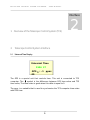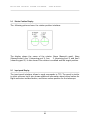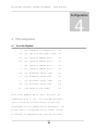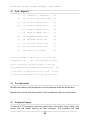
1
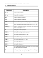
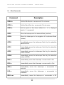
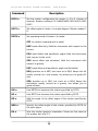
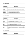
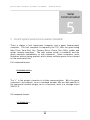
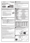
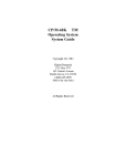
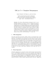
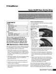
THE OBSERVATORIES OF THE CARNEGIE INSTITUTION OF WASHINGTON 813 Santa Barbara Street Pasadena, California 91101 Phone: (626) 577-1122 Fax: (626) 795-8136 TELESCOPE CONTROL SYSTEM SOFTWARE User Manual Document Code 01 - 00 - Type User Manual Author Silvia Baeza and Jose M . Soto Date April, 2012 Revision Glenn Eychaner/Felipe Sanchez Revisions Table Date Description April, 2012 Documentation of 82x EDS messages; updated documentation of rotatorrelated values. April, 2008 Document Update May 21, 2003 Document Creation Apr 29, 2012 Increase precision for M2 tilts ii Table of Contents 1 OVERVIEW OF THE TELESCOPE CONTROL SYSTEM (TCS)....................................................................1 2 TELESCOPE CONTROL SYSTEM INTERFACE.............................................................................................1 2.1 Universal Time Display........................................................................................................................................1 2.2 Focus Information Display...................................................................................................................................2 2.3 Camera Configuration Display.............................................................................................................................3 2.4 Rotator Position Display.......................................................................................................................................4 2.5 Input panel Display ..............................................................................................................................................4 2.6 Telescope Position Display..................................................................................................................................5 2.7 Serial Communication Interface...........................................................................................................................7 3 COMMANDS SUMMARY.......................................................................................................................................8 3.1 Pointing Commands.............................................................................................................................................8 3.2 Coordinate Commands.........................................................................................................................................9 3.3 Offset Commands...............................................................................................................................................10 3.4 Focus Commands...............................................................................................................................................12 3.5 Rotator Commands.............................................................................................................................................12 3.6 Dome Commands...............................................................................................................................................13 3.7 Louver Commands.............................................................................................................................................14 3.8 Other Commands................................................................................................................................................14 3.9 Message Commands...........................................................................................................................................15 3.10 Display Commands..........................................................................................................................................15 3.11 Detailed Explanation of Commands and Status Values...................................................................................16 4 TCS CONFIGURATION.......................................................................................................................................20 4.1 Tcs.ini file, Magellan I ......................................................................................................................................20 4.2 Tcs.ini , Magellan II...........................................................................................................................................21 4.3 Tcs.ini Description.............................................................................................................................................21 4.4 Starting the Program..........................................................................................................................................22 4.5 Coordinate Entry................................................................................................................................................22 4.6 Using the Trackball ...........................................................................................................................................23 4.7 Secondary Mirror Focus and Colimation ..........................................................................................................23 4.8 How to Take Data to Check or Update the Pointing Model .............................................................................24 4.9 Acknowledgement..............................................................................................................................................24 5 CONTROL SYSTEM SERIAL COMMUNICATION STANDARDS...............................................................26 5.1 Command Description........................................................................................................................................27 5.1.1 2: Query Next EDS Message......................................................................................................................28 5.1.2 3: Repeat Last EDS Message.....................................................................................................................28 5.1.3 4: Set UT.....................................................................................................................................................29 5.1.4 9: Freeform Command..............................................................................................................................30 5.2 Slaves Systems vs Tcs Control Software Communication commands............................................................31 5.2.1 Dome Control Software..............................................................................................................................31 5.2.2 Vane end Control Software........................................................................................................................33 5.2.3 Guider Control Software............................................................................................................................33 5.2.4 SiteUtil Control Software...........................................................................................................................33 5.2.5 M3 Control Software..................................................................................................................................34 5.2.6 OSS Control Software................................................................................................................................34 iii 6 LOG MESSAGE SYSTEM....................................................................................................................................35 6.1 Errors (000799).................................................................................................................................................35 6.2 EDS Log Data Format (800899).......................................................................................................................39 6.3 Successes (900999)...........................................................................................................................................41 7 TELESCOPE CONTROL SYSTEM DIFFERENCES BETWEEN MAGELLAN I AND II........................43 8 TROUBLESHOOTING..........................................................................................................................................44 iv T E L E S C O P E C O N T R O L S Y S T E M S O F T W A R E - U S E R M A N U A L - Overview Interface 1 Overview of the Telescope Control System (TCS) 2 Telescope Control System Interface 2.1 Universal Time Display 1 2 Universal Time 1536 37 GPS : -1 -39 ppm: The GPS is a special unit that controls time. This unit is connected to TCS computer. The symbol is the difference between GPS time value and TCS time value, The time value is good when this delta is equal to 0. The ppm is a variable that is used to synchronize the TCS computer time value with GPS time. 1 T E L E S C O P E 2.2 C O N T R O L S Y S T E M S O F T W A R E - U S E R Focus Information Display Z Set: 800 Ima: 32 Psn: 45 Tmp: Focus 791 Off: 0 Req: 1668 Val: 1306 X Y Set: 0 Ima: -997 Psn: -3867 -1681 Req: -4864 Val -4051 -1818 H 0 -127 -1808 V Set: 0 0 Ima: 163 Psn: 65 -98 Req: 228 -47 Val: 212 -48 51 2 M A N U A L - T E L E S C O P E C O N T R O L S Y S T E M S O F T W A R E - U S E R M A N U A L - The variables in this interface shows the actual secondary mirror position. This information is collected by Vane End Control System: Set: position value required by user Ima: focus value obtained from active optics software system Psn: variable selected from TCS configuration file. 2.3 Tmp: variable calculated by TCS. The OSS utility control system gives Tplat as an input variable for calculations. Off: offset input value. Req: is the result of adding Set+Ima+Psn+Tmp+Off Val: real position. Ca mera Configuration Display The following display shows the actual cursor position. This information is the same shown in the Guider Camera Control System Interface. For more details see "Guider Camera Control System User Manual". 3 T E L E S C O P E 2.4 C O N T R O L S Y S T E M S O F T W A R E - U S E R M A N U A L - Rotator Position Display The following picture shows the rotator position interface: The display shows the name of the rotator: Nasw (Nasmyth west), Nase (Nasmyth east), Aux 1 (observing port 1), Aux 2 (observing port 2) and Aux3 (observing port 3). It also shows if the rotator is enabled and the target position. 2.5 Input panel Display The input panel interface allows to send commands to TCS. The panel is similar to other systems, but it also shows additional information about actual values for Right ascension and declination, and future values position for the telescope. 4 T E L E S C O P E 2.6 C O N T R O L S Y S T E M S O F T W A R E - U S E R M A N U A L - Telescope Position Display Jjj Right Ascension Declination 06 21 44.69 -29 02 10.4 rtrk: 0.0000 :000.0 :00.00 roff: 0.00dut: -0.37 dtrk:0.0000 doff: 00.0 The variables are the following: Rtrk : Right ascension velocity Dtrk: Declination velocity Roff: Right ascension offset Doff: declination offset 5 T E L E S C O P E C O N T R O L S Y S T E M S O F T W A R E AZ : 000.000 Atrk: 0.000 Aoff:0.0032 - U S E R M A N U A L - EL : 00.0000 etrk: 0.0000 eoff:0.0060 Air Mass 1.000 Moon: 00z Wind: 30z Para: -39 Wrap: +046 Dome: 180 The variables meaning are the following: Atrk: Azimuth velocity Etrk: Elevation velocity Aoff: Azimuth offset Eoff: Elevation offset Air Mass Moon and Wind Para: parallactic angle Wrap: Dome: dome position 6 T E L E S C O P E 2.7 C O N T R O L S Y S T E M S O F T W A R E - U S E R M A N U A L - Serial Com munication Interface This interface shows slaves information. It shows Guest Computer address and buffer information like messages read and messages to be read. Guest Computer Address Main Drive G1 Vane end H2 OSS I3 Tertiary Mirror J4 Dome K5 Site Utility L6 Guider M7 Gcam 1 N8 Gcam 2 O9 Gcam 3 P1 The interface shows the actual configuration files read by the TCS system, these are: Tcfg variable shows the number of the TCS focus configuration file to be read. Tcfg is the point model configuration file and rcfg is the rotator configuration file number. 7 T E L E S C O P E C O N T R O L S Y S T E M S O F T W A R E - U S E R M A N U A L - Commands 3 3 Commands Summary All TCS commands begin with a command code of up to four letters, followed by up to three numeric arguments. The numeric arguments (if there are more than one) are separated by spaces; spaces are permitted but not required between the command and the first numeric argument. Letters may be upper or lower case. The numeric arguments (including zero) may be negative, and may include a decimal point. For example, the commands dc-0 25 47.2 DC -0.0 25 47.20 will both set the Dec. coordinate input to -00° 25' 47.2". The backspace key moves the cursor back one character at time. All commands are terminated by a <CR>. 3.1 Pointing Com mands Command Description MP n Set the coordinate display to show mean place for the year n. AP Set the coordinate display to show apparent place 8 T E L E S C O P E C O N T R O L S Y S T E M S O F T W A R E - U S E R M A N U A L - TP Toggle telescope pointing model on/off. TPON Set telescope pointing model on TPOF Set telescope pointing model off DUT n Enter the DUT for the current date CN n Set the camera number to mimic in the guider box to n (1-3). RS n Override the automatic setting the rotator sign for the camera specified by CN on the rotator specified by RCFG. (n = +/- 1) PF n Override the automatic setting the parity flip for the camera specified by CN on the rotator specified by RCFG. (n = +/- 1; +1 = normal, -1 = inverted) CA n Override the automatic setting guide camera position offset angle for the camera specified by CN on the rotator specified by RCFG. (n degrees) CNCA n SZ n Override the automatic setting guide camera field size for the camera specified by CN on the rotator specified by RCFG. (n arcseconds) TCFG n Read telescope config file (pointing model) n. (n = 0... 99). 9 T E L E S C O P E 3.2 C O N T R O L S Y S T E M S O F T W A R E - U S E R M A N U A L - Coordinate Com mands Command Description RA 3n Enter an RA coordinate DC 3n Enter a Dec. coordinate AZ n Enter an Azimuth coordinate EL n Enter an Elevation coordinate CAT n Save coordinate inputs in catalog entry n (n = 0... 99). OBJ n Recall coordinate inputs from catalog entry n (n = 0... 99). SLEW [n] Slew to highlighted (white) coordinate. Use alternate cable wrap angle if n = 2. H Gently halt a slew in progress RTRK n Set the RA tracking rate to n sec/sec. DTRK n Set the DEC tracking rate to n "/sec. ATRK n Set the AZ tracking rate to n °/sec. ETRK n Set the EL tracking rate to n °/sec AOFF n Set the AZ offset to n °. EOFF n Set the EL offset to n °. CSET Set the displayed equatorial coordinates to be the same as the input equatorial coordinates PT Add a pointing record (input coordinates, displayed coordinates, sidereal time) to the EDS 10 T E L E S C O P E 3.3 C O N T R O L S Y S T E M S O F T W A R E - U S E R M A N U A L - Offset Com mands Command Description OFRA n Set the RA offset to n arcseconds. Do not move OFDC n Set the Dec offset to n arcseconds. Do not move OFEP n Set the epoch of the above offsets to n. (0 = displayed epoch, -1 = apparent) OFFP Move the telescope to the above offsets (positive). OFFM Move the telescope to the negative of the above offsets (minus). OFFN Immediately move the telescope North by the absolute value of OFDC OFFS Immediately move the telescope South by the absolute value of OFDC. OFFE Immediately move the telescope East by the absolute value of OFRA. OFFW Immediately move the telescope West by the absolute value of OFRA RAG n Immediately move the telescope n arcseconds in RA. DCG n Immediately move the telescope n arcseconds in Dec. AZG n Immediately move the telescope n arcseconds in azimuth ELG n Immediately move the telescope n arcseconds in elevation RDG n m Immediately move the telescope n arcseconds in RA 11 T E L E S C O P E C O N T R O L S Y S T E M S O F T W A R E - U S E R M A N U A L - and m arcseconds in Dec AEG n m 3.4 Immediately move the telescope n arcseconds in azimuth and m arcseconds in elevation. Focus Com mands Command Description ZSET n Set the secondary focus to n microns. Also YSET, XSET HSET n Set the secondary tilt to n arcsec. Also VSET ZSTR n Set the secondary focus n microns from where it is now. (relative) Also XSTR, YSTR, HSTR, VSTR. ZIMA n Set the secondary focus image analyzer correction to n microns. Also YIMA, XIMA HIMA n Set the secondary tilt image analyzer correction to n arcsec. Also VIMA. ZIMR n Set the secondary focus image analyzer correction n microns from where it is now. (relative) Also XIMR, YIMR, HIMR, VIMR. XVIR n Set the secondary coma image analyzer corrections n microns from where they are now. (relative) Also YHIR. AUTF Auto-focus toggle on/off FCFG n Read focus config file (focus model) n. (n = 0... 99). 3.5 Rotator Com mands 12 T E L E S C O P E C O N T R O L Command S Y S T E M S O F T W A R E - U S E R M A N U A L - Description RCFG n Set the rotator configuration for rotator n, 0 to 5 (rotator of interest). Rotator numbers 0-5: NASW NASE CASS AUX1 AUX2 AUX3 ROTO n Set offset angle of rotator n to angle degrees. Rotator modes 06: ROTM n Set operating mode of rotator n to mode: OFF (no rotator command sent to vane) HRZ (send offset only) Hold the instrument with respect to the horizon EQU (send offset and parallactic angle) Hold the instrument with respect to the north GRV (send offset and elevation) Hold the instrument with respect to gravity. EQZ (send offset and parallactic angle and elevation) HEQ (position as in HRZ, but track as in EQU) Keeps the slit mostly vertical w.r.t the horizon, but allows you to guide offaxis. GEQ (position as in GRV, but track as in EQU) Keeps the instrument mostly vertical w.r.t gravity, but allows you to guide off-axis. RM n Like ROTM but assumes the rotator specified by RCFG RO n Like ROTO but assumes the rotator specified by RCFG DR n Add the angle to the offset angle of the rotator specified by RCFG NRO n Specify the offset angle of the rotator specified by RCFG for the next object. RV n Sets the rotator graphics orientation. Views are the same as the modes, but only 0-3. 13 T E L E S C O P E 3.6 C O N T R O L S Y S T E M S O F T W A R E - U S E R M A N U A L - Dome Com mands Command Description DOME n Move dome to azimuth angle n. AUTD Automatic dome position toggle on/off. Use when tracking. WIND n Set the windscreen extension to n percent MOON n Set the moonscreen extension to n percent 3.7 Louver Com mands Command Description FL n m Set fixed louver n to opening m (m = 0... 4). RL n m Set rotating louver pair n to opening m (m = 0... 4). AFL n Set all fixed louvers to opening n (n = 0... 4). ARL n Set all rotating louvers to opening n (n = 0... 4). HFL n Disable (hold) / enable commands for fixed louver n (toggle). HRL n Disable (hold) / enable commands for rotating louver pair n (toggle). 3.8 Other Com mands Command Description 14 T E L E S C O P E C O N T R O L S Y S T E M S O F T W A R E - U S E R M A N U A L - SM Simulated coordinates toggle on/off (for diagnostics only). SAVE Save most of the data on the screen, including the catalog. Please read the explanation in the text. VERB n m Set report mask for device n to level m. REM n Set remote serial unit to device n. LINK Toggle operator enable/disable of TCP/IP uplink. EXIT Exit from the program 3.9 Message Com mands Command Description <Up> Scroll system message display back one line. <Pg Up> Scroll system message display back one page <Down> Scroll system message display forward one line <Pg Dn> Scroll system message display forward one page <Home> Set system message display to show the first message <End> Set system message display to show the current message 3.10 Display Com mands 15 T E L E S C O P E C O N T R O L S Y S T E M S O F T W A R E Command - U S E R M A N U A L - Description <Scroll Lock> Pause/Resume system log messages VERB n Set system log verbose level to n (n = 0 … 2) 3.11 Detailed Explanation of Com mands and Status Values MP: Set the coordinate display to show mean place coordinates for a given year by using the MP command. The coordinate system is the FK5 (IAU 1976) system (e.g. J2000.), which is very slightly different from the FK4 (e.g. B1950.) system. However, the difference between the two systems (for example between J1950. and B1950.) is negligible. The coordinate system in use is shown just above the green RA and Dec. display. AP: Type "AP" to set the coordinate display to show apparent place. Apparent place includes the effect of nutation (amplitude 10 arcsec) and aberration (amplitude 20 arcsec), so apparent place coordinates are NOT the same as mean place coordinates for the time of observation. TP: The displayed coordinates will be corrected according to the telescope pointing model when TP is enabled. A green "TP" message will appear in the coordinate input box. The TP command is a toggle which will alternately turn the pointing model off or on. DUT: The UT derived from the GPS system is UTC, with seconds of constant length derived from atomic time. The telescope really needs UT1, which is true solar time with seconds that vary slightly in length depending on variations in the rotation of the earth. The correction UT1 - UTC (up to 1 second of time) is entered using the command DUT. The correction can be found at the web site for the International Earth Rotation Service ( http://maia.usno.navy.mil/eo/eo_home.html ). Failure to enter the DUT will result in pointing errors of up to 15 arcseconds. RS, PF, CA, SZ: In order to use the mouse to guide the telescope, you need to enter the position angle of the camera using the CA command. You also need to enter the size of the camera field using the SZ command. These are normally entered automatically by the CN and RCFG commands. 16 T E L E S C O P E C O N T R O L S Y S T E M S O F T W A R E - U S E R M A N U A L - TCFG: Different pointing models are stored in the files TCFG.nn (nn = 00... 99). There are different pointing models for different focal stations, for example. In order to change pointing models, use the TCFG command to read in a different file. You will get a non-threatening error message if the file doesn’t exist, and the old model will be left intact. RA, DC: Enter equatorial coordinates using the RA and DC commands. The coordinates will appear in the coordinate input box. The RA and Dec. values will be highlighted (white), and the derived Az and El will be shown in black. For some positions, two alternate azimuth cable wrap angles (separated by 360°) will be shown at the “Wrap1” and “Wrap2” locations. AZ, EL: Enter Az-El coordinates using the AZ and EL commands. The coordinates will appear in the coordinate input box. The Az and El values will be highlighted (white), and the derived RA and Dec. will be shown in black. . For some positions, two alternate azimuth cable wrap angles (separated by 360°) will be shown at the “Wrap1” and “Wrap2” locations. SLEW: When you are sure the coordinate inputs are the ones you want, slew the telescope using the SLEW command. If the highlighted inputs are Az and El, the telescope will go to the coordinates and stop. If the highlighted inputs are RA and Dec, the telescope will go to the coordinates and track at the sidereal rate. H: A slew can take more than two minutes. If you realize you have made a mistake, type H. The telescope will come to a controlled stop, and you can try again. RTRK: Once the telescope is slewed to an equatorial coordinate, you can adjust the tracking rates (relative to sidereal) using the RTRK and DTRK commands. “RTRK 1” for example, will stop the telescope. “RTRK -1” will track at twice the sidereal rate. DTRK, ATRK and ETRK are similar. CAT: The program can store coordinate input values in a catalog with entries numbered from 0 to 99. To store coordinates in entry n, type "CAT n". OBJ: Once you have stored a set of coordinates in catalog entry n, you can quickly bring them back by typing "OBJ n". ZSET: Enter the focus value with the command ZSET. If auto-focus is enabled, the secondary will move to the position derived from this value automatically. The YSET, XSET, HSET and VSET commands are similar. 17 T E L E S C O P E C O N T R O L S Y S T E M S O F T W A R E - U S E R M A N U A L - AUTF: Toggle the auto-focus function on and off with the command AUTF. It is OK to leave the auto-focus function enabled when slewing the telescope. FCFG: There are up to 100 different models for the focus adjustment, stored in files FCFG.nn (nn = 00… 99). In order to change focus models, use the FCFG command to read a different file. If the file doesn’t exist, a non-threatening message will appear, and the previous model will be left intact. The number of the current model is displayed in the status box at the fcfg: entry. DOME: The dome can be manually moved to a given azimuth by entering the DOME command, followed by the azimuth angle. Once the dome is moving, pressing the <esc> key should bring it to an immediate, gentle stop. (The <esc> function may not be implemented in the current version of the software). AUTD: The dome will track the telescope automatically when the AUTD function is toggled on. WIND: (also MOON:) The windscreen and moonroof can be moved using the commands WIND and MOON. There is no automatic function for the windscreen and moonroof positions. However, the diagram displayed on the screen is dimensionally accurate and can be used to judge whether the windscreen and moonroof clear the optical path of the telescope. FL, RL: You can adjust a single louver on the fixed part of the enclosure, or a single pair of louvers on the rotating dome, using the FL or RL command. The arguments are the louver number and the opening in fourths. The numbering scheme of the fixed and rotating louvers is displayed in the on-screen diagram, which also shows the true azimuth orientation of the telescope and the dome. When the louvers are moving, the corresponding frame in the diagram will turn yellow. If a louver control error occurs, the corresponding frame will turn red. As the louvers open, the frame will be shaded black, one-fourth of the area at a time. The frame will turn white if a louver has been temporarily disabled using the HFL or HRL toggle commands. AFL: (also RFL:) You can adjust all of the fixed louvers or all of the rotating louvers with the AFL and RFL commands. HFL: (also HRL:) A single fixed louver or rotating louver pair can be taken offline using the HFL (hold fixed louver) or HRL (hold rotating louver) commands. When a louver is off-line, it will not respond to the commands FL, RL, AFL or ARL. The color of the corresponding frame in the diagram will change to white. Repeat the HFL or HRL command to return a given louver to the on-line condition. 18 T E L E S C O P E C O N T R O L S Y S T E M S O F T W A R E - U S E R M A N U A L - SM: For testing only, the coordinate inputs can be used to simulate a set of telescope coordinates using the SM command. A red "SM" message will appear in the coordinate input box. Type SM again to turn off simulated coordinates. There is another, better way to simulate coordinates. Leave the TCS in the normal condition (SM off). Make certain that the main drives are completely disabled (for example by hitting the <Esc> key on the main drive computer). Now enter only the PS command on the main drive computer. This will enable the azimuth and elevation position profilers while leaving the actual drives and hydrostatic pads completely disabled. Most importantly, the normal main drive position servo error-checking will also be disabled. (Normally the error-checking will issue a panic shutdown if the position error is greater that .002°.) The main drive position profilers will then report the profiler position to the TCS exactly as if the telescope were really moving. The fact that the position servo errors will rise to many degrees will be ignored. There is only one dangerous condition which can be encounterd when simulating coordinates in this way (using the main drive computer). If the instrument rotators are enabled, they will move as if the mount were actually moving, when in fact the mount will not move. It may also be necessary to disable the instrument rotators in order to guarantee the safety of instruments mounted on them. SAVE: Most of the operator-selected parameters of the TCS program can be saved to disk at any time using the SAVE command. The saved parameters include the display epoch, choice of config files for pointing, focus and rotator models, and the catalog of objects. If you have to re-boot the computer for any reason, the program will come back with the same choice of parameters that was in effect at the time of the last SAVE command. VERB: The low-level control computers report a constant stream of information to the TCS. Normally this information is not displayed in the TCS system message box. This corresponds to VERB level 0 for each control computer. The low level computers are assigned index numbers which are shown in the status box (Main Drive – 1, Vane End – 2, etc.). Changing VERB level to 1 for a given computer will display error messages from that computer in the TCS message box. Changing VERB level to 2 for a given computer will display all engineering data stream (EDS) messages from that computer in the TCS message box. The number of messages received per second from each low-level computer is displayed in the status box as the first of two numbers. The messages are buffered in the low-level computers and transmitted over serial links as time allows. The second number is the maximum number of messages waiting to be transmitted in a given second of time. 19 T E L E S C O P E C O N T R O L S Y S T E M S O F T W A R E - U S E R M A N U A L - REM: There is a serial port on the TCS which will transmit all of the EDS messages from a given low-level computer to a remote program which can reconstruct the low-level display screen at a remote location. The remote program can also accept commands which are relayed through the TCS to the actual low-level control computer. The remote port can be switched from one low-level computer to another with the REM command. LINK: This will toggle the operator enable/disable of the TCP/IP uplink. If while enabled, the link is broken, the TCS will try to restore the link every 5 minutes. If you want to try to restore the link before then, toggle LINK off/on. EXIT: To exit from the program, type "EXIT". 20 T E L E S C O P E C O N T R O L S Y S T E M S O F T W A R E - U S E R M A N U A L - Configuration 4 4 TCS Configuration 4.1 Tcs.ini file, Magellan I 1 ;(1) 1=Magellan 1, 2=Magellan 2 i*4 36 ;(2) Cpu clock rate (ppm), +=fast i*4 192 ;(3) Uplink IP address byte 1 i*4 168 ;(4) Uplink IP address byte 2 i*4 0 ;(5) Uplink IP address byte 3 i*4 1 ;(6) Uplink IP address byte 4 i*4 291 ;(7) Windscreen retract limit i*4 500 ;(8) Windscreen extend limit i*4 100 ;(9) Moonscreen retract limit i*4 789 ;(10) Moonscreen extend limit i*4 5600 ;(11) Uplink IP port number i*4 ; ;This is the Magellan TCS ini file. The lines are ;numbered from (1) to (11). All lines MUST be present. ;The ini values are the first entries on each line, ;followed by the line numbers and the description. Use ;a text editor to change ONLY the ini values. Be sure ;to maintain the appropriate data type for each entry. ; 21 T E L E S C O P E 4.2 C O N T R O L S Y S T E M S O F T W A R E - U S E R M A N U A L - Tcs.ini , Magellan II 2 ;(1) 1=Magellan 1, 2=Magellan 2 i*4 36 ;(2) Cpu clock rate (ppm), +=fast i*4 192 ;(3) Uplink IP address byte 1 i*4 168 ;(4) Uplink IP address byte 2 i*4 0 ;(5) Uplink IP address byte 3 i*4 1 ;(6) Uplink IP address byte 4 i*4 291 ;(7) Windscreen retract limit i*4 960 ;(8) Windscreen extend limit i*4 100 ;(9) Moonscreen retract limit i*4 789 ;(10) Moonscreen extend limit i*4 5600 ;(11) Uplink IP port number i*4 ; ;This is the Magellan TCS ini file. The lines are ;numbered from (1) to (11). All lines MUST be present. ;The ini values are the first entries on each line, ;followed by the line numbers and the description. Use ;a text editor to change ONLY the ini values. Be sure ;to maintain the appropriate data type for each entry. ; 4.3 Tcs.ini Description WindScreen retract and extend limit: are the software limits for windscreen MoonScreen retract and extend limit:: are the software limits for moonscreen 4.4 Starting the Program To start the TCS program, push the reset button (the black rocker switch just below the red power switch) on the computer. The program will load 22 T E L E S C O P E C O N T R O L S Y S T E M S O F T W A R E - U S E R M A N U A L - automatically from the solid-state disk. Resetting the computer assures that the system will start each time in the proper state. Note that the UT date is initialized from the internal computer clock, which MUST be set to the correct UT date and UT time. If the date is wrong, then the displayed sidereal time will be off by at least four minutes. To reset the date, check the CMOS setup of the PC. Enter the CMOS setup routine by pressing <del> on the keyboard a few seconds after pressing the reset button. 4.5 Coordinate Entry In order to slew the telescope, the desired coordinates must first be entered into the coordinate input box. The telescope will not move until the SLEW command is entered. The coordinate input box displays both Az-El and equatorial coordinates. If an azimuth or an elevation angle has been entered most recently, the Az and El coordinates will be highlighted in white, and the TCS will calculate the corresponding RA and Dec (as a function of time) and display them in black. If an RA or Dec coordinate has been entered most recently, the RA and Dec coordinates will be highlighted in white, and the TCS will calculate the corresponding azimuth and elevation angles (as a function of time) and display them in black. The telescope will not slew to an elevation angle below 10°, or to an equatorial coordinate within 0.4° of the zenith. If either of these conditions occur, the value of the elevation angle will be shown in red. The epoch of the equatorial coordinates in the coordinate input box is the same as the epoch of the equatorial coordinates of the main telescope coordinate display. The coordinate inputs are also displayed as the red pointers in the equatorial coordinate dials and in the azimuth and elevation diagrams. The current position of the telescope is displayed as the black pointers in the equatorial dials, and as the U-shaped figures (drawn approximately to scale) in the azimuth and elevation diagrams. The telescope will slew to the desired coordinates when the SLEW command is entered. If Az-El coordinates have been entered, the telescope will move to the desired coordinate and then stop. If equatorial coordinates have been entered, the telescope will slew to the desired coordinates and then track at the sidereal rate. 23 T E L E S C O P E 4.6 C O N T R O L S Y S T E M S O F T W A R E - U S E R M A N U A L - Using the Trackball Small adjustments to the telescope position can be made using the trackball. Moving the trackball moves a red pointer in the small rectangular diagram on the TCS display. The diagram is intended to represent the field of the TV viewer. The TCS must be informed about the size and orientation of the TV display using the SZ, RS, PF and CA commands. These are usually set automatically by the RCFG and CN commands, but may be overridden by the operator for testing. The trackball will also move xy1 on the guide cameras. Also, in the small rectangular diagram, you will see two colored L-shaped marks. The red one in the upper left shows the orientation of the elevation and azimuth axes. The longer arm shows the +elevation direction and the shorter arm shows the +azimuth direction. The green one in the upper right shows the orientation of the declination and right ascension axes. The longer arm shows the north direction and the shorter arm shows the east direction. To move a given object in the TV field to the center of the square box, move the trackball pointer to the position in the diagram which corresponds to the position of the object in the TV field. Then press the right button on the trackball and click the left button. The telescope will move so that the object appears in the center of the square box. If you click the left button without pressing the right button, the object will move only one-tenth of the distance to the center of the square box. You can introduce small guiding motions by moving the pointer close to the center of the square box, and clicking just the left button. The square box follows the position of the guide box (xy5) on the guide camera specified by CN. 4.7 Secondary Mirror Focus and Colimation The vane-end actuators control 5 degrees of freedom of the secondary mirror: focus (Z), collimation (X, Y), and tip/tilt (H, V). The TCS computer will send commands to the vane-end system to automatically maintain focus, collimation and tip/tilt as the telescope moves in elevation, according to the particular focus model which is loaded with the command FCFG. The actual value for each of the 5 adjustments is derived from the sum of several parameters which are shown in the focus box on the TCS display. Each adjustment has a nominal set point which is the value with the telescope pointing to the zenith (set:). To this value is added the cumulative magnitude of any adjustments requested by the image analyzer (ima:), and the value of the flexure term at the current position (psn:), as derived from the focus model. The focus adjustment is particularly sensitive and includes an additional correction for temperature (tmp:), as well as an offset term which allows a correction to be introduced manually, for example to 24 T E L E S C O P E C O N T R O L S Y S T E M S O F T W A R E - U S E R M A N U A L - compensate for the focus change for different filters in a direct camera (off:). The temperature correction is zero at a nominal temperature of 12° The derived setpoint for each of the 5 adjustments is shown as the requested (req:) value. For comparison, the actual position of the vane-end assembly is also shown (val:). If the automatic focus function is switched on using the AUTF toggle, the vane-end assembly will constantly seek to the requested values. 4.8 How to Take Data to Check or Update the Pointing Model A good check of the pointing model requires 30-50 observations, and a good set of data for deriving a new pointing model requires 100 or so. Each setting will require about 2 minutes, so the best thing to do is to get organized in a systematic way. Plan to start an hour or two late, so that the telescope will have time to come to thermal equilibrium after the dome is opened. While you are waiting (or during the afternoon), choose a set of stars from the SAO catalog or the Astronomical Almanac. Pick a set of stars at approximately the same RA which will place them about 4.5 hours east when you begin, and spaced in declination by about 15 degrees between +35 and -85. Pick another set which will be on the meridian at the beginning of the night, spaced in declination in the same way. Finally, pick 3 or 4 stars which are 1 hour further east than the first set, between -40 and -85, and 3 or 4 stars which are 1 hour further west than the second set, between -40 and -85. Number the stars in order of declination within each set (keeping separate the extras which are 1 hour over), and make a list with their catalog positions and proper motions. Now observe the 3 or 4 stars which are furthest east. When each star is centered on the crosshairs, record the RA and Dec. coordinates with TP turned off, and the sidereal time (which is used to derive the hour angle). Next observe the east star list, working from the pole to the equator, and then the meridian star list, working from the equator to the pole. Repeat the two lists as the night goes by, but don't repeat the 3 or 4 which are furthest east. Gradually the east list will end up on the meridian, and the meridian list will end up 4.5 hours west. After half a night, do the 3 or 4 stars which are furthest west (again only once), and then you are done. Of course the stars which are furthest north in each list will not be accessible at extreme hour angles. You only need to do these when it makes sense. 25 T E L E S C O P E 4.9 C O N T R O L S Y S T E M S O F T W A R E - U S E R M A N U A L - Acknowledgement The TCS program makes extensive use of the SLALIB and TPOINT program libraries, which were developed and graciously provided by Pat Wallace of STARLINK. 26 T E L E S C O P E C O N T R O L S Y S T E M S O F T W A R E - U S E R M A N U A L - Serial Communication 5 5 Control System Serial Communication Standards There is always a host (upstream) computer, and a guest (downstream) computer. The host computer is frequently the TCS, with the guest being Main Drive, Vane End, Oss, Tertiary Mirror, Dome, Site Utility, guider and guider camera computers. The host system sends a command, and the guest responds immediately to that command. Guest computers never broadcast without being queried, which allows multiple guests to be chained on the same serial line. Full command format: :Nnddddddddddccr The “:” is the prompt character to initiate communication. N is the guest computer’s unit address. n is a command number, d’s are data specific to the command (variable length), cc is a checksum, and r is a carriage return (ASCII 13). Full response format: ~Nndddddddccr 27 T E L E S C O P E C O N T R O L S Y S T E M S O F T W A R E - U S E R M A N U A L - The “~” is the response character for guest computer responses. N is the guest computer’s unit address. n is the command number this is in response to, d’s are data specific to the response (variable length), cc is a checksum, and r is a carriage return (ASCII 13). For very short commands and responses the checksum may be omitted (this is noted in the command description). For all commands and responses that include a checksum, the checksum is composed of two hexadecimal digits (from 0-F). The checksum is calculated by starting with zero and XORing it with all characters in the message from the unit letter to the last data character before the checksum (the underlined part of the command and response above). Commands that are received but misunderstood (checksum wrong, unknown command, etc) are replied to like this: ~N?r Most guest computers maintain a running system log that contains important messages and all system status information. Each also maintains a pointer into that log that keeps track of the oldest message that hasn’t been sent to the host computer. The “2” and “3” commands let the host computer command the guest computer to transmit one of its log entries or re-transmit the last entry. This is referred to as the “Engineering Data Stream”, or EDS. Command Summary: 2: Query Next EDS Message 3: Repeat Last EDS Message 4: Set UT 9: Free-form Command 5.1 5.1.1 Com mand Description 2: Query Next EDS Message 28 T E L E S C O P E C O N T R O L S Y S T E M S O F T W A R E - U S E R M A N U A L - Commands the guest computer to send its oldest un-sent EDS log entry, and advance its internal pointer to the next EDS log entry. Command Format: :N2r (note that this command has no checksum) Response Format: ~N2qqnnttttttttfffdddddddccr N Guest computer address (usually an upper-case letter) qq Two-digit number of EDS messages left in the guest queue nn Two-digit number of characters in the message (in the underlined section). 00 if no message available tttttttt Eight-digit message time stamp (no punctuation), with twodigit hour, two-digit minute, two-digit second, and two-digit hundredths of a second. fff Three-digit message number. Message numbers from 0-799 denote errors, 800-899 are numberical data formats, and 900999 are successes ddddddd Variable length message data section. For error and success messages, typically a simple text message. For numeric data formats, a combination of ASCII, decimal, and hexadecimal characters/digits, with the format being determined by the particular message number cc Checksum, described above. r ASCII charater 13, a carriage return. 5.1.2 3: Repeat Last EDS Message Commands the guest computer to re-send the last message it sent (implying that the host computer had a serial communication error during the last reponse). The guest’s internal pointer should remain unchanged. Command Format: :N3r (note that this command has no checksum) Response Format: ~N3qqnnttttttttfffdddddddccr 29 T E L E S C O P E C O N T R O L S Y S T E M S O F T W A R E - U S E R M A N U A L - N Guest computer address (usually an upper-case letter) qq Two-digit number of EDS messages left in the guest queue nn Two-digit number of characters in the message (in the underlined section). 00 if no message available (there is no time stamp, message number, or data in this case). tttttttt Eight-digit message time stamp (no punctuation), with twodigit hour, two-digit minute, two-digit second, and two-digit hundredths of a second. fff Three-digit message number. Message numbers from 0-799 denote errors, 800-899 are numberical data formats, and 900-999 are successes. ddddddd Variable length message data section. For error and success messages, typically a simple text message. For numeric data formats, a combination of ASCII, decimal, and hexadecimal characters/digits, with the format being determined by the particular message number. cc Checksum, described above. r ASCII charater 13, a carriage return. 5.1.3 4: Set UT Commands the guest computer to set its clock to the Universal Time given in this command. The control computers keep their clocks synchronized to GPS-provided universal time in this way. Command Format: :N4ttttttttccr Response Format: ~N4er (note that this response has no checksum) N Guest computer address (usually an upper-case letter) tttttttt Eight-digit universal time (no punctuation), with two-digit hour, two-digit minute, two-digit second, and two-digit 30 T E L E S C O P E C O N T R O L S Y S T E M S O F T W A R E - U S E R M A N U A L - hundredths of a second. cc Checksum, described above. r ASCII charater 13, a carriage return. e Error flag: 0 if an error occurred, 1 if OK. 5.1.4 9: Free-form Command Sends the guest computer a free-form command, typically similar to the commands entered via the guest computer’s keyboard. This is used to command moves, homes, etc. Command Format: :N9nndddddddccr Response Format: ~N9ennmmmmccr N Guest computer address (usually an upper-case letter) nn Two-digit number of characters in the message (in the underlined section). 00 if no message available. ddddddd Variable length free-form command section. This section will contain a command parseable by the guest computer, such as “MOVE 1000” cc Checksum, described above. r ASCII charater 13, a carriage return. e Error flag: 0 if OK, 1 or higher if an error occurred mmmm Variable length diagnostic message (such as “Move ignored, brake on”). This should be printed out by the host computer in the command input box if the command was given by the user, or in the system log if the command was given by an automated routine in the host program. nn=00 in the response if there is no diagnostic 31 T E L E S C O P E C O N T R O L S Y S T E M S O F T W A R E - U S E R M A N U A L - message. 5.2 Slaves Systems vs Tcs Control Software Com munication com mands There are another commands format and response from slaves systems that allows TCS system to send command request . The slaves systems always sent an answer showing the results of command execution. Remember that almost all jobs are done by slaves. TCS manages their slaves using the following communication protocol. 5.2.1 Dome Control Software 8: TELESCOPE ELEVATION INFORMATION TCS control software sends telescope elevation information every 30 seconds. This information is used to move windscreen and moonscreen. Command Format: :K8nnnnnnccr Response Format: ~K8fr K Dome computer address (usually an upper-case letter) 8 This number indicates to dome control software that information sent is about telescope elevation information. nnnnnn This is the elevation value. f Is the reply flag sent to TCS control software. If f =1 then the elevation value was read by dome software without problems. If f = 0 the elevation information was not received in perfect condition (checksum is bad, command sent by Tcs is corrupted, etc). cc Checksum, described above. 32 T E L E S C O P E r C O N T R O L S Y S T E M S O F T W A R E - U S E R M A N U A L - ASCII charater 13, a carriage return. 5: DOME POSITION TCS control software sends new dome position. Command Format: :K5ppppeeeftccr Response Format: ~K5mr K Dome computer address (usually an upper-case letter) 5 This number indicates to dome control software that information sent is about new position that dome control software should execute. pppp This is the elevation value. eee Position error. f Flag: 1, 2, 3, or 5, 6, 7. t number of position iterations m Is the reply flag sent to TCS control software. If f =1 then the dome position command was accepted. If f = 0 the information was not received in perfect condition (checksum is bad, command sent by Tcs is corrupted, etc). If f = 2, command is ignored (another motion was executed). cc Checksum, described above. r ASCII charater 13, a carriage return. 1: LOUVER COMMANDS Tcs control software sends a complete command sequence for 18 louvers, positions from 1 to 10 for rotating louvers, and positions from 11 to 18 for 33 T E L E S C O P E C O N T R O L S Y S T E M S O F T W A R E - U S E R M A N U A L - fixed louvers. If there is no new louver motion, the Tcs control software don’t sent any louver command sequence. Command Format: :K1aaaaaaaaaaaaaaaaaaccr Response Format: ~K1mr K Dome computer address (usually an upper-case letter) 1 This number indicates to dome control software that information sent is about telescope louvers information. aaaaaaaaaaaaa aaaaa All louvers commands f Reply flag sent to TCS control software. If f =1 then the louver command was read by dome software without problems. If f = 0, information was not received in perfect condition (checksum is bad, command sent by Tcs is corrupted, etc). cc Checksum, described above. r ASCII charater 13, a carriage return. 5.2.2 Vane end Control Software 5.2.3 Guider Control Software 5.2.4 SiteUtil Control Software 5.2.5 M3 Control Software 34 T E L E S C O P E 5.2.6 C O N T R O L S Y S T E M S O F T W A R E OSS Control Software 35 - U S E R M A N U A L - T E L E S C O P E C O N T R O L S Y S T E M S O F T W A R E - U S E R M A N U A L - Log Message System 6 6 Log Message System This is a numerical index of all error messages from the Magellan telescope control program. 6.1 Errors (000799) 000: DOS date error, code = XXX 001: Louver command data error 002: Louver command com error X 003: Louver message length error 004: Dome UT set data error 005: Dome UT set com error X 007: Dome EDS length error 008: Dome EDS data error 009: Dome EDS com error X 010: Dome error messages suspended 011: Left louver EDS length err 012: Right louver EDS length err 013: Fixed louver EDS length err 014: Dome drive EDS length error 015: Dome position data error 016: Dome position com error X 36 T E L E S C O P E C O N T R O L S Y S T E M S O F T W A R E - U S E R 017: UPLC EDS length error 018: Moonscr/Windscr data error 019: Moonscr/Windscr com error X 020: Elevation zenith limit 021: Elevation horizon limit 022: Sidereal tracking zenith limit" 023: Servo error: slew aborted 024: Slew aborted 026: Az rate exceeded near zenith 027: Lift/Hatch EDS length err 030: Main Drive error msgs suspended 031: Main Drive UT set data error 032: Main Drive UT set com error X 033: Main Drive position decode error 034: Main Drive position data error 035: Main Drive position com error X 036: Main Drive EDS data error 037: Main Drive EDS com error X 038: Main Drive velocity cmd rejected 039: Main Drive vel cmd data error 040: Main Drive vel cmd com error X 041: Main Drv jog cmd transmit error 042: Main Drive jog command rejected 043: Main Drive jog cmd data error 044: Main Drive jog cmd com error X 045: Main Drive continue cmd rejected 046: Main Drive continue cmd data err 047: Main Drv continue cmd com err X 37 M A N U A L - T E L E S C O P E C O N T R O L S Y S T E M S O F T W A R E 048: Main Drive stop command data err 049: Main Drive stop cmd com error X 050: Motion stopped by operator 051: Main drive EDS length error 060: GPS serial com error X 061: GPS message length error 062: GPS time stamp error 063: GPS consistency error 064: GPS error messages suspended 070: Vane End error msgs suspended 071: Vane End UT set data error 072: Vane End UT set com error X 073: Vane End rem cmd com error X 074: Vane End rem cmd data error XX 075: Vane End global cmd function err 076: Vane End EDS data error XX 077: Vane End EDS com error X 078: Vane End global cmd check error 079: Vane End global cmd reply error 080: Vane End global cmd com error X 081: Vane End EDS length error 082: Vane Global EDS length error 083: Reply = 093: Remote error messages suspended 094: Remote command checksum error 095: Unrecognized remote command 096: Remote command length error 097: Remote command timeout 38 - U S E R M A N U A L - T E L E S C O P E C O N T R O L S Y S T E M S O F T W A R E - U S E R 101: TCP Open Socket failure 102: TCP connection timeout 103: TCP write socket error XXX YYY 104: TCP connection broken 105: TCP error messages suspended 110: Site Util error msgs suspended 111: Site Util UT set data error 112: Site Util UT set com error X 113: Site Util rem cmd com error X 114: Site Util rem cmd data error XX 116: Site Util EDS data error XX 117: Site Util EDS com error X 121: Site Util EDS length error 130: OSS Util error msgs suspended 131: OSS Util UT set data error 132: OSS Util UT set com error X 133: OSS Util rem cmd com error X 134: OSS Util rem cmd data error XX 136: OSS Util EDS data error XX 137: OSS Util EDS com error X 141: OSS Util EDS length error 142: OSS temperature EDS length error 151: Focus config error at line XX 155: Telescope config err at line XX 156: Number of gterms exceeded 157: Number of sterms exceeded 39 M A N U A L - T E L E S C O P E 6.2 C O N T R O L S Y S T E M S O F T W A R E - U S E R M A N U A L - EDS Log Data Format (800899) 801: Information about observation date Format: 801yyyymmdd hh ii ss HH II SS aaaaaaaaaabbbbbbbbbbccccccc yyyy-mm-dd: Observation date hh ii ss: UT HH II SS: ST aaaaaaaaaa: Right ascension bbbbbbbbbb:Declination ccccccc: Epoch 802: Information about Telescope position Format: 802aaaaaaaaaabbbbbbbbbccccccccmmmmmmxvvvvvvvvvyzuuuuuum aaaaaaaaaa: ha bbbbbbbbb:Azimuth cccccccc: Elevation mmmmmm: Airmass x: Rotator of interest vvvvvvvvv: Rotator encoder plus/minus parallactic angle, depending on rotator1 y: Slew flag z: Track flag uuuuuu: Current focus in user coordinates m: Rotator servo flag 803: Tcs coordinates inputs in control program Format: 803aaaaaaaaaaabbbbbbbbbbbcccccccccccdddddddddddeeeeeeee aaaaaaaaaaa: Telescope right ascension (telra) (pointing tests) 1 Equivalent to the rotator offset in rotator mode 2 (EQU), the normal operating mode of the rotator. 40 T E L E S C O P E C O N T R O L S Y S T E M S O F T W A R E - U S E R M A N U A L - bbbbbbbbbbb: Telescope declination (teldc) ccccccccccc: inpra (input right ascension) ddddddddddd: inpdc (input declination) eeeeeeee: st 804: Coordinates inputs in control program Format: 804aaaaaaaaaaabbbbbbbbbbbzzzzzzzzzffffffffhhhhhhhh aaaaaaaaaaa: inpra bbbbbbbbbbb: inpdc zzzzzzzzz: inpaz (input azimuth) hhhhhhhh: inpel (input elevation) 805: Information about Vane end status program for TCS Format: 805dddddddddaaaaaaaaabbbbbbbbbpppppppppzzzzzzzzzttttttttt ddddddddd: dome azimuth aaaaaaaaa: rotpos (rotator encoder angle of input coordinates) bbbbbbbbb: inppad (parallactic angle of input coordinates) ppppppppp: rotpa (parallactic angle of current target) zzzzzzzzz: rotpah (parallactic angle of target in one hour) ttttttttt: rotofh (current rotator offset, except in rotator modes 5 and 6) 806: Instrument rotator information Format: 806aaaaaaaaabbbbbbbbbcccccccccfffffffffggggggggghhhhhhhhh aaaaaaaaa: gangle (rotator gravity angle for current view mode) bbbbbbbbb: hangle (rotator horizon angle for current view mode) ccccccccc: eangle (rotator encoder angle for current view mode) fffffffff: pangle (rotator encoder angle of input coordinates for current view mode) ggggggggg: fangle (rotator encoder angle in one hour for current view mode) 41 T E L E S C O P E C O N T R O L S Y S T E M S O F T W A R E - U S E R M A N U A L - hhhhhhhhh: nangle (parallactic angle for current view mode) 807: Main Drive velocity commands Format: 807aaaaaaaaabbbbbbbbb aaaaaaaaa: 1.d8 * (azpv + 5.d0) degrees/second bbbbbbbbb: 1.d8 * (elpv + 5.d0) 808: Main Drive jog commands Format: 808aaaaaaaaabbbbbbbbb aaaaaaaaa: 1.d6 * (azpj + 500.d0) degrees bbbbbbbbb: 1.d6 * (elpj + 500.d0) 809: Camera angles information Format: 809aaaabbbbdddd aaaa: camera angle 1 bbbb: camera angle 2 dddd: camera angle 3 820: Z axis M2 position information Format: 815aaaaaabbbbbbccccccddddddeeeeeeffffffgggggg aaaaaa: Z set bbbbbb: Z ima cccccc: Z psn dddddd: Z tmp eeeeee: Z off ffffff: Z req gggggg: Z val 821: Y axis M2 position information Format: 816aaaaaabbbbbbccccccddddddeeeeee aaaaaa: Y set bbbbbb: Y ima 42 T E L E S C O P E C O N T R O L S Y S T E M S O F T W A R E - U S E R M A N U A L - cccccc: Y psn dddddd: Y req eeeeee: Y val 822: X axis M2 position information Format: 817aaaaaabbbbbbccccccddddddeeeeee aaaaaa: X set bbbbbb: X ima cccccc: X psn dddddd: X req eeeeee: X val 823: H axis M2 position information Format: 818aaaaaaaaabbbbbbbbbcccccccccdddddddddeeeeeeeee aaaaaaaaa: H set bbbbbbbbb: H ima ccccccccc: H psn ddddddddd: H req eeeeeeeee: H val 824: V axis M2 position information Format: 819aaaaaaaaabbbbbbbbbcccccccccdddddddddeeeeeeeee aaaaaaaaa: V set bbbbbbbbb: V ima ccccccccc: V psn ddddddddd: V req eeeeeeeee: V val 6.3 Successes (900999) 966; ffffffff nnnnnnnn vvvvvvvvvvv 43 T E L E S C O P E C O N T R O L S Y S T E M S O F T W A R E 967; nnn vvvvvvvvvvv 968; (title) 969; Reading config file tcfg.nn 972; Remote error messages resumed 973; OSS Util error msgs resumed 974; Site Util error msgs resumed 979; TCP error messages resumed 980; TCP socket opened 981; Slew complete 982; Slew complete: t = xxx.x sec 984; Slew hh mm ss.ss ddd mm ss.s 985; Estimated slew time xxx.x sec ;x 986; Slew xxx.xxxx xx.xxxx (xxxx) 988; Sim. aaa.aaaa ee.eeee 989; Sim. hh mm ss.ss ddd mm ss.ss 990; TCP connection established 991; TCP buffer size = XXXX 992; TCP buffer address = XXXXXX 993; Remote error messages resumed 994; Vane End error msgs resumed 995; UT set by GPS to HH MM SS.00 996; GPS error messages resumed 997; Main Drive error msgs resumed 998; MGTCS initialization complete 999; Dome error messages resumed 44 - U S E R M A N U A L - T E L E S C O P E C O N T R O L S Y S T E M S O F T W A R E - U S E R M A N U A L - System Details 7 7 Telescope Control System differences between Magellan I and II 45 T E L E S C O P E C O N T R O L S Y S T E M S O F T W A R E - U S E R M A N U A L - Troubleshooting 8 8 Troubleshooting 46