1
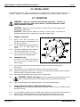
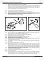
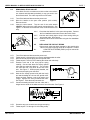
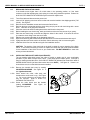
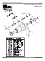
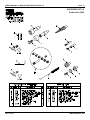
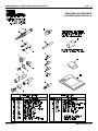
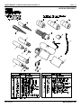
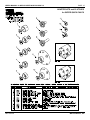
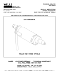
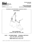
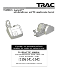
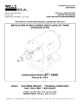
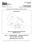
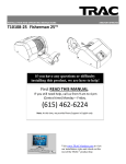
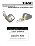
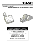
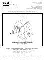
TECHNICAL BULLETIN
Q827-022510
DENTAL, INC.
5860 FLYNN CREEK ROAD
P.O. BOX 106
COMPTCHE, CALIFORNIA, U.S.A. 95427
www.wellsdental.com
READ ALL INSTRUCTIONS
BEFORE PROCEEDING
SAVE THIS FOR FUTURE REFERENCE
THIS PRODUCT IS FOR PROFESSIONAL LABORATORY USE ONLY
USER'S MANUAL
SUPER QUICK CHUCK LEFT
Product No. Q011
SALES
HAND
CUSTOMER SERVICE
TECHNICAL ASSISTANCE
CALL TOLL-FREE: 1 800 233-0521
PHONE: (707) 937-0521, FAX: (707) 937-2809
MONDAY-FRIDAY, 8:00 a.m.-4:30 p.m. P.S.T.
DENTAL EQUIPMENT FOR TECHNICIANS WHO VALUE TIME AND QUALITY
USER'S MANUAL for WELLS SUPER QUICK CHUCK LH
PAGE 2
1.0 SAFETY INSTRUCTIONS
WARNING:
WHEN USING ELECTRIC TOOLS, BASIC SAFETY
PRECAUTIONS SHOULD ALWAYS BE FOLLOWED TO REDUCE THE RISK OF
FIRE, ELECTRIC SHOCK, AND PERSONAL INJURY INCLUDING THE
FOLLOWING ITEMS:
Q827-022510
1.1
GROUND THE LATHE. The lathe must be grounded while in use to protect the user
from electric shock. Plug into a three hole grounded receptacle. If an adapter is used
to accommodate a two hole receptacle, the grounding lug must be connected to a
known ground. Never remove the third prong. If in doubt, have a licensed electrician
check the receptacle for PROPER GROUNDING and POLARITY.
1.2
HANDLE WITH DRY HANDS. Never handle the plug, power cord, lathe or Quick
Chuck with wet hands.
1.3
DISCONNECT THE POWER CORD. Before servicing, unplug the power cord to
prevent electric shock or unintentional starting.
1.4
ALWAYS USE SAFETY GLASSES. Wear industrial certified safety glasses for ALL
work and maintenance.
1.5
SECURE LOOSE ARTICLES. Fasten long hair. Do not wear loose clothing, necktie or
jewelry. They can get caught in rotating parts.
1.6
USE PARTICLE MASK when there is dust or particles in the air.
1.7
ALWAYS KEEP A TOOL IN THE COLLET. Never operate the unit without a tool.
1.8
DO NOT EXCEED THE MAXIMUM OPERATING SPEED OF THE TOOL. Use ONLY
tools, parting disks or polishing wheels that are rated above the speed of your lathe.
Insufficiently rated tools may break apart, bend or come loose causing serious personal
injury.
1.9
MAINTAIN THE WHEEL OR TOOL. Never operate with a damaged or bent tool. It
could break apart or come loose causing serious personal injury.
1.10
CHECK TOOL IS SECURE. Insert the tool shank into the collet to the MAXIMUM
depth that will allow free rotation of the tool. An extended tool is likely to break or bend
causing serious personal injury. Always check that the tool is securely held in the collet.
1.11
KEEP CHILDREN AWAY. All visitors should be kept a safe distance from the work
area. Do not run the unit unattended.
1.12
MAINTAIN THE UNIT. Inspect periodically for damaged or worn parts. Follow the
instructions for maintenance. Don't use if the power cord, motor, switch, or other parts
are in poor condition. Don't use if the unit has been dropped, damaged, or exposed to
water. Have a qualified service person inspect and replace parts when necessary.
1.13
FOR LABORATORY USE ONLY. The WELLS Super Quick Chuck is intended for use
by trained professional laboratory personnel.
WELLS DENTAL, INC.
USER'S MANUAL for WELLS SUPER QUICK CHUCK LH
PAGE 3
2.0 PRODUCT DESCRIPTION
The WELLS Super Quick Chuck is designed for heavy duty laboratory service, quiet operation, and low
maintenance. Tool changes are quick and safe. A quarter turn of the handle disengages the clutch, stops
the shaft and opens the collet all while the lathe is running. All 1/4" and 3/32" shank tools may be changed
instantly without adapters.
Q011 WELLS SUPER QUICK CHUCK LEFT HAND with accessories consists of:
SUPER QUICK CHUCK LEFT HAND and Q200 ACCESSORY KIT LH with:
Q124 ARBOR BAND 3/4 LH
Q132 SPIRAL CHUCK LEFT HAND
Q140 STONE CHUCK TOOTH & KNIFE LH (2)
Q152 MANDREL WITH 1-64 SCREW LH (2)
Q188 SET OF STOPS
Q193 COLLET WRENCH 4 JAW
Q194 TUBE BRUSH 3/8
151
HEX WRENCH 3/32
Q169 INSTALLATION SCREWS (4)
Q827 USER'S MANUAL
3.0 SPECIFICATIONS
COLLET SIZES 1/4" and 3/32"
TYPICAL OPERATING RPM .............................................................. 1725/3450 RPM
MAXIMUM LIMIT RPM................................................................................. 5000 RPM
UNIT DIMENSIONS (without lathe) ............................................... approx. 2.5 x 5 x 5"
WEIGHT (without lathe) ......................................................................................1.5 lbs
SHIPPING WEIGHT (without lathe) ...................................................................... 3 lbs
Figure 1. Quick Chuck features
Q827-022510
WELLS DENTAL, INC.
USER'S MANUAL for WELLS SUPER QUICK CHUCK LH
PAGE 4
4.0 INSTALLATION
The WELLS Super Quick Chuck fits universally on most dental lathes. Please refer to page 15 of this
manual for adapter kits. Separate technical bulletins for installation on the particular lathe are available.
5.0 OPERATION
WARNING: READ ALL INSTRUCTIONS BEFORE OPERATING. FAILURE TO
COMPLY WITH INSTRUCTIONS COULD RESULT IN SEVERE PERSONAL INJURY
AND/OR PROPERTY DAMAGE.
CAUTION: Always keep a tool in the collet. The Quick Chuck may be damaged if the
collet is closed without a tool.
CAUTION: Always ease the handle into position to close the collet. If the handle is
allowed to snap up or is forced upward it may damage the Quick Chuck.
5.1
GENERAL OPERATION
5.1.1
Work is done with the handle in the
operating position at approximately 2:30
o'clock. See Figure 2.
The clutch disengages when the handle is
moved down to approximately 3:30
o'clock.
The brake is applied when the handle is
moved to approximately 4:30 o'clock.
The collet opens when the handle is
moved to 6:00 o'clock (straight down).
5.1.2
5.1.3
5.1.4
5.2
5.2.1
CHANGING A TOOL
Any 3/32" or 1/4" shanked tool such as a
burr or chuck may be changed while the
lathe is running.
Figure 2.
5.2.4
From the operating position, move the handle to the open collet position (6:00 o'clock).
See Figure 2.
Remove the tool. (A 1/4" shanked tool will pop out when the collet is opened.)
Insert the selected tool into the collet. (To insert a 1/4" shanked tool, push the special collet back
inside the master collet with the shank of the tool.)
Move the handle to approximately 4:00 o'clock to close the collet.
5.2.5
DANGER: REMOVE YOUR HAND from the tool before moving the handle up past 3:30
5.2.2
5.2.3
o'clock. Holding a tool when the clutch engages could cause serious personal injury.
5.2.6
Ease the handle upward to the operating position. Do not let the handle snap up.
5.3
CHANGING BUFFING WHEELS, ARBOR BANDS AND STONES
By applying the brake, buffing wheels, arbor bands and stones may be loosened or tightened while
the lathe is running.
5.3.1
From the operating position move the handle down to about 4:30 o'clock where the resistance of
the brake is felt. This disengages the clutch, locks the shaft and keeps the collet closed.
Hold the handle in this position to loosen or tighten buffing wheels, arbor bands or stones.
5.3.2
Q827-022510
WELLS DENTAL, INC.
USER'S MANUAL for WELLS SUPER QUICK CHUCK LH
PAGE 5
6.0 MAINTENANCE
CAUTION: The bearings in the WELLS Super Quick Chuck are permanently lubricated with
special compounds. If anything enters the bearings, they will be damaged. KEEP OIL, SOLVENT
AND COMPRESSED AIR AWAY from the WELLS Super Quick Chuck.
CAUTION: There are no user serviceable parts inside the Quick Chuck except as described
below. DO NOT DISASSEMBLE the Quick Chuck.
6.1
RUNNING HOT
A Quick Chuck may run hot for several reasons:
6.1.1
A new or rebuilt Quick Chuck will run hot when first put into operation until the bearings are broken
in. This condition may last several days depending upon the amount of use.
The heat from the lathe motor is transferred to the Quick Chuck. The amount varies with the
particular lathe.
A worn or loose collet or a stop that is too long may cause tools to slip. The brake may drag
causing the collet to spin inside the collet body. The overheating will be noticed at the collet and
front of the collet body. If the tools slips, follow the procedures in section 6.3, FITTING A STOP TO
ADJUST THE COLLET DIAMETER.
6.1.2
6.1.3
6.2
6.2.1
6.2.2
6.2.3
6.2.4
6.2.5
6.2.6
6.2.7
6.2.8
6.2.9
6.2.10
CLEANING THE COLLETS (MONTHLY)
To prevent the collets from sticking and slipping, periodic cleaning and lubrication is essential.
Turn off the lathe and disconnect the power cord. Move the handle to the open collet position (6:00
o'clock). Remove the tool.
Insert the collet wrench into the master collet and turn counterclockwise to unscrew. If the collet
turns but will not unscrew, see section 6.4, REMOVING A STUCK COLLET.
Remove the master collet and the special collet. The pop-out spring, stop, and stop lock screw will
be attached to the special collet. It is not necessary to disassemble these parts.
Wash the collets in solvent. Solvent may be used on these parts ONLY when removed from the
collet body. Dry the parts thoroughly.
Clean the inside of the collet body so the master collet will seat against the stop properly. Clean the
threads using the tube brush provided in the accessory kit. Rotate the brush into the threads a few
times. Use a pipe cleaner or Q-tip to clean out all the debris in the bottom of the hole. Do not use
solvent here.
Put a THIN film of grease or Vaseline on the outside of both collets including the threads of the
master collet. DO NOT use oil.
Insert the collets and tighten with the collet wrench.
The special collet should protrude about 1/8". If not, remove the collets and carefully stretch or
compress the pop-out spring as needed.
Insert a tool into the collet and move the handle to the operating position.
Connect the power cord.
CAUTION: Do not run the Quick Chuck without the collets.
Q827-022510
WELLS DENTAL, INC.
USER'S MANUAL for WELLS SUPER QUICK CHUCK LH
PAGE 6
6.3
FITTING A STOP TO ADJUST THE COLLET DIAMETER
When the collets wear, tools may slip. The brake may drag causing the collet to spin inside the
collet body. A shorter stop must be installed to compensate for the wear. The shorter stop will
allow the master collet to thread further into the collet body so it grips more tightly. A set of 6 stops
of different lengths (Q188) is included with the accessory kit.
6.3.1
6.3.2
6.3.3
Turn off the lathe and disconnect the power cord.
Move the handle to the open collet position (6:00 o'clock) and remove the tool.
Insert the collet wrench into the master collet and turn counterclockwise to unscrew. If the collet
turns but will not unscrew, see section 6.4, REMOVING A STUCK COLLET.
Remove the master collet and the special collet. The pop-out spring, stop, and stop lock screw will
be attached to the special collet. See Figure 4.
6.3.4
Figure 3.
6.3.5
6.3.6
6.3.7
6.3.8
6.3.9
6.3.10
6.3.11
6.3.12
6.3.13
6.3.14
6.3.15
6.3.16
6.3.17
6.3.18
Q827-022510
Figure 4.
Remove the stop lock screw by LIGHTLY grasping the stop with a pair of pliers. Insert the 3/32
hex wrench into the end of the stop lock screw and unscrew it.
Unscrew the stop to remove it from the pop-out spring. Set the stop aside.
Follow steps 6.2.4 and 6.2.5 for cleaning the collets.
Count the number of marks on the surface of the stop you set aside.
Choose a new stop with one mark less (the next shorter size).
Screw the new stop onto the pop-out spring.
Screw the stop lock screw into the stop. LIGHTLY grasp the stop with the pliers. Tighten the stop
lock screw with the 3/32 hex wrench.
Put a THIN film of grease or Vaseline on the outside of both collets including the threads of the
master collet.
Insert the collets and tighten with the collet wrench.
Make sure that the handle is in the open collet position (6:00 o'clock). Insert the test rod that
comes with the set of stops (or a 1/4" tool shank) into the master collet. The test rod should just
slip into the collet. If it is loose, start at step 6.3.2 and install a shorter stop. If the test rod will not fit
into the master collet or is too tight, start at step 6.3.2 and install a longer stop. Install the shortest
stop that will allow the test rod to just slip into the master collet.
The special collet should protrude about 1/8". If not, remove the collets and carefully stretch or
compress the pop-out spring as needed.
Insert a tool into the collet and move the handle to the operating position.
Connect the power cord.
If tools still slip or the collet overheats, both collets should be replaced (Q146 MASTER COLLET
and Q148 SPECIAL COLLET WITH SPRING). Follow the procedure above, section 6.3, when
installing new collets. The set of stops (Q188) included with the accessory kit will be needed.
WELLS DENTAL, INC.
USER'S MANUAL for WELLS SUPER QUICK CHUCK LH
PAGE 7
6.4
REMOVING A STUCK COLLET
If the Quick Chuck is run without a tool in the collet or the collet is
not cleaned and lubricated periodically it may get stuck in the
Quick Chuck shaft. The collet may turn but not unscrew.
6.4.1
6.4.2
Turn off the lathe and disconnect the power cord.
Move the handle to the open collet position (6:00 o'clock).
Remove the tool.
Insert the collet wrench. Tap the end of the collet wrench
LIGHTLY while turning the collet wrench counterclockwise. See
Figure 5. If this does not release the collet, continue with the next Figure 5.
step.
6.4.4
Check that the handle is in the open collet position. Remove
the four installation screws and remove the Quick Chuck.
6.4.5
Hold the steel clutch plate to keep it from turning while you
remove the collet. See Figure 6.
6.4.6
Install the Quick Chuck on the lathe using the four installation
screws.
6.4.3
6.5
Figure 6.
6.5.1
6.5.2
6.5.3
6.5.4
6.5.5
6.5.6
6.5.7
No.
REPLACING THE POP-OUT SPRING
If the pop-out spring has been damaged or the special collet
falls out, the pop-out spring needs to be replaced. Product
Q186 POP-OUT SPRING (PKG-2) may be ordered for
replacement.
Turn off the lathe and disconnect the power cord.
Follow steps 6.3.2 through 6.3.6 to remove and disassemble the collet.
Remove the old pop-out spring from the special collet.
Follow steps 6.2.4 and 6.2.5 for cleaning the collets and collet body.
Examine each end of the new pop-out spring
carefully. One end has about five closely spaced
coils while the other has about six. The end with
five coils also has a tiny hook at the end of the
wire. See Figure 7. When properly installed, this
hook locks the spring onto the collet.
Hold the five closely spaced coils (with the hook)
and start threading the coil onto the special collet.
When the hook reaches a slot it will tend to get
caught. Squeeze the coils just behind the hook.
Figure 7.
See Figure 7. Ease the hook past each slot.
Continue threading the hook onto the collet until it
lodges into the center of the widened area of one of the slots. See Figure 8.
Figure 8.
6.5.8
6.5.9
Q827-022510
Screw the stop you set aside onto the pop-out spring.
Follow steps 6.3.11 through 6.3.16 for fitting a stop.
WELLS DENTAL, INC.
USER'S MANUAL for WELLS SUPER QUICK CHUCK LH
PAGE 8
6.6
ADJUSTING THE CLUTCH SPRING
If the handle does not have enough spring tension when the
handle is in the operating position, the clutch may slip.
6.6.1
6.6.2
Move the handle to the operating position (2:30 o'clock).
CAUTION: The number cap is under spring tension and will
twist when loosened. Carefully loosen the set screw in the side
of the number cap.
Turn the number cap clockwise against the spring tension until
the set screw is facing straight up (12:00 o'clock). Be sure the
handle is still in the operating position (2:30 o'clock). Tighten
the set screw. See Figure 9. If there is no spring tension, the
spring is damaged; go to section 6.7, REPLACING THE Figure 9.
CLUTCH SPRING.
If the clutch still slips, loosen the set screw and turn the number cap a little more in the clockwise
direction to increase the spring tension. Tighten the set screw.
6.6.3
6.6.4
6.7
REPLACING THE CLUTCH SPRING
If there is no spring tension when attempting to adjust the clutch spring, it is damaged and must be
replaced. Order part number Q183 CLUTCH SPRING LH.
6.7.1
6.7.2
6.7.3
Move the handle to the operating position (2:30 o'clock).
Loosen the handle set screw and remove the handle.
Loosen the set screw in the side of the number cap, lift off the number cap, remove and discard the
damaged clutch spring.
Insert the short end of the new spring into the small hole inside the number cap.
Holding the spring in place with the tip of your finger (or pair of needle nose pliers), turn the number
cap over and carefully insert the long end of the spring into the small hole in the Quick Chuck
housing. Be sure the short end of the spring is still in the hole in the number cap. The number cap
should drop into place so the handle fits through its hole. If the number cap has to be pushed
down, the spring is not installed correctly.
Install the handle and tighten the handle set screw.
Turn the number cap clockwise against the spring tension until the number cap set screw is facing
straight up (12:00 o'clock). Be sure the handle is still in the operating position (2:30 o'clock).
Tighten the number cap set screw. See Figure 9.
6.7.4
6.7.5
6.7.6
6.7.7
6.8
FIXING A SQUEAKY CLUTCH
Over a period of time, the clutch may glaze and develop a squeak especially when the lathe is
coasting to a stop.
6.8.1
6.8.2
6.8.3
6.8.4
6.8.5
6.8.6
Turn off the lathe and disconnect the power cord.
Move the handle to the shipping position (7:30 o'clock).
Remove the four installation screws and remove the Quick Chuck.
Lightly sand both the fiber and the steel clutch surfaces to remove the glaze.
Install the Quick Chuck on the lathe using the four installation screws and connect the power cord.
If the squeak persists and there is excessive dust around the clutch area, the adapter is
misaligned. Refer to the technical bulletin for the installation of the Quick Chuck on your model
lathe. Some lathes are improperly machined for correct adapter alignment. These lathes should
be shipped to Wells Dental, Inc. for Quick Chuck installation.
Q827-022510
WELLS DENTAL, INC.
USER'S MANUAL for WELLS SUPER QUICK CHUCK LH
PAGE 9
6.9
REPLACING THE CLUTCH LINING
If the handle moves higher than 1:30 o'clock when in the operating position, or if the clutch
continues to slip after adjusting the clutch spring, the clutch lining should be replaced. Product No.
Q150 CLUTCH LINING WITH SCREWS may be ordered for replacement.
6.9.1
6.9.2
Turn off the lathe and disconnect the power cord.
Insert a 3/32" shipping rod or burr into the collet and move the handle to the shipping position (7:30
o'clock). See Figure 2.
Remove the four installation screws and remove the Quick Chuck.
Remove the three screws that hold the clutch lining and pry out the old clutch lining with a screw
driver. Take care not to gouge the clutch hub.
Clean the clutch hub and surrounding area with a small brush or shop towel.
Before handling the new clutch lining, wash your hands to make sure they are not oily or greasy.
Place the new clutch lining on the hub and align the holes for the screws. If the holes do not line
up, rotate the clutch lining to the next set of holes.
Start the new screws and tighten in an alternating sequence.
Wipe the clutch lining with a cloth soaked with clean solvent if it becomes darkened with any oil.
Lightly sand the steel clutch surface of the Quick Chuck with emory cloth to remove the glaze.
Install the Quick Chuck on the lathe using the four installation screws.
6.9.3
6.9.4
6.9.5
6.9.6
6.9.7
6.9.8
6.9.9
6.9.10
6.9.11
CAUTION: The position of the clutch hub on the shaft is critical for proper operation of the Quick
Chuck. If it becomes necessary to remove or replace the clutch hub, refer to the technical bulletin
for the installation of the Quick Chuck on your model lathe. DO NOT REMOVE the clutch hub
unless you have this bulletin.
6.10
INSTALLING THE COLLET SHIELD (ACCESSORY)
The non-rotating collet shield covers the collet to provide a steady rest for more comfortable
operation of your WELLS Super Quick Chuck. It also helps protect rubber gloves. Removal is
easy for cleaning around the collet. Q103 COLLET SHIELD LH (left hand) fits model Q011 WELLS
SUPER QUICK CHUCK (left hand with knurled dust cover ONLY) . See figure 10. If there is no
knurled dust cover, the collet shield cannot be installed.
6.10.1
Remove the knurled dust cover by rotating
COUNTERCLOCKWISE. See Figure 10. It
has right-hand threads.
Clean around the collet, collet body and
threads with a small brush or rag. See Figure
11. Do not use solvent on the collets unless
they are removed. Refer to section 6.2,
CLEANING THE COLLETS.
Screw the collet shield onto the threads
rotating CLOCKWISE.
See Figure 12.
Tighten firmly by hand.
6.10.2
6.10.3
Figure 10.
Q827-022510
WELLS DENTAL, INC.
USER'S MANUAL for WELLS SUPER QUICK CHUCK LH
PAGE 10
6.11
CLEANING THE COLLET SHIELD
Accumulated material should be removed
periodically.
6.11.1
Unscrew the collet shield by turning
COUNTERCLOCKWISE. Be sure to rotate in
the correct direction.
It has right-hand
threads.
Clean around the collet, collet body and
threads with a small brush or rag. See Figure
11. Do not use solvent on the collets unless
they are removed. Refer to section 6.2,
CLEANING THE COLLETS. Use solvent to
clean the collet shield when it is removed.
Figure 11.
Screw the collet shield onto the threads by
rotating CLOCKWISE. See Figure 12. Tighten firmly by hand.
6.11.2
6.11.3
Figure 12.
For further maintenance or repairs, send Quick Chuck to WELLS DENTAL, INC. for factory service.
6.12
REMOVING THE QUICK CHUCK FROM THE LATHE
6.12.1
Insert a 3/32" shipping rod or burr into the collet and move the handle to the shipping position (4:30
o'clock). See Figure 2.
Remove the four installation screws and remove the Quick Chuck.
6.12.2
Q827-022510
WELLS DENTAL, INC.
USER'S MANUAL for WELLS SUPER QUICK CHUCK LH
PAGE 11
PARTS LIST for SUPER QUICK CHUCK LH
Product No. Q011
Q827-022510
WELLS DENTAL, INC.
USER'S MANUAL for WELLS SUPER QUICK CHUCK LH
PAGE 12
ACCESSORY KIT LH
Product No. Q200
Q827-022510
WELLS DENTAL, INC.
USER'S MANUAL for WELLS SUPER QUICK CHUCK LH
PAGE 13
ADDITIONAL ACCESSORIES
for SUPER QUICK CHUCK LH
Q827-022510
WELLS DENTAL, INC.
USER'S MANUAL for WELLS SUPER QUICK CHUCK LH
PAGE 14
LATHE ACCESSORIES
Q827-022510
WELLS DENTAL, INC.
USER'S MANUAL for WELLS SUPER QUICK CHUCK LH
PAGE 15
ADAPTER KITS and CLUTCHES
for SUPER QUICK CHUCK
Q827-022510
WELLS DENTAL, INC.
USER'S MANUAL for WELLS SUPER QUICK CHUCK LH
PAGE 16
NOTES
Q827-022510
WELLS DENTAL, INC.