1
Model 842-E-USB
Dual Channel
Virtual Power/Energy Meter
User’s Manual
2
Preface
EU Declaration of Conformity
We declare that the accompanying product, identified with the mark,
complies with requirements of the Electromagnetic Compatibility Directive,
200489/108336/EEC and the Low Voltage Directive 73/23/EEC.
Model Number: 842-E-USB
Year
mark affixed: 2008
Type of Equipment: Electrical equipment for measurement, control and
laboratory use
Manufacturer: Newport Corporation
1791 Deere Avenue
Irvine, CA 92606
Standards Applied:
Compliance was demonstrated to the following standards to the extent
applicable:
Standard
Description
EN 61326
:1997
Limits and methods of measurement of radio interference
characteristics of information technology equipment.
Testing and measurements of conducted emission
EN 61326 :
1997
Limits and methods of measurement of radio interference
characteristics of information technology equipment.
Testing and measurements of radiated emission
Electromagnetic compatibility (EMC) – Part 4: Testing
and measurements techniques- Section 4.2: Electrostatic
discharge.
Class A
EN 61000-43:1996
Electromagnetic compatibility (EMC) – Part 4: Testing
and measurements techniques- Section 3: Radiated,
Radio Frequency immunity.
Class A
ENV 50204:
1995
EN 61000-44:1995
Radiated Electromagnetic field from digital radio
telephones- immunity test 900MHz pulsed
Electromagnetic compatibility (EMC) – Part 4: Testing
and measurements techniques- Section 4: Electrical fast
transient/burst immunity.
Class A
EN 61000-46:1996
Electromagnetic compatibility (EMC) – Part 4: Testing
and measurements techniques- Section 6: Immunity to
conducted Radio Frequency.
Class A
EN 61000-42:1995
Dominique Devidal
Quality Director
Zone Industrielle
45340 Beaune-la-Rolande, France
Performance
Criteria
Class A
Class B
Class B
Manny Del Valle
Senior Manager, Product
Development
1791 Deere Avenue
Irvine, CA USA
3
Preface
Manual Updates
Dear Customer,
In an effort to keep the product you purchased optimized for
your applications, Newport will on occasion update existing,
and add new features to this instrument.
To utilize this new functionality will require an update to the
instrument's firmware, which can be easily accomplished by
the user, as described in this operator manual. As required,
Newport will also generate a new version of this user
manual, reflecting updates to the instrument.
Please check the Newport website (www.Newport.com)
for newer versions of the firmware and the operator manual,
which can be downloaded as a PDF file. Call your local
Newport application specialist if you need support with
locating or downloading these files.
Enjoy your new instrument!
4
Preface
Warranty
Newport Corporation warrants that this product will be free from defects in
material and workmanship and will comply with Newport’s published
specifications at the time of sale for a period of one year from date of
shipment. If found to be defective during the warranty period, the product
will either be repaired or replaced at Newport's option.
To exercise this warranty, write or call your local Newport office or
representative, or contact Newport headquarters in Irvine, California. You
will be given prompt assistance and return instructions. Send the product,
freight prepaid, to the indicated service facility. Repairs will be made and the
instrument returned freight prepaid. Repaired products are warranted for the
remainder of the original warranty period or 90 days, whichever first occurs.
Limitation of Warranty
The above warranties do not apply to products which have been repaired or
modified without Newport’s written approval, or products subjected to
unusual physical, thermal or electrical stress, improper installation, misuse,
abuse, accident or negligence in use, storage, transportation or handling. This
warranty also does not apply to fuses, batteries, or damage from battery
leakage.
THIS WARRANTY IS IN LIEU OF ALL OTHER WARRANTIES,
EXPRESSED OR IMPLIED, INCLUDING ANY IMPLIED WARRANTY
OF MERCHANTABILITY OR FITNESS FOR A PARTICULAR USE.
NEWPORT CORPORATION SHALL NOT BE LIABLE FOR ANY
INDIRECT, SPECIAL, OR CONSEQUENTIAL DAMAGES RESULTING
FROM THE PURCHASE OR USE OF ITS PRODUCTS.
First printing 2011
© 2011 by Newport Corporation, Irvine, CA. All rights reserved. No part of
this manual may be reproduced or copied without the prior written approval
of Newport Corporation.
This manual has been provided for information only and product
specifications are subject to change without notice. Any change will be
reflected in future printings.
Newport Corporation
1791 Deere Avenue
Irvine, CA, 92606
USA
Part No. 90043186 rev A
5
Preface
Confidentiality & Proprietary Rights
Reservation of Title:
The Newport programs and all materials furnished or produced in connection
with them ("Related Materials") contain trade secrets of Newport and are for
use only in the manner expressly permitted. Newport claims and reserves all
rights and benefits afforded under law in the Programs provided by Newport
Corporation.
Newport shall retain full ownership of Intellectual Property Rights in and to
all development, process, align or assembly technologies developed and other
derivative work that may be developed by Newport. Customer shall not
challenge, or cause any third party to challenge the rights of Newport.
Preservation of Secrecy and Confidentiality and Restrictions to Access:
Customer shall protect the Newport Programs and Related Materials as trade
secrets of Newport, and shall devote its best efforts to ensure that all its
personnel protect the Newport Programs as trade secrets of Newport
Corporation. Customer shall not at any time disclose Newport's trade secrets
to any other person, firm, organization, or employee that does not need
(consistent with Customer's right of use hereunder) to obtain access to the
Newport Programs and Related Materials. These restrictions shall not apply
to information (1) generally known to the public or obtainable from public
sources; (2) readily apparent from the keyboard operations, visual display, or
output reports of the Programs; 3) previously in the possession of Customer
or subsequently developed or acquired without reliance on the Newport
Programs; or (4) approved by Newport for release without restriction.
Service Information
This section contains information regarding factory service for the source.
The user should not attempt any maintenance or service of the system or
optional equipment beyond the procedures outlined in this manual. Any
problem that cannot be resolved should be referred to Newport Corporation.
Copyright and Trademark Information
WINDOWSTM is a registered Trademark of Microsoft Corporation
Visual Basic is a registered Trademark of Microsoft Corporation.
Visual C++ is a registered Trademark of Microsoft Corporation.
6
Preface
Technical Support Contacts
North America & Asia
Europe
Newport Corporation Service Dept.
1791 Deere Ave. Irvine, CA 92606
Telephone: (949) 253-1694
Telephone: (800) 222-6440 x31694
Newport/MICRO-CONTROLE S.A.
Zone Industrielle
45340 Beaune la Rolande, FRANCE
Telephone: (33) 02 38 40 51 56
Asia
Newport Opto-Electronics
Technologies (Wuxi) Co.
No. 36, 38 Xikun Road, WSIP, Wuxi,
Jiangsu, 214028 China
Telephone: +86-510-8018-3000
Fax: +86-510-8018-3289
Newport Corporation Calling Procedure
If there are any defects in material or workmanship or a failure to meet
specifications, promptly notify Newport's Returns Department by calling 1-800-2226440 or by visiting our website at www.newport.com/returns within the warranty
period to obtain a Return Material Authorization Number (RMA#). Return the
product to Newport Corporation, freight prepaid, clearly marked with the RMA# and
we will either repair or replace it at our discretion. Newport is not responsible for
damage occurring in transit and is not obligated to accept products returned without
an RMA#.
E-mail: [email protected]
When calling Newport Corporation, please provide the customer care representative
with the following information:
Your Contact Information
Serial number or original order number
Description of problem (i.e., hardware or software)
To help our Technical Support Representatives diagnose your problem, please note
the following conditions:
Is the system used for manufacturing or research and development?
What was the state of the system right before the problem?
Have you seen this problem before? If so, how often?
Can the system continue to operate with this problem? Or is the system nonoperational?
Can you identify anything that was different before this problem occurred?
7
Preface
IMPORTANT NOTE
Before plugging the instrument into a PC via a USB communication port, please
make sure that the USB Drivers are installed. Run Setup.exe from the Software CD
that came with your product. The installation program will configure the PC with the
USB drivers.
8
Preface
Table of Contents
EU Declaration of Conformity............................................................... 2
Warranty................................................................................................. 4
Technical Support Contacts ................................................................... 6
Table of Contents ................................................................................... 8
List of Figures ...................................................................................... 10
1
Safety Precautions
1.1
1.2
1.3
2
2.3
2.4
2.5
3
21
Connector Descriptions .............................................................. 21
System Operation
4.1
4.2
16
Introduction ................................................................................ 16
Unpacking and Handling............................................................ 17
2.2.1 Parts List..........................................................................17
Inspection for Damage ............................................................... 18
Calibration .................................................................................. 18
Specifications ............................................................................. 18
System Overview
3.1
4
Definitions and Symbols ............................................................ 12
1.1.1 General Warning or Caution ...........................................12
1.1.2 Electric Shock..................................................................12
1.1.3 European Union CE Mark ...............................................12
1.1.4 Waste Electrical and Electronic Equipment (WEEE) .....13
1.1.5 Control of Hazardous Substances....................................13
Warnings and Cautions............................................................... 13
1.2.1 General Warnings............................................................14
1.2.2 General Cautions .............................................................14
Additional Safety Information.................................................... 15
General Information
2.1
2.2
12
23
Quick Startup Guide ................................................................... 23
User Interface ............................................................................. 25
4.2.1 Real Time Display...........................................................26
4.2.2 Status Window.................................................................27
4.2.3 Selecting the Channel to Display ....................................27
4.2.4 Adjusting the Window Display .......................................27
4.2.5 Graphic Display...............................................................28
4.2.6 Graphic Mode Option After Opening a File Using Load
File Menu.........................................................................30
4.2.7 Restarting the Lineplot, Statistics, and Histogram ..........30
4.2.8 Data Acquisition..............................................................31
4.2.9 Pausing the Statistics and Lineplot..................................32
4.2.10 Zeroing ............................................................................32
4.2.11 Ratio Measurement..........................................................32
4.2.12 Detecting Missing Laser Pulses.......................................33
9
Preface
5
Software Installation
5.1
5.2
5.3
6
7
Recommended Specifications of PC .......................................... 35
Installation And Communication ............................................... 37
5.2.1 Installation of Application Software ...............................37
5.2.2 Installation of USB drivers for WindowsTM ....................37
Setting Up Communication to 842-E-USB ................................ 37
5.3.1 Verifying COM Port........................................................37
5.3.2 Installation of the PC Software........................................37
5.3.3 Running the Software ......................................................38
5.3.3.1 Start the software application................................ 38
5.3.3.2 Ensure that the correct COM port is selected ....... 38
5.3.3.3 Exit the software application ................................ 38
5.3.4 Connecting 842-E-USB...................................................38
5.3.5 Echo On/Off ....................................................................39
5.3.6 Testing Connection..........................................................39
5.3.7 HyperTerminal Setting Shortcut......................................39
Communication Command Reference
6.1
9
48
Introduction ................................................................................ 48
Procedure.................................................................................... 48
Appendix B – Disassembly Instructions
9.1
9.2
9.3
45
Enclosure Cleaning..................................................................... 45
USB connector for 842-E-USB .................................................. 45
Free Software Upgrade............................................................... 45
Obtaining Service ....................................................................... 46
Service Form .............................................................................. 47
8
Appendix A – Attenuator / Diffuser Calibration
Procedure
8.1
8.2
40
Command Description................................................................ 40
6.1.1 Command Glossary .........................................................40
Maintenance and Service
7.1
7.2
7.3
7.4
7.5
35
50
Recycling and Separation Instruction......................................... 50
Separation ................................................................................... 50
Disassembly................................................................................ 50
10 Appendix C – Avoiding COM Port Increment
51
10.1 Procedure.................................................................................... 51
10.1.1 Installing FT-PROG.exe Program ...................................51
10.1.2 Running FT-PROG.exe Program ....................................51
10
Preface
List of Figures
Figure 1
Figure 2
Figure 3
Figure 4
Figure 5
Figure 6
Figure 7
Figure 8
Figure 9
Figure 10
Figure 11
Figure 12
Figure 13
Figure 14
Figure 15
Figure 16
Figure 17
Figure 18
Figure 19
General Warning or Caution Symbol............................................. 12
Electrical Shock Symbol ................................................................ 12
CE Mark ......................................................................................... 12
WEEE Directive Symbol ............................................................... 13
RoHS Compliant Symbol............................................................... 13
842-E-USB Virtual Power/Energy Meter ...................................... 16
PC 842-E-USB User Interface ....................................................... 17
Rear View of 842-E-USB .............................................................. 21
Trigger zone of 842-E-USB ........................................................... 21
Detector connectors for 842-E-USB .............................................. 22
Communication Initialization ........................................................ 25
Real Time Display ......................................................................... 26
Status Window ............................................................................... 27
Display Menu ................................................................................. 28
Graphical Display .......................................................................... 29
Graphical Display Settings............................................................. 29
Clear and Clear All options............................................................ 31
Data Acquisition Mode .................................................................. 32
Ratio Measurement ........................................................................ 33
11
Preface
This page is intentionally left blank
1
1.1
Safety Precautions
Definitions and Symbols
The following terms and symbols are used in this documentation and also
appear on the Model 842-E-USB Optical Power/Energy Meter where safetyrelated issues occur.
1.1.1
General Warning or Caution
Figure 1
General Warning or Caution Symbol
The Exclamation Symbol in the figure above appears in Warning and Caution
tables throughout this document. This symbol designates an area where
personal injury or damage to the equipment is possible.
1.1.2
Electric Shock
Figure 2
Electrical Shock Symbol
The Electrical Shock Symbol in the figure above may appear throughout this
manual. This symbol indicates a hazard arising from dangerous voltage.
Any mishandling could result in irreparable damage to the equipment, and
personal injury or death.
1.1.3
European Union CE Mark
Figure 3
CE Mark
The presence off the CE Mark on Newport Corporation equipment means that
it has been designed, tested and certified as complying with all applicable
European Union (CE) regulations and recommendations.
General Information
1.1.4
13
Waste Electrical and Electronic Equipment (WEEE)
Figure 4
WEEE Directive Symbol
This symbol on the product or on its packaging indicates that this product
must not be disposed of with regular waste. Instead, it is the user
responsibility to dispose of waste equipment according to the local laws. The
separate collection and recycling of the waste equipment at the time of
disposal will help to conserve natural resources and ensure that it is recycled
in a manner that protects human health and the environment. For information
about where the user can drop off the waste equipment for recycling, please
contact your local Newport Corporation representative. See Section 9 for
instructions on how to disassemble the equipment for recycling purposes.
1.1.5
Control of Hazardous Substances
Figure 5
RoHS Compliant Symbol
This label indicates the products comply with the EU Directive 2002/95/EC
that restricts the content of six hazardous chemicals.
1.2
Warnings and Cautions
The following are definitions of the Warnings, Cautions and Notes that are
used throughout this manual to call your attention to important information
regarding your safety, the safety and preservation of your equipment or an
important tip.
WARNING
Situation has the potential to cause bodily harm or death.
14
General Information
CAUTION
Situation has the potential to cause damage to property or
equipment.
NOTE
Additional information the user or operator should consider.
1.2.1
General Warnings
Observe these general warnings when operating or servicing this
equipment:
Heed all warnings on the unit and in the operating instructions.
Do not use this equipment in or near water.
Disconnect power before cleaning the equipment. Do not use liquid or
aerosol cleaners; use only a damp lint-free cloth.
Lockout all electrical power sources before servicing the equipment.
To avoid explosion, do not operate this equipment in an explosive
atmosphere.
Qualified service personnel should perform safety checks after any
service.
1.2.2
General Cautions
Observe these cautions when operating or servicing this equipment:
If this equipment is used in a manner not specified in this manual, the
protection provided by this equipment may be impaired.
Follow precautions for static sensitive devices when handling this
equipment.
This product should only be powered as described in the manual.
There are no user-serviceable parts inside the 842-E-USB Optical
Power/Energy Meter.
To prevent damage to the equipment, read the instructions in the
equipment manual for proper input voltage.
Adhere to good laser safety practices when using this equipment.
General Information
1.3
15
Additional Safety Information
Do not use the 842-E-USB if the instrument or the detector looks damaged,
or if you suspect that the 842-E-USB is not operating properly.
Appropriate installation must be done for water-cooled and fan-cooled
detectors. Refer to the specific instructions for more information. The user
must wait for a while before handling these detectors after power is applied.
Surfaces of the detectors get very hot and there is a risk of injury if they are
not allowed to cool down.
Note: This equipment has been tested and found to comply with the limits for
a Class B digital device, pursuant to part 15 of the FCC Rules. These limits
are designed to provide reasonable protection against harmful interference in
a residential installation. This equipment generates, uses, and can radiate
radio frequency energy and, if not installed and used in accordance with the
instructions, may cause harmful interference to radio communications.
However, there is no guarantee that interference will not occur in a particular
installation. If this equipment does cause harmful interference to radio or
television reception, which can be determined by turning the equipment off
and on, it is suggested to try to correct the interference by taking one or more
of the following steps:
Reorient or relocate the receiving antenna.
Increase the distance between the equipment and receiver.
Connect the equipment to an outlet that is on a different circuit than
the receiver.
Consult the dealer or an experienced radio/TV technician for help.
16
General Information
2
2.1
General Information
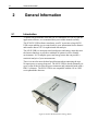
Introduction
To obtain full performance from the 842-E-USB and the PC 842-E-USB, the
application software, we recommend that you read this manual carefully.
The PC 842-E-USB software transforms your PC screen into a large 842-EUSB screen enabling you to control and see your information from a distance
and transfer data to a PC for sophisticated data analysis.
The 842-E-USB is a microprocessor-based power and energy meter that uses
the latest technology to provide a multitude of options in a user-friendly
environment. It is a complete power and energy meter that can provide a
statistical analysis of your measurements.
There is no need to enter the head specifications when connecting the new
Newport power or energy detectors. The 842-E-USB is already internally set
up to accept all the Newport Hi power wattmeter and joulemeter heads with a
DB-15 connector. The 842-E-USB is not compatible with the 818 or 918D
series photodiode detectors.
Figure 6 842-E-USB Virtual Power/Energy Meter
General Information
17
Figure 7 PC 842-E-USB User Interface
2.2
Unpacking and Handling
Each Newport 842-E-USB is thoroughly tested and calibrated prior to
shipment.
It is recommended that the Model 842-E-USB Virtual Power/Energy Meter
be unpacked in a lab environment or work site. Unpack the system carefully;
small parts and cables are included with the instrument.
You can download the latest software version for the PC 842-E-USB (and
install it on your PC) and for the 842-E-USB (and install it on the 842-EUSB) with the serial interface anytime from our website www.newport.com.
You can download the PC 842-E-USB program from our website. Go to the
Downloads section of our website: www.newport.com. Click on the file
name and download it to your PC. The specific actions necessary vary
between browser and browser settings. After it is transferred, open the file on
your PC and follow the instructions to uncompress and install it.
2.2.1
Parts List
The following is a list of parts included with the 842-E-USB Handheld Power
Meter. Please make sure everything is present before discarding packing
materials.
842-E-USB Dual Channel, Virtual Optical Power/Energy Meter
USB cable
A CD containing software and user manual
18
General Information
2.3
Inspection for Damage
The Model 842-E-USB Optical Power/Energy Meter is carefully packaged at
the factory to minimize the possibility of damage during shipping. Inspect
the box for external signs of damage or mishandling. Inspect the contents for
damage. If there is visible damage to the instrument upon receipt, inform the
shipping company and Newport Corporation immediately. Any damage claim
should be made promptly to the transportation company. It is strongly
recommended that you save the packaging material in case you need to ship
your equipment in the future.
WARNING
Do not attempt to operate this equipment if there is evidence of
shipping damage or you suspect the unit is damaged. Damaged
equipment may present additional hazards to you. Contact
Newport technical support for advice before attempting to plug
in and operate damaged equipment.
2.4
Calibration
Calibration of the power meter is done at the factory by defining a slope and
offset, for all ranges as determined for each detector type.
Newport recommends annual factory re-calibration to ensure the continued
accuracy of power meter measurements.
Please refer to the “Maintenance and Troubleshooting” section for contact
information for re-calibration of your power meter.
2.5
Specifications
The following specifications are based on a one-year calibration cycle, an
operating temperature of 18 to 28ºC (64 to 82ºF) and a relative humidity not
to exceed 80%.
Power meter specifications
Power Range
1 uW to 10 kW
Power Scales
(thermal head)
15 scales: 300uW, 1 mW, 3mW, 30mW, 100mW,
300mW, 1W, 3W, 10W, 30W, 100W, 300W, 1kW,
3kW, 10kW
Resolution (digital)
Normal mode: Current scale/2048
ASCII mode: Current scale/32768
General Information
19
Wattmeter mode Accuracy
±0.75 % 2.5 µV from 10% to full scale 1
Response Time (accelerated) 2
1 sec
Sampling Frequency
100 Hz
Statistics
Current value, Max, Min, Average, Std Dev., RMS
stability, PTP stability, Time
Energy meter specifications
Energy Range
0.08µJ to 20 kJ
Energy Scales
20 scales: 10uJ, 30uJ, 100µJ, 300µJ, 1mJ, 3mJ, 10mJ,
30mJ, 100mJ, 300mJ, 1J, 3J, 10J, 30J, 100J, 300J, 1kJ,
3kJ, 10kJ, 30kJ
Resolution (digital)
Normal mode: Current scale/4096
Ascii mode: Current scale/32768
Accuracy
3
1.0 %50 µV < 500 Hz
2.0 %50 µV 500 Hz to 1.2 kHz
3%50 µV 1.2 kHz to 6 kHz
6%50 µV 6kHz to 10 kHz
Average Power accuracy
Frequency Accuracy error + Joulemeter accuracy.
Frequency Accuracy
0.1 to 1000 Hz : 1%±0.1 Hz4
1000 to 2000 Hz : 2%±0.1 Hz4
5000 to 10000 Hz : 3%±1 Hz4
Default Trigger Level
2%
Software Trigger Level
0.1% to 99.9%, 0.1% resolution
Real Time Data Transfer
10 kHz/Channel in Normal mode no missing point
with USB 2.0 or Ethernet and recommended PC.
Statistics
Current value, Max, Min, Average, Std Dev., RMS
stability, PTP stability, Pulse #, Repetition Rate, Avg
Power
Data Storage
Limited to PC hard drive free space
1
The 2.5µV bias can introduce an error into low power measurements with low sensitivity detectors. It is essential
to use the Zero Offset to rezero the 842-E-USB before making a measurement in these conditions. It is always good
practice to use the Zero Offset. See section 2.2.
2
Varies with detector head.
3
Including linearity.
4
With the recommended PC, no graphic display, usb latency set to 1ms and no other applications running.
20
General Information
General Specifications
Digital Display
Computer screen
Display Rate
3 Hz in Real time mode.
15 Hz in Graphic mode.
Data Displays
Real time, Ratio, Line plot, Histogram, Statistics and
3D Histogram.
User input correction factors
1 multiplier and 1 offset (7 digits floating point)
Positive External trigger
3 to 24 V @ 13 mA, optically isolated.
External trigger pulse width
2 us minimum, no maximum time.
Internet Upgrades
Yes
PC Serial Commands
Yes
Dimensions
147 (L) x 106 (W) x 34 (H) mm
(connectors included)
Weight
0.424 kg
Power Over USB
Yes
3
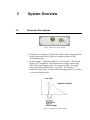
3.1
System Overview
Connector Descriptions
Figure 8 Rear View of 842-E-USB
1. USB Interface Connector – This interface allows remote control and data
transfers between the 842-E-USB and a computer that has a USB
communication port.
2. External Trigger – The Input connector is a Female BNC. The External
trigger is TTL compatible. The monitor detects a trigger on the rising
side of the external trigger signal. To measure accurately, the trigger
must be just before the laser pulse, or just after. For Example, a
Joulemeter with a 20uS rise time, the External trigger must be 4 us before
or 19us after the laser pulse.
Figure 9 Trigger zone of 842-E-USB
22
System Overview
Figure 10 Detector connectors for 842-E-USB
3. DB15 Detector Connectors – The 842-E-USB uses a DB-15 female
connector to mate with the detector heads (probes).
4
4.1
System Operation
Quick Startup Guide
This section applies to all 842-E-USB versions. It quickly shows you how to
make a laser power and energy measurement with the 842-E-USB and a
Newport power (818P series) or energy detector (818E series).
The monitor automatically recognizes all the compatible Newport detectors.
All custom technical data required for optimum operation of the detector will
be automatically downloaded from the EEPROM in the DB-15 connector.
This data includes sensitivity, model, serial number, version, wavelength
correction factors, and time response.
The first 11 steps are for 842-E-USB initialization, and steps 12 to 14 refer to
the PC interface with 842-E-USB.
1. Install the power or energy detector head.
2. Turn the 842-E-USB off (unplug it) and connect a version 5 (or higher)
power or energy detector head to the 842-E-USB using the Detector
INPUT DB15. Turn the 842-E-USB off before connecting a new head
in order to prevent any loss of information. The 842-E-USB only reads
the EEPROM head on a power cycle or on a Reset Device command,
because the 842-E-USB keeps the last head sensibility and
configuration. To avoid any loss of information, be sure not to insert a
head while the 842-E-USB is being powered-up or while you send the
Reset Device command.
3. Slide the latch to the left to lock the connector into place.
4. Switch the 842-E-USB ON (plug it in)
5. Power heads will default the 842-E-USB to power measurement; energy
heads will default the 842-E-USB to energy measurement.
6. Remove the head’s protective cover. Put the detector head into the laser
beam path. The entire laser beam must be within the sensor aperture.
Do not exceed maximum specified densities, energies or powers. For
the most accurate measurement, spread the beam across 60% to 80% of
the sensor area.
24
Software Application
CAUTION
818P series Thermopile detectors can be used for both cw and
pulsed lasers. 818E series Pyroelectric detectors can only be
used for pulsed lasers.
7. For power heads (using the 842-E-USB), go to step 8. For energy heads,
go to step 11.
Adjusting the zero (steps 8 to 10)
8. Block off laser radiation to the detector.
9. The power read by the PC 842-E-USB when no laser beam is incident
on the detector may not be exactly zero. The detector is either not
thermally stabilized OR there was a heat source in the field of view of
the detector when you turned on the 842-E-USB.
10. To reset the zero, wait until the reading has stabilized, right click and
select Zero Offset. You are now ready to make an accurate
measurement.
Notes:
Refer to specific power detector documentation for complete
installation and operating instructions.
The power detectors are thermal sensors sensitive to temperature
variations.
For high-precision measurements, we recommend:
Allowing the power detector temperature to stabilize before
zeroing the 842-E-USB.
Not touching the detector head when handling the power detector.
Touch the stand.
Avoiding forced airflow or drafts around the detector.
11. Apply the laser beam to the detector head. The laser beam average
power or energy will be displayed on the computer screen.
12. If the USB drivers and/or PC 842-E-USB have not been installed, install
the USB drivers (see 3.1.1) then install the application software (selfdirected).
13. Start the PC 842-E-USB software on the PC. Click Start /Programs
/NEWPORT/ PC 842-E-USB.
Software Application
25
14. To connect the PC 842-E-USB to the device, select the correct COM
Port (see section 3.2.1) and click Reconnect. You should see values
pertaining to the current settings on the PC 842-E-USB.
15. To replace a detector, turn off the PC 842-E-USB, unplug the 842-EUSB, insert the new head, plug in the 842-E-USB, and restart the PC
842-E-USB
4.2
User Interface
Start the PC 842-E-USB software on the PC. Click Start /Programs
/NEWPORT/ PC 842-E-USB.
Make a connection with the 842-E-USB: Select communication/open and
select the com port, see section 1.7.
Figure 11 Communication Initialization
26
Software Application
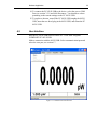
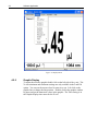
4.2.1
Real Time Display
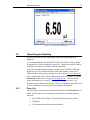
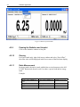
Figure 12 Real Time Display
In Power mode:
The display is updated at 3Hz. The lower window shows the Scale, current
offset value and wavelength. You can change the scale using the quick
arrows beside the scale value. When you change the scale, the acquisition
and all display modes will stop for a few milliseconds.
In Energy mode:
The display is updated at 3Hz. But all data in the statistics are updated at up
to 10 kHz in real time. Single shot measurement is always good. When you
change the scale you might have a false measurement but the next
measurement is accurate. There is no need for “Zero offset” in energy mode
because the 842-E-USB compensates for an analog drift.
The information bar at the bottom shows the scale and wavelength. The
middle box is blank in energy mode. You can change the scale using the
quick arrows beside the scale value. When you change the scale, the
acquisition and all display modes will stop for a few milliseconds.
Software Application
4.2.2
27
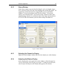
Status Window
In the Status window you can select the channel, scale, wavelength, trigger
level, correction factor, file name, data sampling and external trig option. All
acquisitions and measurements are stopped while you are in the Status
Window. To save your settings, select File/ Save Status. To load your
setting, select File/load status. You must not load a wattmeter status when
using an energy detector or a joulemeter status when using a power detector.
PC-842-E-USB will remember your last Status setting files under File.
Figure 13 Status Window
4.2.3
Selecting the Channel to Display
Right click on the display window and select the channel you wish to display.
4.2.4
Adjusting the Window Display
Select Display/Split with a right click on the window or from the menu bar.
To save your layout, select Layout, save layout. To load your saved layout,
select Layout, load layout or the filename that appears at the bottom.
28
Software Application
Figure 14 Display Menu
4.2.5
Graphic Display
To adjust the real time graphic double click on the left side of the y axis. The
X-Axis minimum and maximum settings are only available in the Load File
option. You can use the mouse wheel to zoom in or out. Left click on the
graphic line to change the line position. Double click in the graphic window
to pause and get the numerical values in the graphic. The Time setting is in
the Graphic display time menu for the X axis.
Software Application
29
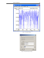
Figure 15 Graphical Display
Figure 16 Graphical Display Settings
30
Software Application
4.2.6
Graphic Mode Option After Opening a File Using Load File
Menu
In the Status Menu, Select a file name for the file to save or to view.
To adjust the graphic axis, double click on the left side of the Y axis.
Deselect the Auto mode to enter the axis values. You can also use the mouse
wheel to zoom in or out. You can zoom the X axis using the mouse wheel
while holding the Shift key. Left click on the graphic to change the line Y
position. If you are zooming the X axis, you can Left click on the graphic
and move the center X position. Double click in the graphic window to get
the numerical values in the graphic.
To zoom the Y axis
To zoom the X axis in the Load File option
4.2.7
Restarting the Lineplot, Statistics, and Histogram
Each window is independent. You can clear each window or use the “Clear
All” menu. You can use a Right-click in the Window to select “Clear” or
“CLEAR ALL”. When you select Clear the Graphic, histogram and statistic
restart.
Software Application
31
Figure 17 Clear and Clear All options
4.2.8
Data Acquisition
To start an acquisition you have to enter the file name in the status menu and
select Acquisition/Channel. A recording message will appear on the bottom
of the screen while recording. To stop an acquisition, reselect
Acquisition/Channel #. The scale’s quick arrows on the real time display are
unavailable during an acquisition. If you do not select a directory, all save
files will be in C:\Program Files\Newport\842-E-USB.
32
Software Application
Figure 18 Data Acquisition Mode
4.2.9
Pausing the Statistics and Lineplot
Click on the Statistics window or line plot.
4.2.10
Zeroing
For Power heads only, right click in any window and select “Zero Offset”,
the offset value will be displayed in the lower center of the Real time display.
4.2.11
Ratio Measurement
In energy mode, the ratio is made with the last received measure to the 842E-USB. Ratio mode doesn’t work if you have a power head and an energy
head.
Example:
Laser value channel #1
10 J
No pulse
8J
12J
Laser value channel #2
5J
2J
No pulse
4J
Results CH1/CH2
2
5
4
3
Software Application
33
Figure 19 Ratio Measurement
4.2.12
Detecting Missing Laser Pulses
The 842-E-USB will detect the missing laser pulses using the External
Trigger and the Histogram Display.
Step1: Connect the External trigger of your Laser to the External trigger of
the 842-E-USB using the BNC connector.
Step2: Select the External trigger from the Status Window.
Step3: Select the Histogram Display in the Display Menu.
34
Software Application
Step4: Start your laser and place you Cursor on the left x-axis, the upper
corner of the histogram will show the number of pulse that are missed. You
can reset the histogram using the clear command.
Software Application
5
Software Installation
5.1
Recommended Specifications of PC
35
Basic functions work well on PCs dated 2004 and later. If you want to
measure higher than 1 kHz and/or display the 3D histogram you have to have
a computer and a graphics card like a Intel core 2 CPU 6420 2.13 Ghz, 4 of
ram and a Nvidia Geforce 7300 LE or better.. If you want to be sure to get
all points and you have a laser frequency above 1 kHz, do not run other
programs at the same time. If you want a very accurate frequency
measurement and average power in energy mode do not run the 3D graphic
display. The supported operating systems are Windows XP, window 7 and
Vista.
In statistics mode the frequency measurement resets itself after the pulse
number reaches the number of pulses set in the Status menu. If you want the
reset to occur less frequently, set a very large number. In order to have a
precise frequency measurement above 1 kHz set the Latency Timer to 1 ms in
USB Advanced Settings. To access the Latency timer menu, in the Device
Manager click Start → Settings → Control Panel → System → Device
Manager.
36
Software Application
Go to USB port properties, Select Port parameters and select Advanced.
Software Application
5.2
Installation And Communication
5.2.1
Installation of Application Software
37
The 842-E-USB is not required for the PC 842-E-USB software installation;
however, it is fine as well if it is connected. Ensure that the 842-E-USB is
connected to the USB port when you are ready to run the PC 842-E-USB
software.
Connect the 842-E-USB USB port, located on the rear panel of the
instrument (see Figure 8), to the host device serial connector using the proper
cable. The 842-E-USB comes with a standard USB cable. You must install
the USB drivers.
5.2.2
Installation of USB drivers for WindowsTM
Plug the 842-E-USB into a USB port on the PC. If the PC supports USB 1.1,
Windows detects the new device and prompts you for the software drivers. A
window that says Found New Hardware – USB Device opens and after
several seconds to a minute the Found New Hardware Wizard appears.
Insert the USB driver’s CD-ROM if you have not already done so.
Cancel the wizard and execute the Auto installer, “USB driver installer-R2”
which can be found in the USB Driver folder on the CD-ROM.
At the end of this process, a new serial COM port is added to the list of
communication ports. It may be used as any other serial port. You will need
to know the COM port number to set up the serial connection to the 842-EUSB.
5.3
Setting Up Communication to 842-E-USB
5.3.1
Verifying COM Port
To verify the USB installation and find the COM port number click:
Start → Settings → Control Panel → System → Device Manager
Scroll down to Ports (COM & LPT) and double click that line. One of the
options should be
USB-to-Serial (COM#)
Note the COM port number. You need it for the next step.
5.3.2
Installation of the PC Software
Download PC 842-E-USB from the internet, www.newport.com, in the
Download section. Execute the downloaded file by double-clicking it, or, if
the internet browser has the option of executing the file, execute it from the
38
Software Application
current location on the website. Follow the installation procedure as
prompted by the software until it is completed.
5.3.3
Running the Software
5.3.3.1
Start the software application
Ensure that the 842-E-USB is connected to the PC 842-E-USB by either
using the USB cable. Verify the COM port to ensure a proper connection.
Start the PC 842-E-USB by clicking Start > Programs > Newport > PCinterface(842-E-USB) menu.
5.3.3.2
Ensure that the correct COM port is selected
Ensure that the correct COM port is selected in the Status Info Section of the
Front Panel. If the PC 842-E-USB cannot communicate with the 842-EUSB, an error message such as ”Could not communicate with device, please
verify connections” is displayed in the Notification section of the Front
Panel, right next to the flashing light (indicating an error). You must remake
the connection if you change the physical connection or the COM port.
5.3.3.3
Exit the software application
To save some important PC 842-E-USB settings, exit using the File > Exit
menu or the Ctrl-F4 hotkey. PC 842-E-USB.
5.3.4
Connecting 842-E-USB
You may use any serial communications software that you are familiar with.
Our instructions are for HyperTerminal because it is widely available on PCs
with Windows. Click:
Start → Programs → Accessories → Communications →
HyperTerminal
To save communication settings, enter a name for the connection. In the drop
down menu “Connect using” select the COM port that the USB driver was
installed on (Section 3.2.1). Click OK.
Input the following settings into the communications parameter window that
appears next.
Bits per second
921600
Data bits
8
Parity
None
Stop bits
1
Flow control
None
Software Application
39
Click OK to begin entering serial commands in the HyperTerminal window.
5.3.5
Echo On/Off
The commands you type do not appear in the HyperTerminal window, unless
you set the HyperTerminal up to do so. Only the response from the 842-EUSB is displayed. If you prefer to see the commands you are typing, on the
HyperTerminal window click the File menu and execute the following
sequence:
File → Properties → Settings (tab) → ASCII setup → select “Echo
typed characters locally” → OK
5.3.6
Testing Connection
In the HyperTerminal window type *VER, press ENTER. If the response
you receive tells you the version of your 842-E-USB, you are successfully
connected and ready for serial command action.
5.3.7
HyperTerminal Setting Shortcut
When you end the session, HyperTerminal asks you if you want to save your
settings. To avoid re-entering the communication parameters, save them by
clicking yes. The next time you execute the string of commands shown in
section 3.2.2 above, the name of your session will appear after
HyperTerminal. Clicking on the session name opens the connection using
the saved settings. To avoid re-entering the string of commands, put a
shortcut to this file on your desktop:
Find the file name, right click on it and select Shortcut in the drop down
menu.
6
Communication Command
Reference
6.1
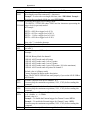
Command Description
6.1.1
Command Glossary
The star (*) is part of each command.
*AT1x /
*AT2x
*CA1 /
*CA2
*CS1 /
*CS2
*AN1x /
*AN2x
To set the Attenuator to Channel 1 or 2
x= 0 = disable, x = 1= enable
Default value is 0.
Example: Enter *AT10 to disable the attenuator for Channel 1.Example: Enter
*AT21 to enable the attenuator for Channel 2.
To Send the data points of Channel 1 or 2 through the serial port at the
frequency of a laser for an Energy head or at 100Hz for a power head.
Output in ASCII mode is:
Wattmeter : 6 digit resolution in Watt
Example:
1:0.001101 : 1.1001 mW on channel 1.
2:100.231 : 100.231 Watts on channel 2.
Energy Mode: 4 digits in scientific notation.
2:8.808e-07 : 0.8808 uJ on channel 2
If you have a repetition rate higher than the ASCII specification, the monitor
sends you an error message. If it does, try sending the *SS100x command to
ignore some laser pulses.
By default the monitor is set in binary mode. To set the ASCII mode, send the
serial commands *SS1001 for channel 1 or *SS2001 for channel 2.
To end/exit the *CA1 or *CA2 mode.
For Power heads only. To set the Anticipation for Channel 1 or 2.
x= 0 = disable, x = 1= enable
Default value is 1.
Example : Enter *AT10 to disable the anticipation for Channel 1.
Example : Enter *AT21 to enable the anticipation for Channel 2.
Appendix A
*RST
*PW1 /
*PW2
To reset the device. The monitor will read the head’s EEprom again.
To set the Wavelength for Channel 1 or 2.
Wavelength correction command (5+ characters).
Example : To select the wavelength 1064 nm, enter *PW101064. Example :
To select the wavelength 10600 nm, enter*PW110600.
*TL10002 To modify the trigger level in energy mode
/
*TL1XXXX / *TL2XXXX where XXXX are four characters representing the
*TL20002 trigger level (in percent) needed.
for example :
XXXX = 0002 for a trigger level of 2%
XXXX = 00.5 for a trigger level of 0.5 %
XXXX = 11.4 for a trigger level of 11.4%
XXXX = 0050 for a trigger level of 50%
*VER
*ST1/
*ST2
*SSX000
Note : the "." is indeed a character
To display the version of the software.
To display information about current status.
See table 1
To set to Binary or ASCII mode.
Example:
*SS1000: Binary Mode for channel 1
*SS1001: ASCII mode sends All points
*SS1002: ASCII mode sends 1 out of 2 points
*SS1003: ASCII mode sends 1 out of 3 points
*SS1999: ASCII mode sends 1 out of 999 points ( 999 is the maximum )
*SS2001: ASCII mode sends All points for channel 2
*SU1 /
*SU2
*SD1 /
*SD2
*ET1x /
*ET2x
*EM1x /
Default value is 0 (Binary mode)
Contact Newport for Binary mode description.
Note: The PC-842-E-USB will not work properly if you set the 842-E-USB to
ASCII mode.
To make a physical scale up for channel 1 or 2.
You must stop the continuous acquisition (*CS1, *CS2), before sending this
command.
To make a physical scale down for channel 1 or 2.
You must stop the continuous acquisition (*CS1, *CS2), before sending this
command.
To Set the External Trigger for Channel 1 or 2.
x= 0 = disable, x = 1= enable
Default value is 0.
Example : To disable the External trigger for Channel 1 enter *ET10 .
Example : To enable the External trigger for Channel 2 enter *ET21 .
You must stop the continuous acquisition (*CS1, *CS2), before sending this
command.
For Power heads only. To set the energy Mode to Channel 1 or 2.
42
Appendix A
*EM2x
*NMV
*NMQ
*NA1 /
*NA2
*SN1 /
*SN2
*CV1 /
*CV2
*VNM
*VNP
*RG1 /
*RG2
x= 0 = disable, x = 1= enable
Default value is 0.
Example : To disable the Energy mode for Channel 1 enter *EM10 .
Example : To enable the Energy mode for Channel 2 enter *EM21.
You must stop the continuous acquisition (*CS1, *CS2), before sending this
command.
Active the acknowledge mode
This function tells the 842-E-USB to send an ACK after each serial commands
received
The PC-842-E-USB will not work if you send this command and don’t send
the *NMQ, *RST or don’t cycle the power before trying to make a connection.
Deactivate the *NMV mode (Default mode)
Return the detector name for channel 1 or 2.
Return the detector serial number for channel 1 or 2.
Return the last 842-E-USB measurement for channel 1 or 2. This mode is only
available in ASCII mode.
For joulemeter mode it will be the last laser pulse value, for wattmeter mode it
will be the last measurement taken.
Example to get only 1 value
Set the ASCII mode for channel 1 or 2.
*SS1001 or *SS2001
Set the scale for channel 1 or 2.
*SC1XX or *SC2XX, where XX is the scale you want in decimal.
Set the poling mode
* VNM
Start the internal acquisition
*CA1 or *CA2
Request 1 Value for channel 1 or 2.
*CV1 or *CV2
Activate the *VNP polling mode, This mode is only available in ASCII mode
Deactivate the *CV1 and *CV2 mode (Default mode at power up)
Return the current minimum and maximum range for channel 1 or 2.
The information is coded
The fist 5 byte is the identifier
00000: minimum scale.
00001: maximum scale.
10000: End of transmission.
The last 4 bytes are the scale coded in hex value, use the scale table bellow to
determine the scale
Example
After a RG1 you will receive
“:000000013
:00001001A
:100000000”
What it means
Appendix A
*SC1xx /
*SC2xx
:000000013 : is the minimum scale 13 hex = 19 = 3m
:00001001A : is the maximum scale 1A hex=26=10 (Watt or Joule)
:100000000 : End of transmission.
To set the Scale to Channel 1 or 2.
xx = See Table bellow, you send the value for the scale in decimal, but when
making a status request the 842-E-USB send it in Hexadecimal.
You must stop the continuous acquisition (*CS1, *CS2), before sending this
command.
Scale
1p
3p
10p
30p
100p
300p
1n
3n
10n
30n
100n
300n
1u
3u
10u
30u
100u
300u
1m
3m
10m
30m
100m
300m
1
3
10
30
100
300
1k
3k
10k
30k
100k
300k
xx
00
01
02
03
04
05
06
07
08
09
10
11
12
13
14
15
16
17
18
19
20
21
22
23
24
25
26
27
28
29
30
31
32
33
34
35
1 picowatt or picojoule
3 picowatts or picojoules
10 picowatts or picojoules
30 picowatts or picojoules
100 picowatts or picojoules
300 picowatts or picojoules
1 nanowatt or nanojoule
3 nanowatts or nanojoules
10 nanowatts or nanojoules
30 nanowatts or nanojoules
100 nanowatts or nanojoules
300 nanowatts or nanojoules
1 microwatt or microjoule
3 microwatts or microjoules
10 microwatts or microjoules
30 microwatts or microjoules
100 microwatts or microjoules
300 microwatts or microjoules
1 milliwatt or millijoule
3 milliwatts or millijoules
10 milliwatts or millijoules
30 milliwatts or millijoules
100 milliwatts or millijoules
300 milliwatts or millijoules
1 Watt or Joule
3 watts or joules
10 watts or joules
30 watts or joules
100 watts or joules
300 watts or joules
1 kilowatt or kilojoule
3 kilowatts or kilojoules
10 kilowatts or kilojoules
30 kilowatts or kilojoules
100 kilowatts or kilojoules
300 kilowatts or kilojoules
44
Appendix A
1meg
3meg
10meg
30meg
100meg
300meg
36
37
38
39
40
41
1 megawatt or megajoule
3 megawatts or megajoules
10 megawatts or megajoules
30 megawatts or megajoules
100 megawatts or megajoules
300 megawatts or megajoules
Status definitions
*ST1: Status for Channel #1
*ST2: Status for Channel #2
Hex Value
:000000428
Address (first
5 bytes)
0000
4 last
bytes
0428
:000010013
:00002002B
00001
00002
0013
002B
:000030000
:000040000
00003
00004
0000
0000
:000050001
00005
00001
:000060000
00006
0000
:000070000
00007
0000
:100000000
End of file
0000
Definition
In this example
Wavelength in hex value
1064
Current Scale in hex value
Trig Level in hex value/
20.48
Reserved
Attenuator setting
0000 = no attenuator
0001= with attenuator
External trigger setting
0000 = off
0001 = on
Anticipation
0000 = off
0001 = on
Energy mode for power
head
0000 = off
0001 = on
19= 3 mJ
43/20.48= 2.1%
No Attenuator
On
Off
Off
Appendix A
7
Maintenance and Service
CAUTION
There are no user serviceable parts inside the 842-E-USB Optical
Power/Energy Meter. Work performed by persons not authorized
by Newport Corporation will void the warranty.
Calibration accuracy is warranted for a period of 1 year. After 1
year, the unit should be returned to Newport Corporation for
recalibration and NIST trace ability re-certification.
7.1
Enclosure Cleaning
WARNING
Before cleaning the enclosure of the 842-E-USB, the USB cable
must be removed.
The enclosure should only be cleaned with isopropyl alcohol or a mild soapy
water solution applied to a damp lint-free cloth.
7.2
USB connector for 842-E-USB
The 842-E-USB has a USB type B port. When it is connected to a PC it
emulates a standard serial port. It has a simple interface so that it is easy to
design software for. The 842-E-USB can function using only the USB port
power.
7.3
Free Software Upgrade
Keep up to date with the latest version of 842-E-USB software, including
new features and options. As new and improved versions of the device's
firmware are created, it is in your best interest to update your 842-E-USB.
The latest device firmware can be downloaded from the Newport website.
The update must be done using the USB port. An update through the
Ethernet port will cause the 842-E-USB to be unusable and will need to be
reprogrammed by the manufacturer.
46
Appendix A
Access our website at www.newport.com. Go to the Downloads tab. Find
the file that corresponds to your 842-E-USB in the Downloads section and
follow our simple, easy-to-use instructions.
7.4
Obtaining Service
Model 842-E-USB contains no user serviceable parts. To obtain information
regarding factory service, contact Newport Corporation or your Newport
representative. Please have the following information available:
Instrument model number (on the rear panel)
Instrument serial number (on rear panel)
Description of the problem.
If the instrument is to be returned to Newport Corporation, you will be given
a Return Number, which you should reference in your shipping documents.
Please fill out a copy of the service form, located on the following page, and
have the information ready when contacting Newport Corporation. Return
the completed service form with the instrument.
Appendix A
7.5
Service Form
Newport Corporation
U.S.A. Office: 800-222-6440
FAX: 949/253-1479
Name _______________________________
Return Authorization #__________________
(Please obtain RA# prior to return of item)
Company ________________________________________________________________________
(Please obtain RA # prior to return of item)
Address ________________________________ ____________________Date _________________
Country _______________________ Phone Number ______________________________________
P.O. Number ___________________ FAX Number _______________________________________
Item(s) Being Returned:
Model # _______________________ Serial # __________________________
Description _______________________________________________________________________
Reason for return of goods (please list any specific problems):
48
Appendix A
8
8.1
Appendix A – Attenuator /
Diffuser Calibration Procedure
Introduction
Newport’s 818E-Series Energy Detectors are not normally calibrated with the
818E-DA-25/50 and 818E-DG-25/50 Attenuator/Diffusers. Therefore, to
achieve accurate measurements, the user must perform a calibration. The
calibration procedure is relatively simple. You will first make a measurement
without the attenuator, and then with the attenuator. The ratio of these two
measurements will be your correction factor.
Using the 842-PE Power & Energy Meter, make sure that the Attenuator
setting in the Control menu is not checked. That is, it must be off.
Otherwise, accessing the wavelength correction (Settings / Corrections
menus) would be impossible.
8.2
Procedure
Step 1: Set up your energy detector to measure the energy of your pulsed
laser. If you are working at a wavelength other than the calibrated
wavelength, first make the proper correction by following the procedures
given in Section 2.3.3.1 - Wavelength Setting. Make sure that the energy
level is below the detector’s damage threshold and your laser still has good
stability.
Step 2: Apply energy for a few minutes to warm up the detector. This will
reduce any thermal bias.
Step 3: Measure the energy level without the attenuator. To reduce random
uncertainty you should average a number of shots. We recommend at least
one hundred shots. This should reduce random errors by a factor of 10
(square root of N, assuming a Gaussian distribution).
Step 4: Install the attenuator. Without changing the laser settings measure
the energy level by averaging the same number of shots. All laser settings
must be the same as Step 3 (including beam size and position on the
detector).
Appendix A
Step 5: Repeat the first measurement (Step 3) to make sure that nothing has
changed during the procedure that would invalidate the calibration. A change
larger than the uncertainty of your measurements means that something in the
laser or environment has changed. You can either add this to your ±
uncertainty when you use the attenuator or try to stabilize the laser and
environment and begin again with Step 3.
The correction multiplier for the 842-E-USB will be given by:
Tf
Reading without attenuator
Reading with attenuator
(no units)
Now use this calibration factor for the “Attenuator/Diffuser” when using it at
the wavelength established in Step 1.
9
Appendix B – Disassembly
Instructions
NOTE
These disassembly instructions are intended only for recycling at the end of the
product lifetime.
For troubleshooting or servicing, users should contact the local Newport Corporation
representative. There are no user serviceable parts inside the equipment.
Attempting to self-service the unit will void the warranty.
9.1
Recycling and Separation Instruction
This section is used by the recycling center when the monitor is at the end of
its life. Breaking the calibration seal or opening the monitor will void the
842-E-USB warranty.
The complete Monitor contains
1 Monitor
1 USB cable
1 Instruction manual
1 Calibration certificate
1 Software cdrom
9.2
Separation
Paper: Manual and certificate
Aluminum: Monitor enclosure.
Printed circuit board: inside the monitor.
9.3
Disassembly
To open the monitor:
Remove all the screws on both sides of the monitor:
Remove the PCB by sliding it out of the enclosure.
10
Appendix C – Avoiding COM
Port Increment
This procedure is to avoid the COM port to keep incrementing for new
devices. Please note that the com port will change if you plug the USB cable
in a different location on your PC, but it will not increment with another 842E-USB-2 in the same USB port.
10.1
Procedure
10.1.1
Installing FT-PROG.exe Program
Connect only 1 device at a time. To run the application, follow the procedure
as described below.
1. Install the USB drivers from the Newport web site.
http://www.Newport.com/en/downloads.htm
2. Download the latest version of FT_PROG from the Utilites section of
the FTDI website.
http://www.ftdichip.com/Resources/Utilities.htm
3. Unzip all files from the .zip folder that you have downloaded.
4. FT_PROG requires Microsoft .NET Framework 2.0 installed on your
system to run. This can be obtained from the Microsoft website:
http://www.microsoft.com/downloads/details.aspx?FamilyID=0856EACB
-4362-4B0D-8EDD-AAB15C5E04F5&displaylang=en
Download and follow the wizard for installing .NET 2.0 if you do not
have this already installed on your system.
5. To run the application double click on the FT_PROG.exe icon.
10.1.2
Running FT-PROG.exe Program
1. Click ‘Scan and Parse’, under ‘Devices’ menu.
52
2. Unselect the Serial USB UART in the USB_String_Descriptor
3. Select ‘Program’ under ‘Devices’ menu.
4. Select the Device in the Device list, Click on Program and close the
FT_PROG software. Unplug and replug the USB device.
Internal #103175 Rev. A
54
End User License Agreement for Embedded Software Components
You have acquired a device (“DEVICE”) that includes software licensed by Newport Corporation (“Newport”) from an affiliate of Microsoft
Corporation (“MS”). Those installed software products of MS origin, as well as associated media, printed materials, and “online” or electronic
documentation (“SOFTWARE”) are protected by international intellectual property laws and treaties. Manufacturer, MS and its suppliers
(including Microsoft Corporation) own the title, copyright, and other intellectual property rights in the SOFTWARE. The SOFTWARE is
licensed, not sold. All rights reserved.
This End User License Agreement (“EULA”) is valid and grants the end-user rights ONLY if the SOFTWARE is genuine Certificate of
Authenticity for the SOFTWARE is included. For more information on identifying whether your software is genuine, please see
http://www.microsoft.com/piracy/howtotell.
IF YOU DO NOT AGREE TO THIS EULA, DO NOT USE THE DEVICE OR COPY THE SOFTWARE. INSTEAD, PROMPTLY
CONTACT NEWPORT FOR INSTRUCTIONS ON RETURN OF THE UNUSED DEVICES(S) FOR A REFUND. ANY USE OF THE
SOFTWARE, INCLUDING BUT NOT LIMITED TO USE ON THE DEVICE, WILL CONSTITUTE YOUR AGREEMENT TO THIS
EULA (OR RATIFICATION OF ANY PREVIOUS CONSENT).
GRANT OF SOFTWARE LICENSE. This EULA grants you the following license:
You may use the SOFTWARE only on the DEVICE.
Restricted Functionality. You are licensed to use the SOFTWARE to provide only the limited functionality (specific tasks or processes)
for which the DEVICE has been designed and marketed by Newport. This license specifically prohibits any other use of the software
programs or functions, or inclusion of additional software programs or functions that do not directly support the limited functionality on the
DEVICE. Notwithstanding the foregoing, you may install or enable on a DEVICE, systems utilities, resource management or similar
software solely for the purpose of administration, performance enhancement and/or preventive maintenance of the DEVICE.
If you use the DEVICE to access or utilize the services or functionality of Microsoft Windows Server products (such as Microsoft Windows
Server 2003), or use the DEVICE to permit workstation or computing devices to access or utilize the services or functionality of Microsoft
Windows Server products, you may be required to obtain a Client Access License for the DEVICE and/or each such workstation or
computing device. Please refer to the end user license agreement for your Microsoft Window Server product for additional information.
NOT FAULT TOLERANT. THE SOFTWARE IS NOT FAULT TOLERANT. NEWPORT HAS INDEPENDENTLY DETERMINED
HOW TO USE THE SOFTWARE IN THE DEVICE, AND MS HAS RELIED UPON NEWPORT TO CONDUCT SUFFICIENT
TESTING TO DETERMINE THAT THE SOFTWARE IS SUITABLE FOR SUCH USE.
NO WARRANTIES FOR THE SOFTWARE. The SOFTWARE is provided “AS IS” and with all faults. THE ENTIRE RISK AS TO
SATISFACTORY QUALITY, PERFORMANCE, ACCURACY, AND EFFORT (INCLUDING LACK OF NEGLIGENCE) IS WITH
YOU. ALSO, THERE IS NO WARRANTY AGAINST INTERFERENCE WITH YOUR ENJOYMENT OF THE SOFTWARE OR
AGAINST INFRINGEMENT. IF YOU HAVE RECEIVED ANY WARRANTIES REGARDING THE DEVICE OR THE
SOFTWARE, THOSE WARRANTIES DO NOT ORIGINATE FROM, AND ARE NOT BINDING ON, MS.
No Liability for Certain Damages. EXCEPT AS PROHIBITED BY LAW, MS SHALL HAVE NO LIABILITY FOR ANY
INDIRECT, SPECIAL, CONSEQUENTIAL OR INCIDENTAL DAMAGES ARISING FROM OR IN CONNECTION WITH
THE USE OR PERFORMANCE OF THE SOFTWARE. THIS LIMITATION SHALL APPLY EVEN IF ANY REMEDY FAILS
OF ITS ESSENTIAL PURPOSE. IN NO EVENT SHALL MS BE LIABLE FOR ANY AMOUNT IN EXCESS OF U.S. TWO
HUNDRED FIFTY DOLLARS (U.S. $250.00).
Restricted Uses. The SOFTWARE is not designed or intended for use or resale in hazardous environments requiring fail-safe performance,
such as in the operation of nuclear facilities, aircraft navigation or communication systems, air traffic control, or other devices or systems in
which a malfunction of the SOFTWARE would result in foreseeable risk of injury or death to the operator of the device or system, or to
others.
Limitations on Reverse Engineering, Decompilation, and Disassembly. You may not reverse engineer, decompile, or disassemble the
SOFTWARE, except and only to the extent that such activity is expressly permitted by applicable law notwithstanding this limitation.
SOFTWARE as a Component of the DEVICE – transfer. This license may not be shared, transferred to or used concurrently on
different computers. The SOFTWARE is licensed with the DEVICE as a single integrated product and may only be used with the
DEVICE. If the SOFTWARE is not accompanied by a DEVICE, you may not use the SOFTWARE. You may permanently transfer all of
your rights under this EULA only as part of a permanent sale or transfer of the DEVICE, provided you retain no copies of the SOFTWARE.
If the SOFTWARE is an upgrade, any transfer must also include all prior versions of the SOFTWARE. This transfer must also include the
Certificate of Authenticity label. The transfer may not be an indirect transfer, such as a consignment. Prior to the transfer, the end user
receiving the SOFTWARE must agree to all the EULA terms.
Consent to Use of Data. You agree that MS, Microsoft Corporation and their affiliates may collect and use technical information gathered
in any manner as part of product support services related to the SOFTWARE. MS, Microsoft Corporation and their affiliates may use this
information solely to improve their products or to provide customized services or technologies to you. MS, Microsoft Corporation and their
affiliates may disclose this information to others, but not in a form that personally identifies you.
Links to Third Party Sites. You may link to third party sites through the use of the SOFTWARE. The third party sites are not under the
control of MS or Microsoft Corporation, and MS or Microsoft are not responsible for the contents if any third party sites, any links
contained in third party sites, or any changes or updates to third party sites. MS or Microsoft Corporation is not responsible for webcasting
or any other form of transmission received from any third party sites. MS or Microsoft Corporation are providing these links to third party
sites to you only as a convenience, and the inclusion of any link does not imply an endorsement by MS or Microsoft Corporation of the
third party site.
Notice Regarding Security. To help protect against breaches of security and malicious software, periodically back up your data and
system information, use security features such as firewalls, and install and use security updates.
No Rental/Commercial Hosting. You may not rent, lease, lend or provide commercial hosting services with the SOFTWARE to others.
Separation of Components. The SOFTWARE is licensed as a single product. Its component parts may not be separated for use on more
than one computer.
Additional Software/Services. This EULA applies to updates, supplements, add-on components, product support services, or Internetbased services components (“Supplemental Components”), of the SOFTWARE that you may obtain from Newport, MS, Microsoft
Corporation or their subsidiaries after the date you obtain your initial copy of the SOFTWARE, unless you accept updated terms or another
agreement governs. If other terms are not provided along with such Supplemental Components and the Supplemental Components are
provided to you by MS, Microsoft Corporation or their subsidiaries then you will be licensed by such entity under the same terms and
conditions of this EULA, except that (i) MS, Microsoft Corporation or their subsidiaries providing the Supplemental Components will be
the licensor with respect to such Supplemental Components in lieu of Newport for the purposes of the EULA, and (ii) TO THE
MAXIMUM EXTENT PERMITTED BY APPLICABLE LAW, THE SUPPLEMENTAL COMPONENTS AND ANY (IF ANY)
SUPPORT SERVICES RELATED TO THE SUPPLEMENTAL COMPONENTS ARE PROVIDED AS IS AND WITH ALL FAULTS.
ALL OTHER DISCLAIMERS, LIMITATION OF DAMAGES, AND SPECIAL PROVISIONS PROVIDED BELOW AND/OR
OTHERWISE WITH THE SOFTWARE SHALL APPLY TO SUCH SUPPLEMENTAL COMPONENTS. MS, Microsoft Corporation or
their subsidiaries reserve the right to discontinue any Internet-based services provided to you or made available to you through the use of
the SOFTWARE.
Recovery Media. If SOFTWARE is provided by Newport on separate media and labeled “Recovery Media” you may use the Recovery
Media solely to restore or reinstall the SOFTWARE originally installed on the DEVICE.
Backup Copy. You may make one (1) backup copy of the SOFTWARE. You may use this backup copy solely for your archival purposes
and to reinstall the SOFTWARE on the DEVICE. Except as expressly provided in this EULA or by local law, you may not otherwise make
copies of the SOFTWARE, including the printed materials accompanying the SOFTWARE. You may not loan, rent, lend or otherwise
transfer the backup copy to another user.
End User Proof of License. If you acquired the SOFTWARE on a DEVICE, or on a compact disc or other media, a genuine Microsoft
“Proof of License”/Certificate of Authenticity label with a genuine copy of the SOFTWARE identifies a licensed copy of the SOFTWARE.
To be valid, the label must be affixed to the DEVICE, or appear on Newport’s software packaging. If you receive the label separately other
than from Newport, it is invalid. You should keep the label on the DEVICE or packaging to prove that you are licensed to use the
SOFTWARE.
Product Support. Product support for the SOFTWARE is not provided by MS, Microsoft Corporation, or their affiliates or subsidiaries.
For product support, please refer to the Newport support number provided in the documentation for the DEVICE. Should you have any
questions concerning this EULA, or if you desire to contact Newport for any other reason, please refer to the address provided in the
documentation for the DEVICE.
Termination. Without prejudice to any other rights, Newport may terminate this EULA if you fail to comply with the terms and conditions
of this EULA. In such event, you must destroy all copies of the SOFTWARE and all of its component parts.
Export Restrictions. You acknowledge that SOFTWARE is subject to U.S. and European Union export jurisdiction. You agree to comply
with all applicable international and national laws that apply to the SOFTWARE, including the U.S. Export Administration Regulations, as
well as end-user, end-use and destination restrictions issued by U.S. and other governments. For additional information, see
http://www.microsoft.com/exporting/.
Newport Corporation
Worldwide Headquarters
1791 Deere Avenue
Irvine, CA 92606
(In U.S.): 800-222-6440
Tel: 949-863-3144
Fax: 949-253-1680
Internet: [email protected]
Visit Newport Online at: www.newport.com
Newport Corporation, Irvine, California; Evry and Beaune-La-Rolande, France have all been certified
compliant with ISO 9001 by the British Standards Institution. Mountain View, California is DNV certified.