1
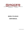
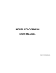
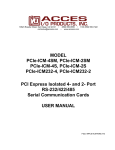
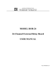
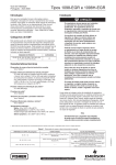
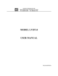
10623 Roselle Street, San Diego, CA 92121 • (858) 550-9559 • FAX (858) 550-7322
[email protected] • www.accesio.com
MODELS PCIe-COM232-8
and PCIe-COM232-4
PCI Express Multi-Port Low Profile Serial
Communications Cards
USER MANUAL
FILE: MPCIe-COM232-8.A1n
Notice
The information in this document is provided for reference only. ACCES does not assume any liability arising
out of the application or use of the information or products described herein. This document may contain or
reference information and products protected by copyrights or patents and does not convey any license under
the patent rights of ACCES, nor the rights of others.
IBM PC, PC/XT, and PC/AT are registered trademarks of the International Business Machines Corporation.
Printed in USA. Copyright 2009 by ACCES I/O Products Inc, 10623 Roselle Street, San Diego, CA 92121. All
rights reserved.
WARNING!!
ALWAYS CONNECT AND DISCONNECT YOUR FIELD CABLING WITH THE
COMPUTER POWER OFF. ALWAYS TURN COMPUTER POWER OFF
BEFORE INSTALLING A CARD. CONNECTING AND DISCONNECTING
CABLES, OR INSTALLING CARDS INTO A SYSTEM WITH THE
COMPUTER OR FIELD POWER ON MAY CAUSE DAMAGE TO THE I/O
CARD AND WILL VOID ALL WARRANTIES, IMPLIED OR EXPRESSED.
2
PCIe-COM232-8 User Manual
Warranty
Prior to shipment, ACCES equipment is thoroughly inspected and tested to applicable specifications. However,
should equipment failure occur, ACCES assures its customers that prompt service and support will be available.
All equipment originally manufactured by ACCES which is found to be defective will be repaired or replaced
subject to the following considerations.
Terms and Conditions
If a unit is suspected of failure, contact ACCES' Customer Service department. Be prepared to give the unit
model number, serial number, and a description of the failure symptom(s). We may suggest some simple tests
to confirm the failure. We will assign a Return Material Authorization (RMA) number which must appear on the
outer label of the return package. All units/components should be properly packed for handling and returned
with freight prepaid to the ACCES designated Service Center, and will be returned to the customer's/user's site
freight prepaid and invoiced.
Coverage
First Three Years: Returned unit/part will be repaired and/or replaced at ACCES option with no charge for labor
or parts not excluded by warranty. Warranty commences with equipment shipment.
Following Years: Throughout your equipment's lifetime, ACCES stands ready to provide on-site or in-plant
service at reasonable rates similar to those of other manufacturers in the industry.
Equipment Not Manufactured by ACCES
Equipment provided but not manufactured by ACCES is warranted and will be repaired according to the terms
and conditions of the respective equipment manufacturer's warranty.
General
Under this Warranty, liability of ACCES is limited to replacing, repairing or issuing credit (at ACCES discretion)
for any products which are proved to be defective during the warranty period. In no case is ACCES liable for
consequential or special damage arriving from use or misuse of our product. The customer is responsible for all
charges caused by modifications or additions to ACCES equipment not approved in writing by ACCES or, if in
ACCES opinion the equipment has been subjected to abnormal use. "Abnormal use" for purposes of this
warranty is defined as any use to which the equipment is exposed other than that use specified or intended as
evidenced by purchase or sales representation. Other than the above, no other warranty, expressed or implied,
shall apply to any and all such equipment furnished or sold by ACCES.
3
PCIe-COM232-8 User Manual
TABLE OF CONTENTS
Chapter 1: Introduction ..................................................................................................................... 5
Features............................................................................................................................................. 5
Applications...................................................................................................................................... 5
Functional Description .................................................................................................................. 5
Figure 1-1: Block Diagram ........................................................................................................ 6
Ordering Guide ................................................................................................................................ 6
Model Options.................................................................................................................................. 7
Optional Accessories..................................................................................................................... 7
Special Order.................................................................................................................................... 7
Included with your board .............................................................................................................. 7
Chapter 2: Installation........................................................................................................................ 8
CD Software Installation................................................................................................................ 8
DOS..................................................................................................................................................... 8
Windows ............................................................................................................................................ 8
Linux................................................................................................................................................... 8
Hardware Installation ..................................................................................................................... 9
Figure 2-1: Installed Cards with Stability Bracket Accessories ..................................... 9
Chapter 3: Hardware Details .......................................................................................................... 10
Figure 3-1: Card Dimensions ................................................................................................. 10
Fast RS-232 transceivers (-F) .................................................................................................... 10
Low-profile mounting bracket (-L)............................................................................................ 10
Remote Wake-Up (-W).................................................................................................................. 11
Extended temperature (-T).......................................................................................................... 11
RoHS compliance (-RoHS).......................................................................................................... 11
VHDCI connector........................................................................................................................... 11
Chapter 4: Address Selection........................................................................................................ 12
Chapter 5: Programming................................................................................................................. 13
Sample Programs.......................................................................................................................... 13
Windows COM Utility Program.................................................................................................. 13
Windows Programming............................................................................................................... 13
Baud Rates...................................................................................................................................... 13
Table 5-1: Baud Rate Divisor Values ................................................................................... 13
Chapter 6: Connector Pin Assignments ..................................................................................... 14
Input/Output Connections .......................................................................................................... 14
Table 6-1: Connector Pin Assignments .............................................................................. 14
Figure 6-1: Male DB9 Connector Pin Locations................................................................ 14
VHDCI 68-Pin D-Connector......................................................................................................... 15
Table 6-2: VHDCI 68-Pin Female D-Connector Pin Assignments ................................ 15
Figure 6-2: VHDCI 68-Pin Female D-Connector Pin Locations..................................... 15
Chapter 7: Specifications................................................................................................................ 16
Communications Interface ......................................................................................................... 16
Environmental................................................................................................................................ 16
Customer Comments ....................................................................................................................... 17
4
PCIe-COM232-8 User Manual
Chapter 1: Introduction
The PCI Express Multiport Serial cards were designed for RS232 asynchronous
communications for use in a variety of applications. These boards were designed to offer
compatibility with the PCI Express bus and to be used by system integrators and
manufacturers in the design of industrial and commercial communication systems. The card is
available in 8-port and 4-port versions and is compatible with all popular operating systems.
Each RS232 port is capable of supporting data rates up to 921.6kbps (460.8kbps version is
standard) and implements full modem control signals to ensure compatibility with a wide range
of serial peripherals. Existing serial peripherals can connect directly to the industry standard
DB9M connectors which are provided via an available cable. The board features a x1 lane
PCI Express connector which can be used in any x1, x2, x4, x8, x12 or x16 PCI Express slot.
.
Features
•
•
•
•
•
•
•
•
•
Eight- or four-port PCI Express RS-232 serial communications
Low profile MD1 form factor, MD1 defines the shortest standard card length available
High performance 16C950 class UARTs with 128-byte FIFO for each TX and RX
Supports data communication speeds up to 921.6kbps (standard model 460.8kbps)
+/-15kV ESD protection on all signal pins
Full modem control signals
Software compatible with all operating systems
Plug and Play, no jumpers to configure
6’ breakout cable terminating with industry-standard DB9M connectors
Applications
•
•
•
•
•
•
•
•
•
POS (Point-of-sale) Systems
Gaming Machines
Transportation Stations
Telecommunications
Industrial Automation
ATM (Automated Teller Machine) Systems
Multiple terminal control
Office Automation
Kiosks
Functional Description
These cards feature high performance 16C950 class UARTs which support the complete
register set of the standard 16C550-type devices. The UARTs support operations in 16C450,
16C550 and 16C950 modes. Each port is capable of data communication speeds up to
921.6kbps (standard model up to 460.8kbps) in asynchronous mode and has 128-byte deep
transmit and receive FIFOs to protect against lost data in multitasking operating systems, to
help reduce CPU utilization and to improve data throughput.
5
PCIe-COM232-8 User Manual
The card features a x1 lane PCIe connector which can be used in any available PCIe slot
width. The low profile MD1 form factor allows the card to be installed in small embedded
systems where a standard MD2 low profile card will not fit. The card can be used in both a
standard profile chassis or in a low profile chassis when used with the correct mounting
bracket. Our PCI Express RS-232 cards ship with a standard height PCIe mounting bracket
installed. This bracket also has threaded inserts above and below the VHDCI 68-pin
connector to facilitate installation of the strengthening bracket accessory. The industrialized
strengthening bracket accessory protects against damage to the very high density I/O cardmounted connector when side-to-side tension can occur on the breakout cable.
A crystal oscillator is located on the card. This oscillator permits precise selection of standard
baud rates. Custom baud rates are available on request, please refer to the “Special Order”
paragraph.
Figure 1-1: Block Diagram
Ordering Guide
•
•
•
•
PCIe-COM232-8
PCI Express eight-port RS-232 card with standard height
mounting bracket and a 6’ DB9M breakout cable
PCIe-COM232-8NC PCI Express eight-port RS-232 card with standard height
mounting bracket without cable
PCIe-COM232-4
PCI Express four-port RS-232 card with standard height
mounting bracket and a 6’ DB9M breakout cable
PCIe-COM232-4NC PCI Express four-port RS-232 card with standard height
mounting bracket without cable
6
PCIe-COM232-8 User Manual
Model Options
•
•
•
•
•
-F
-L
-T
-RoHS
-W
Fast RS-232 transceivers (up to 921.6kbps)
Low-profile mounting bracket
Extended Operating Temperature of -40°C to +85°C
RoHS compliant version
Wake-up enable (see Chapter 3: Hardware Details)
Optional Accessories
BRKT-551-SCB
Strengthening bracket
(for use with standard height PCIe bracket only)
ADAP9
Screw terminal adaptor DB9F to 9 screw terminals
ADAP9-2
Screw terminal adaptor with two DB9F connectors and 18
screw terminals
Special Order
Custom baud rates are available upon request. Contact factory with your precise requirement.
Other specials: conformal coating, custom software, RJ-45 connectivity, special breakout
boxes, etc., we will work with you to provide exactly what is required.
Included with your board
The following components are included with your shipment, depending on options ordered.
Please take the time now to ensure that no items are damaged or missing.
•
•
•
•
Eight- or four-port card with standard height mounting bracket
6’ breakout cable to DB9M connectors
Software Master CD
Quick-Start Guide
7
PCIe-COM232-8 User Manual
Chapter 2: Installation
A printed Quick-Start Guide (QSG) is packed with the card for your convenience. If you’ve
already performed the steps from the QSG, you may find this chapter to be redundant and
may skip forward to begin developing your application.
The software is provided with this card on the CD and must be installed onto your hard disk
prior to use. Perform the following steps as appropriate for your operating system.
A complete driver support package is provided including an easy-to-use Windows terminal
program for testing out your COM ports. This simplifies the verification of proper COM port
operating. The card installs as standard COM ports in all operating systems.
A software reference manual is installed as part of the software and support package for this
product. Please refer to this document for extensive information and guidance on software
tools and programming support at your disposal.
CD Software Installation
The following instructions assume the CD-ROM drive is drive “D”. Please substitute the
appropriate drive letter for your system as necessary.
DOS
1.
2.
3.
4.
Place the CD into your CD-ROM drive.
Type B- to change the active drive to the CD-ROM drive.
Type GLQR?JJ- to run the install program.
Follow the on-screen prompts to install the software for this board.
Windows
1. Place the CD into your CD-ROM drive.
2. The system should automatically run the install program. If the install program does not
run promptly, click START | RUN and type BGLQR?JJ, click OK or press -.
3. Follow the on-screen prompts to install the software for this board.
Linux
1. Please refer to linux.htm on the CD-ROM for information on installing under linux.
Note: COM boards can be installed in virtually any operating system. We do support
installation in earlier versions of Windows, and are also likely to support future versions.
8
PCIe-COM232-8 User Manual
Hardware Installation
Caution! * ESD
A single static discharge can damage your card and cause
premature failure! Please follow all reasonable precautions to
prevent a static discharge such as grounding yourself by touching
any grounded surface prior to touching the card.
1.
2.
3.
4.
Do not install the card into the computer until the software has been fully installed.
Turn OFF computer power AND unplug AC power from the system.
Remove the computer cover.
Carefully install the card in an available PCIe expansion slot (you may need to remove a
backplate first).
5. Inspect for proper fit of the card and install and tighten the mounting bracket screw. Make
sure that the card mounting bracket is properly screwed into place and that there is a
positive chassis ground.
6. Install a cable onto the card’s bracket mounted connector
7. If you purchased the optional DB9M breakout cable, you may have also purchased the
connector / cable stabilization bracket, which should be installed at this time
Figure 2-1: Installed Cards with Stability Bracket Accessories
.
8. Replace the computer cover and turn ON the computer.
9. Most computers should auto-detect the card (depending on the operating system) and
automatically finish installing the drivers.
10. Run one of the provided sample programs that was copied to the newly created card
directory (from the CD) to test and validate your installation.
9
PCIe-COM232-8 User Manual
Chapter 3: Hardware Details
There are no user-selectable options for this card, only factory options.
Figure 3-1: Card Dimensions
Fast RS-232 transceivers (-F)
The standard RS-232 transceivers used are capable of speeds up to 460.8kbps which is
adequate in many applications. For this factory option, the board is populated with high-speed
RS-232 transceivers enabling error-free communications at up to 921.6kbps.
Low-profile mounting bracket (-L)
For system designers where space is limited we offer a low profile mounting bracket option.
The strengthening bracket accessory can not be used with this option.
10
PCIe-COM232-8 User Manual
Remote Wake-Up (-W)
The “Remote Wake-Up” factory option is for use in applications where the host computer (the
one this card would be installed in) enters the L2 low-power state where it’s main power is
turned off though VAUX is still applied. When the Ring Indicator is received on serial port
channel A in the L2 power state, Wake-Up is asserted.
Extended temperature (-T)
This factory option is for use in harsh environments and is populated with all-industrial rated
components, specified at a minimum temperature range of -40°C to +85°C.
RoHS compliance (-RoHS)
For international customers and other special requirements, this factory option is available in
RoHS compliant versions.
VHDCI connector
These cards use an Amphenol 68-pin VHDCI (Very High Density Cable Interconnect)
connector. They are SCSI-III type, female, right-angle with screw locks and a 1.6mm pitch.
11
PCIe-COM232-8 User Manual
Chapter 4: Address Selection
The card uses one I/O address space PCI BAR[0]. COM A, COM B, COM C, COM D, COM E,
COM F, COM G and COM H each occupy eight consecutive register locations.
The Vendor ID for the card is 494F.
The Device ID for the 8-port card is 10A9h.
The Device ID for the 4-port card is 1098h.
12
PCIe-COM232-8 User Manual
Chapter 5: Programming
Sample Programs
There are sample programs with source-code provided with the card in a variety of common
languages. DOS samples are located in the DOS directory and Windows samples are located
in the WIN32 directory.
Windows COM Utility Program
WinRisc is a COM utility program provided on CD with the installation package for this card
that is very useful when working with any serial ports and serial devices. If you haven’t used
this program yet, do yourself a favor and run this program to test out your COM ports.
Windows Programming
The card installs into Windows as COM ports. Thus the Windows standard API functions can
be used. In particular:
►CreateFile() and CloseHandle() for opening and closing a port.
►SetupComm(), SetCommTimeouts(), GetCommState(), and SetCommState() to set
and change a port’s settings.
►ReadFile() and WriteFile() for accessing a port.
See the documentation for your chosen language for details.
In DOS the process is identical to programming 16550- compatible UARTs.
Baud Rates
On the card, the UART clock frequency is 14.756 MHz.
Baud Rate
921600
460800
230400
153600
115200
57600
38400
28800
19200
14400
9600
4800
2400
1200
Divisor x8
1
2
4
6
8
16
24
32
48
64
96 – Most Common
192
384
768
Table 5-1: Baud Rate Divisor Values
13
PCIe-COM232-8 User Manual
Chapter 6: Connector Pin Assignments
Input/Output Connections
The serial communications ports are available to the user via a female 68-pin VHDCI Dconnector. There is also an optionally available breakout cable terminating in eight (or four)
individual D-sub 9-pin connectors.
The cable is permanently labeled near each DB9 connector with the port letter.
The RS-232 specification allows for a maximum recommended length of 50’ due to the singleended signaling line drivers.
To ensure that there is minimum susceptibility to EMI and minimum radiation, it is important
that the card mounting bracket be properly screwed into place and that there be a positive
chassis ground. Also, proper EMI cabling techniques (cable connect to chassis ground at the
aperture, shielded twisted-pair wiring, etc.) should be used for the input/output wiring.
DB-9 Male Pin x=A-H
Ch x - 1
Ch x - 2
Ch x - 3
Ch x - 4
Ch x - 5
Ch x - 6
Ch x - 7
Ch x - 8
Ch x - 9
RS-232 Signal Names
DCD
RX
TX
DTR
GND
DSR
RTS
CTS
RI
Signal Descriptions
Data Carrier Detected
Receive Data
Transmit Data
Data Terminal Ready
Signal Ground
Data Set Ready
Request To Send
Clear to Send
Ring Indicator
Table 6-1: Connector Pin Assignments
For best results termination is recommended for any control signals not being used in your
application wherever possible. Typical applications accomplish this by connecting DSR and
DTR to DCD, as well as connecting the RI and CTS pins to the RTS pin.
Figure 6-1: Male DB9 Connector Pin Locations
14
PCIe-COM232-8 User Manual
VHDCI 68-Pin D-Connector
Connections will normally be made to the D-Sub 9-pin connectors through the breakout cable.
In case you wish to connect directly to the 68-pin connector, the pins translate as follows.
DB9 pins
1
2
3
4
5
6
7
8
9
To
Ch A
37
1
2
3
331
38
35
36
4
VHDCI pins
Ch B
Ch C
41
45
5
9
6
10
7
11
331
331
42
46
39
43
40
44
8
12
Ch D
49
13
14
15
331
50
47
48
16
Ch E
53
17
18
19
672
54
51
52
20
Ch F
57
21
22
23
672
58
55
56
24
Ch G
61
25
26
27
672
62
59
60
28
Ch H
65
29
30
31
672
66
63
64
32
Table 6-2: VHDCI 68-Pin Female D-Connector Pin Assignments
1
Pin 33 on the 68-Pin connector is Ground, common to Pin 5 on each of the DB-9 connectors
associated with COM Channels A, B, C, and D.
2
Pin 67 on the 68-Pin connector is Ground, common to Pin 5 on each of the DB-9 connectors
associated with COM Channels E, F, G, and H.
Pins 34 and 68 on the 68-Pin VHDCI D-Connector are Ground.
Figure 6-2: VHDCI 68-Pin Female D-Connector Pin Locations
15
PCIe-COM232-8 User Manual
Chapter 7: Specifications
Communications Interface
•
I/O connection:
68-pin female VHDCI SCSI-Type III connector with screw locks
•
Serial ports:
8 or 4 RS-232 ports
•
Serial data rates:
Up to 921.6k baud asynchronous (460.8k standard)
•
UART:
Octal type 16C950 with 128-byte transmit & receive FIFO,
16C550 compliant
•
Character length:
5, 6, 7, or 8 bits
•
Parity:
Even, Odd, None, Space, Mark
•
Stop interval:
1, 1.5, or 2 bits
•
Flow control:
RTS/CTS and/or DSR/DTR, Xon/Xoff
•
ESD protection:
±15kV on all signal pins
•
Cable:
6’ shielded breakout cable terminated with male D-sub 9pin connectors
Environmental
•
Operating Temperature:
Commercial: 0°C to +70°C
Industrial:
-40°C to +85°C
•
Storage temperature:
-65°C to +150°C
•
Humidity:
5% to 95%, non-condensing
•
Power Required:
+3.3VDC at 0.9W (typical)
•
Size:
4.72 inches long x 2.20 inches high
(120mm long x 55.8mm high)
16
PCIe-COM232-8 User Manual
Customer Comments
If you experience any problems with this manual or just want to give us some feedback, please email
us at: [email protected]. Please detail any errors you find and include your mailing address so
that we can send you any manual updates.
10623 Roselle Street, San Diego CA 92121
Tel. (858)550-9559 FAX (858)550-7322
www.accesio.com
17
PCIe-COM232-8 User Manual