1
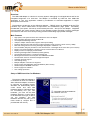
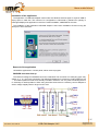
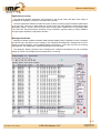
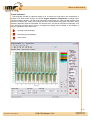
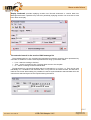
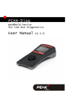
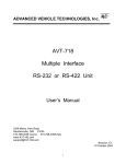
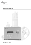
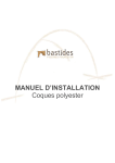
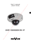
ideas make 6.7.2006
future
ideas make future
USB-CAN Adapter
TRIPLE drivers
V4.5
© IMFsoft, Ltd.
Document: 1001-0002-05
USB-CAN Adapter V4.5
/15
www.imfsoft.com
[email protected]
ideas make future
Overview
The USB-CAN adapter is a device for an easy dynamic debugging of CAN applications and for the
transparent diagnostic of a CAN bus. The adapter is controlled by USB bus from USB-CAN
application or your own application created by modification of CAN-Start application in Delphi
development environment.
The hardware construction of the USB-CAN adapter – TRIPLE drivers is established at the FTDI
FT245RL chip, Atmel T89C51CC01 microprocessor and PCA80C251 (High speed - ISO11898),
PCA80C252 (Low speed - ISO11519) and AU5790 (One wire - J2411) into one adapter. Integrated
microprocessor with cache memory reduce of the operating system load when receiving messages
from CAN bus and at the same time providing precision transmitting eight parallel messages.
Main Features
•
•
•
•
•
•
•
•
•
•
•
•
•
•
•
•
•
•
•
•
High speed, Low speed and One wire CAN drivers into one adapter
Fully compliant with CAN 2.0A and CAN 2.0B
15 Independent Message Centres
10kbps to 1Mbps Transfer Rate, support users speed setting
Dynamic data receiving and showing of CAN messages (using processor cache memory 256B)
Real and average time of receiving messages displayed in resolution 1ms
The immediate, delayed, periodical or auto transmission 8 messages at the same time (1ms to 65,5s)
Display of received messages - Number, Period, Load and Errors of CAN bus
Replay function for replaying recorded data
Receiving messages without ACK bit (Listening Mode)
The extended searching in a received message list
Messages transmission and reception from REMOTE FRAME
The automatic insert of received messages description
CANopen protocol support
User setting saving
Multiple adapters connection to single PC
Power supply and initialization LED signalization (Red / Green)
Standard layout CANNON connector
Power supply from USB bus
Over voltage protection
Setup of USB bus driver for Windows
The working USB-CAN adapter is
a conditional of driver for USB bus.
After USB-CAN adapter connection
to computer, the operating system
Windows will automatically detect
a new device and start Add
Hardware Wizard. If Windows does
not successfully find your new
hardware, you must use the Add
Hardware Wizard in Control Panel
to tell Windows what type of device
you are installing. The Add
Hardware Wizard may ask you to
insert media (a compact disc is
provided with the device).
1/15
Document: 1001-0002-05
USB-CAN Adapter V4.5
www.imfsoft.com
[email protected]
ideas make future
According to the Guide choose Install hardware that I manually select from a list (Advanced) and click
Next. In the next step choose Search plug in media such as disc or CD-ROM. Insert the installation
CD provided with the USB-CAN adapter in CD ROM unit and press Next.
In the following window you might see information about possible driver incompatibility with
windows system. In this case press Next or Continue again.
The setup will be now realized and the driver will be registered in the Windows system. If you look
into Control panel -> System -> Hardware -> Hardware administrator you will see the name of just
installed driver, FTDI FTU2XX Device, after clicking USB Bus controller.
Warning: USB-CAN adapter must be connected to the computer.
Removal
If you want to remove the adapter controller, uninstall USB-CAN adapter from the computer and
uninstall the controller in Control panel, Add or remove program named FTDI FTD2XX USB Drivers.
2/15
Document: 1001-0002-05
USB-CAN Adapter V4.5
www.imfsoft.com
[email protected]
ideas make future
Installation of the application
The application of USB-CAN adapter works under the Windows 95 and higher. It requires 4MB of
empty space in hard disc. The minimum PC configuration is influenced by demand for quantity of
massages displayed in application in real time. Pentium 233MHz, 32MB RAM is accurate.
The installation of the application USB-CAN adapter is done from installation CD and running file
Setup.exe. Then click Next.
Removal of the application
Uninstall the application in Control panel, Add or remove program.
CANNON connector bus up
The CAN bus busage for CANNON connector is standard. The connector is of male plug type. Only
outlets 2, 3, 5, 7 and 9 are connected. The USB-CAN adapter don’t contain any load impedance 120
Ω. This load impedance needs to be already included in CAN bus. For very short conducting there is
no necessity for load impedance. When using One Wire drivers then is necessary connect adapter to
extern voltage supplay Vbat in range from 6 to 24V.
3/15
Document: 1001-0002-05
USB-CAN Adapter V4.5
www.imfsoft.com
[email protected]
ideas make future
Application servicing
The USB-CAN adapter application was projected to be served easily and offers wide range of
possibilities in displaying, conversion and data saving as well.
The main application Windows contains a number of items for setting required CAN bus parameters
in the right part. This part is called CAN bus control board. The main Windows contains bookmarks
Messages, Signals, Trends a Records, where each of them offers a different form of processing data
from CAN bus. Except Messages bookmark every bookmarks requires setting of value database
through Signals database configuration windows.
Messages bookmark
Message bookmark enables immediate CAN message display with a possibility to insert a message
description about importance of the message. The immediate and diagnostic message list serves to
display received messages. The immediate display prints data in lines with a print out of receiving
message time, the identification, data and description of the message.
The diagnostic display represents the messages with a different Identification ID, the immediate
display of number of messages and an average time or receiving.
4/15
Document: 1001-0002-05
USB-CAN Adapter V4.5
www.imfsoft.com
[email protected]
ideas make future
Signals bookmark
This bookmark enables the conversion and CAN data display in format of real values transferred on
CAN line. The configuration is needed to be done before through the window Signals database
configuration or straight when choosing values to display. It is possible to display 144 discrete
values, 64 numeric or text values and 9 numeric values in a form of the analog meter.
Value choice
5/15
Document: 1001-0002-05
USB-CAN Adapter V4.5
www.imfsoft.com
[email protected]
ideas make future
Trends bookmark
This bookmark provides an objective display up to 15 values in the real trend. The configuration is
needed to be done before through the window Signals database configuration or straight when
choosing values to display. The real trend rises till the chosen time (e.g. 20s) and then rotates 1s till
the time of overflow (60 - 120s), when running are set to zero and their rising again. Whenever during
displaying depicture might be interrupted. The function Zoom can also be used when interrupting. The
print, the saving trend (in format *.bmp) or a background change can be realized on the desktop of
trend by right button of mouse as well.
Running the trend display
Disrupting the trend display
Value choice
6/15
Document: 1001-0002-05
USB-CAN Adapter V4.5
www.imfsoft.com
[email protected]
ideas make future
Records bookmark
This bookmark enables parallel saving of the received messages or values into a text file. The
configuration is needed to be done before through the window Signals database configuration or
straight when choosing parameters to display. It is possible to save up to 160 values in the same
time. The number of so written data is limited only by the size of the used hard disc of the computer.
The saved file with messages or values can be processed through MS Excel application.
Running the record to the file
Stop the active record
Value choice
7/15
Document: 1001-0002-05
USB-CAN Adapter V4.5
www.imfsoft.com
[email protected]
ideas make future
CANopen bookmark
This bookmark provides the tool for one device controlling via communication standard
CANopen CiA DS-301. It permit a few operation with object NMT, Node Guarding, Sync, Time
Stamp, Emergency, PDO a SDO. The object range of periodic message timing it may be choosen
from 10ms to 10s. The PDO object configuration is needed to be done before through the window
Signals database configuration or straight when choosing parameters to display. More
information in apendix.
Transmit data frame
Abort transmitting
PDO signals choice
Upload SDO
Download SDO
8/15
Document: 1001-0002-05
USB-CAN Adapter V4.5
www.imfsoft.com
[email protected]
ideas make future
Value database configuration
First the displayed values must be set in the window Signals database configuration, and then
they can be displayed in the real form. It is possible to set Name, Unit, Description, Identification CAN
ID, Data type, beginning position of saving data Position, Length of the saved data, Storage data
format, parameters for conversion Multiplier and Offset and format of displaying the defined number
of Decimal Places, Maximum and Minimum.
Data types which user might chose from: BYTE (8b), UBYTE (8b), INTEGER (16b), UINTEGER
(16b), LONG (32b), ULONG (32b), BOOL (1b), TEXT (8-64b). Those with Uxx characterize no
marked type.
Storage data format enable choice of two main formats:
0 >> 63 (Intel) – chooses data from received message from the lowest bit up to the highest bit.
63 >> 0 (Motorola) – chooses data from received message from the highest bit up to the lowest bit.
Lo-Hi – this format exchanges the order of individual Byte data Lo-Hi-Lo-Hi instead of Hi-Lo-Hi-Lo.
The input value database might be saved to the user’s file with the *.sf
9/15
Document: 1001-0002-05
USB-CAN Adapter V4.5
www.imfsoft.com
[email protected]
ideas make future
Attach, indication and USB CAN adapter activity conduct
The active adapter attach is signalized in upper bar of application through information Device
Present. This information signalizes he right activity of USB bus but not complete activity of USB
adapter. The confirmation replies signalize the processor activity of the adapter. These are the
reaction on individual commands sent to microprocessor. The replies of the adapter are displayed in
form of short texts in the bottom state bar on the right:
•
•
•
•
•
•
•
•
•
Adapter Ready
CAN Initialization
MC Initialization
OUT Initialization
Time Initialization
CAN Disable
MC Disable
OUT Disable
Pause
The communication with USB-CAN adapter is conducted through press buttons from the control
panel of the main application window and press buttons from the window for transmitting Can
messages. Every press button sends data sequence that realizes the adapter configuration. Only
Resetting message list button doesn’t transmit any message.
Adapter initialization
It makes required time and CAN bus register setting. The CAN bus register set up is
influenced by user’s choice. After changing CAN parameters in set up, the changes need
to be written in USB-CAN adapter through this press button. Or use automatic user’s set
up for automatic initialization
Abort adapter initialization
It cancels all CAN bus register set ups. It stops from both receiving and transmitting data.
Clear message list
It makes immediate resetting of the received message list. It doesn’t transmit any
message to the adapter.
Pause
It makes immediate stop receiving and transmitting data on CAN line. After the next click
the primary action refreshes. The activity refresh happens also when pressing Adapter
initialization button.
Message transmitting
It opens the setting message window for transmitting. The press button is not displayed in
Listening mode regime because in this regime it is not possible to transmit messages on
CAN line.
10/15
Document: 1001-0002-05
USB-CAN Adapter V4.5
www.imfsoft.com
[email protected]
ideas make future
CAN bus parameter set up
CAN setting – The transmitting speed optional in 10kbps to 1Mbps volume is a definite parameter for
CAN bus set up. The select of transmitting speed is realized in CAN setting panel, Bite Rate. If the
select is not accurate the reception nor required data display aren’t realized.
It possibility for users selection bit rate speed through window.
Bit rate registers configuration and Calculator function. Active
this window by click the symbol
CAN setting panel.
The important item is Listening Mode, which enables reception CAN messages without their
confirmations by non-active bit ACK. The sampling position choice and number of sampling point set
up don’t influence CAN message reception or transmitting
ID setting – The selection of received CAN identification is realized in ID setting panel, items Tag and
Mask. The set up is realized by defining the identification bit mask in format Hex. The Tag serves for
the basic set up. The Mask serves for validity specification of individual Tag bits.
Tag and mask set up for CAN 2.0A, e.g.:
Reception of all ID 000H -7FFH Reception of ID 100H
Tag 000 0000 0000B = 0H
Mask 000 0000 0000B = 0H
Reception of ID 100H-103H volume
Tag 001 0000 0000B = 100H Tag
Mask 111 1111 1111B = 7FFH Mask
001 0000 0000B = 100H
111 1111 1100B = 7F8H
The right CAN 2.0A or CAN 2.0B frame specification is needed for message reception and
transmitting on CAN bus. This selection is realized in ID setting panel, 2.0A (11bit) a 2.0B (29bit)
items.
CAN message transmitting
The window Transmit Frames serves transmitting the messages. It enables easy transmitting of own
messages on CAN line. Messages bookmark provides possible to transmit up to 8 messages at
the same time. The message is completely defined by the transmitting regime (once, periodic in data
or enquiry combination), by the time (delayed or period), by the identification and by data for
transmitting. To gain sequence information there is Show transmitting Frame function that enables
the reception and display of transmitted messages in the list of immediate and diagnostic message
display. The set messages can be saved in user’s file with an extension *.sf.
11/15
Document: 1001-0002-05
USB-CAN Adapter V4.5
www.imfsoft.com
[email protected]
ideas make future
The window Transmit Frames works in four regimes of message transmitting. The regimes are
subsequently switched by clicking vertical press buttons on the left. One press button attaches to just
one message to transmitting.
Data FRAME Once transmit – simple message transmitting Data FRAME with delay Time
[ms] set in 0 to 65535ms volume.
Data FRAME Periodic transmit – periodic message transmitting Data FRAME with period
Time [ms] in 1 to 65535ms volume.
Remote FRAME Once transmit – simple message transmitting Remote FRAME with delay
Time [ms] set in 0 to 65535ms volume.
Remote FRAME Periodic transmit – periodic message transmitting Remote FRAME with
period Time [ms] in 1 to 65535ms volume.
AUTO RESPONSE – automatic message transmitting after receive with delay Time [ms] set
in 0 to 65535ms volume.
The CAN identifications need to be set in the definite volume according to chosen specification
CAN 2.0A and CAN 2.0B in format HEX.
Also data need to be set in HEX format in volume 0 to 8 byte. It is possible to separate the set
bytes by a gap, comma or by another separating character. The number of set bytes is decisive for
transmitting Remote FRAME, not their content.
The press buttons Transmit Frame on the right make run the message transmitting.
Transmit Frame
It sends a set message to USB-CAN adapter. The adapter sends the message to CAN
line according to set parameters immediately, with delay or periodically.
Abort transmitting
It cancels periodical or delayed message transmitting.
Signals bookmark provides transmitting the own signals. The configuration is needed to be done
before through the window Signals database configuration or straight when choosing values to
transmitting. Simple or Periodic data transmitting are getting from actual signals value with identical
ID. The data transmitting are showing in Messages bookmark. You must on mouse click (Discrete) or
change position on the scroll bar (Numerical) for change signals state. The periode you can change
through the window Transmitting setting (double click on signals + key CTRL).
12/15
Document: 1001-0002-05
USB-CAN Adapter V4.5
www.imfsoft.com
[email protected]
ideas make future
Replay bookmark provides replaying records from Records bookmark or receive data from
Messages bookmark. It possible Loop check for periodicaly replaying records. You must click to Load
buton after record play.
The extended search in the received CAN message list
The extended search in the received CAN message list shortens searching time represented by
Find Data. It enables to combine several parameters for rising up the search effect.
•
•
•
Line – search according to list lines
Time – search according to time. The time doesn’t have to be complete
D – search according to CAN ID identification
The parameter line, type and ID enables search in intervals from, to or from – to. They can be used
individually or in combination with searched data, or only data can be searched data. The data set is
made in Hex format. When setting it is possible to insert XX symbol between searched data which will
cause that a searched byte won’t be important during the search.
13/15
Document: 1001-0002-05
USB-CAN Adapter V4.5
www.imfsoft.com
[email protected]
ideas make future
The automatic message description insert
The CAN bus enables transmitting of messages with various identifications. The high number of
sent identifications might cause a difficult orientation. The identification message description enables
easier work with the high number of identifications.
The Define ID Description window serves to create the identification description. The identification
description is realized in single lines of the table. The confirmation of description setting is realized by
pressing Next ID. The order of setting identification can be random. When pressing OK button they
will be sorted ascending.
Such a set description will be automatically displayed in immediate and diagnostic message list in
Description column with appropriate identification value displayed in ID[Hex] column.
The identification set can be also saved in user’s file with an extension *.sf.
14/15
Document: 1001-0002-05
USB-CAN Adapter V4.5
www.imfsoft.com
[email protected]
ideas make future
The user’s application CAN Start and CAN Start Dll
The CAN Start application provides you with creating user’s own application using USB-CAN
adapter. The application source code of CAN Start and CAN Start Dll application is written for Delphi
5 development environment and higher. This application is in Delphi 7.
The easy use enables procedures ReceiveCanData and TransmitCanData. In case of large
application changes study the commented application source code. With help of reports it is possible
to set an individual register configuration of the used CAN microprocessor.
ReceiveCanData (Hour, Minute, Second, Millisecond: integer; RTR: Boolean; ID, Count: Integer; Data:
array of Byte);
This procedure is automatically executed when receiving the Can report. It includes all
information needed for the report identification.
Hour, Minute, Second, Millisecond – the exact time of report reception [23:59:59:999]
RTR – the report type Data Frame (RTR=false)/Remote Frame (RTR=true)
ID – CAN identificator of a report
Count – the number of received data
Data – the array of received data
TransmitCanData (MCx, Per, Sys: Integer; RTR: Boolean; ID, Count: Integer; Data: array of Byte)
This procedure enables to enter a report to transmitting at CAN line. The reports can be
transmitted through various Message centres to which the counters of periodical or delayed
transmitting are assigned. It is possible to transmit 8 reports at the same time.
MCx – Message centre [0..7]
Per – the period of message transmitting/delaying [0..65525][ms]
Sys – the transmitting mode
1= one transmitting with delay = per [ms]
3= periodical transmitting with period = per [ms]
4= immediate transmitting independent on per parameter
+8= receiving and display of a transmitted message
RTR – the report type Data Frame (RTR=false)/Remote Frame (RTR=true)
ID – CAN identification of a report
Count – the number of received data
Data – the array of received data
News: http://imfsoft.com/hardware/produkty/usb-can-adapter-triple-drivers.asp
15/15
Document: 1001-0002-05
USB-CAN Adapter V4.5
www.imfsoft.com
[email protected]