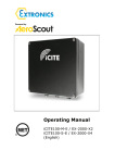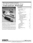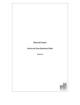
1
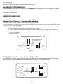
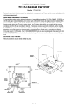
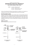
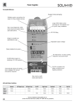
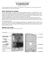
Installation and Operation Manual
STI REPEATER
Model: STI-34109
Thank you for purchasing this fine product. Your satisfaction is very important to us. Please read this manual
carefully to get the most from your new product.
HOW THE PRODUCT WORKS
STI offers wireless products designed to alert you of several different conditions. The STI REPEATER is a 433
MHz radio signal receiver and transmitter that effectively doubles the transmission range of STI sensors to STI
receivers. The REPEATER will filter out all radio signals that are not using 433 MHz STI protocol. When any STI
protocol signal packet (except STI 8-Channel Receiver) is received, it transmits the same signal packet. There is
no limit to the number of STI sensors that may be used with the STI REPEATER.
It should be understood that multiple REPEATERS should NOT be used within reception range of each other
because a REPEATER will simply retransmit any STI protocol signal packet (except 8-Channel Receiver). Two
REPEATERS within reception range of each other can retransmit signal packets back and forth a few times when
sensor packet is received.
If a dual REPEATER system or further extended range applications are needed, please purchase STI 8-Channel
Receivers (STI-34108). The receivers will retransmit alert and trouble notifications of the sensor signals, but not
the actual signals themselves. Therefore, REPEATER feedback will not occur. The receivers work with up to 8
different STI wireless sensors.
BEFORE YOU START
Refer to this drawing to become familiar with all the parts.
FEATURES
• Extends system range.
• Receives and retransmits distant STI protocol wireless device signals (except for STI 8-Channel Receivers
signals) to receivers.
• Sensor reprogramming not required.
• All STI protocol alarm, supervisory and trouble signals are repeated to receivers.
• REPEATERS have their own unique ID for supervisory, tamper alert and low battery signals that can be
monitored with receivers.
• Antennas increase range for both reception and transmission of signals.
• Backup battery protects during loss of external power (up to 72 hours).
SPECIFICATIONS
• External Supply: 9-18V AC or DC, 15 mA nominal (recommended 30+ mA rating).
• Three (3) 1.5V AAA Alkaline batteries: external power backup (up to 72 hours).
• Housing Dimensions: 4 x 6 3/8 x 1 ¼ in.
• Antenna length when inserted in housing: 7 ¾ in.
OPERATION
The REPEATER receives distant STI protocol sensor signals and repeats the information to
the receiver. Generally, STI sensors send 8 identical signal “packets” of information. The
REPEATER rejects any signal that is not an STI protocol packet and retransmits the complete
8 packet set to the receiver.
STI REPEATER’S wireless signals:
• Tamper Signal – tamper switch released when cover is opened or damaged
• Tamper Restore Signal – tamper condition corrected
• Low Battery Signal – battery charge low
• Low Battery Restore Signal – low battery condition corrected
• Supervisory Signal – sent every hour to monitor that REPEATER is within range
REPEATER and sensor enrolling:
• The receiver can monitor the REPEATER’S supervision and trouble signals when they are enrolled (if desired). • To manually send a REPEATER signal, press and release the tamper switch. Ensure the red LED blinks.
• To enroll sensors, follow the receiver’s programming instructions.
LEDS:
ONBLINKING
GREEN LED
AC/DC power on
Signal Received
RED LED
Low Battery Alert
(only with AC/DC power on)
Signal Transmitted
—2—
INSTALLATION GUIDE
The REPEATER is intended to be mounted indoors or in a waterproof environment. Review
the APPLICATIONS GUIDE for suggested setups.
1. Press the cover latch to remove top cover (do not lose tamper switch spring).
2. Remove the PCB from bottom cover.
Using the keyholes on the bottom cover as a template, mark the top and bottom mounting holes. Locate the
hole at least 1 foot away from the closest obstruction above.
3. Drill 3/16” holes.
4. Insert wall anchors, screws and washers (provided) and tighten to 1/8” gap.
5. TURN OFF POWER SUPPLY. Route power supply wires from the side (recommended) or hole from the back. a. Side installation – route wires through right wire guide and then left wire guide. Remove knockout on the
top cover.
b. Rear installation – run wires through back wire guide and then left wire guide.
6. Place bottom cover keyholes onto screws and orient device vertical. 7. Tighten screws.
8. On the PCB, insert the antennas into the outer antenna terminals marked “ANTENNA.” Tighten the antenna
terminal screws.
9. Snap PCB into bottom cover so the antennas are on the plastic stands.
10.Remove the battery tab. The red LED blinks when the batteries are installed. If LED does not blink, press
and release the tamper switch. If LED still does not blink, replace batteries.
11 .Insert 12 Volt AC or DC power supply leads into the terminals marked “AC/DC 12V.” The positive and
negative terminals have interchangeable polarity. They may be oriented either +/- or -/+. 12.Turn on the power supply. The green LED turns on. If the red LED is on, replace the 3 AAA Alkaline
batteries.
13.(If desired) Program the REPEATER and/or the sensors into the receiver (follow the receiver programming
instructions). The receiver can monitor the REPEATER’S supervision and trouble signals when enrolled. To manually send a REPEATER signal, press and release the tamper switch. The red LED blinks when
transmitting.
14.If the REPEATER or the sensors do not program properly, move the REPEATER mounting location closer to the
receiver.
15.Latch the top cover in place. Ensure the power supply wires are routed properly. IMPORTANT NOTICE:
Information and specifications are subject to change without notice.
This product has been tested and complies with the specifications for a Class B digital device, pursuant to Part
15 of the FCC Rules.
These limits are designed to provide reasonable protection against harmful interference in a residential
installation. This equipment generates, uses and can radiate radio frequency energy and, if not installed and
used according to the instructions, may cause harmful interference to radio communications. However, there
is no guarantee that interference will not occur in a particular installation. If this equipment does cause harmful
interference to radio or television reception, which is found by turning the equipment off and on, the user is
encouraged to try to correct the interference by one or more of the following measures: - Reorient or relocate the receiving antenna - Increase the separation between the equipment or devices - Connect the equipment to an outlet other than the receiver’s - Consult a dealer or an experienced radio/TV technician for assistance
Operation is subject to the following two conditions: (1) this device may not cause interference, and (2)
this device must accept any interference, including interference that may cause undesired operation of the
device. Changes or modifications not expressly approved by Safety Technology International, Inc. could void
your authority to operate this equipment. To reduce potential radio interference to other users, the antenna
type and its gain should be so chosen that the equivalent isotopically radiated power (e.i.r.p.) is not more than
that permitted for successful communication. This product meets the applicable Industry Canada technical
specifications. Le présent materiel est conforme aux specifications techniques applicables d’Industrie Canada.
FCC ID: U5X-RE324 IC: 8310A-RE324
—3—
WARNINGS
FOR INDOOR USE ONLY. Keep away from water or damp areas.
WARRANTY INFORMATION
Safety Technology International, Inc. warrants to the original consumer/purchaser that this product shall be free
of defects in material and workmanship under normal use and circumstances for a period of one (1) year from
the original date of purchase.
APPLICATIONS GUIDE
Circle = sensor
General Use (Figure 1) – sensors out of range
• For “out of range” sensor(s), position REPEATER between sensor and receiver.
• If some sensors are “in range” of the receiver, mount the REPEATER closer to the out of range sensor. The REPEATER should
not receive the “in range” sensor packets.
• If it is not possible for the REPEATER to receive “out of range” sensors without also picking up “in range” sensor packets:
• Move the receiver location forcing “in range” sensors “out of range.”
• Purchase an STI 8-Channel Receiver to mirror the “out of range” packets to the original 8-Channel Receiver.
• Continue to use the receiver as it is, allowing duplicate sensor packets to be received. This should not change the receiver operation.
• Reconfigure system.
Single Repeater System - General Use
Multiple Sensor/Re
Keep Repeater out of range
from non-repeater sensor
Out of range
sensor
Up to 1000 ft.
to farthest sensor
Up to
1000 ft.
Up to
1000 ft.
1 - MIRROR MASTER OFF/ON
2 - NORMAL/ENROLL
3 - AUTO RESTORE/LATCH
4 - SIREN TIME/MIRROR#
5 - SIREN TIME/MIRROR#
6 - CHIME OFF/ON
7 - NORMAL/DELETE
8 - MIRROR SLAVE OFF/ON
SW4
SW5
SIREN
TIME
MIRROR #
OFF
ON
OFF
ON
OFF
OFF
ON
ON
DISABLED
30 SEC
180 SEC
ON CONT
1
2
3
4
In range
sensor
Repe
Receiver
Repeater
Figure 1
Extended Range System
System with Distance be
Multiple Sensor/Receiver System (Figure 2)
The REPEATER will receive and transmit any STI protocol signal packets received (except 8-Channel
Receiver).
Up to
Up to
1000 ft. to
to packets through
Up to
Up to
Multiple sensors can be arranged to Up
pass
the REPEATER
to multiple receivers.
1000 ft.
farthest sensor
1000 ft.
1000 ft.
1 - MIRROR MASTER OFF/ON
2 - NORMAL/ENROLL
3 - AUTO RESTORE/LATCH
4 - SIREN TIME/MIRROR#
5 - SIREN TIME/MIRROR#
6 - CHIME OFF/ON
7 - NORMAL/DELETE
8 - MIRROR SLAVE OFF/ON
SW4
SW5
SIREN
TIME
MIRROR #
OFF
ON
OFF
ON
OFF
OFF
ON
ON
DISABLED
30 SEC
180 SEC
ON CONT
1
2
3
4
Receiver
(Master)
System - General Use
Keep Repeater out of range
from non-repeater sensor
1 - MIRROR MASTER OFF/ON
2 - NORMAL/ENROLL
3 - AUTO RESTORE/LATCH
4 - SIREN TIME/MIRROR#
5 - SIREN TIME/MIRROR#
6 - CHIME OFF/ON
7 - NORMAL/DELETE
8 - MIRROR SLAVE OFF/ON
1000 ft.
SW4
SW5
SIREN
TIME
MIRROR #
OFF
ON
OFF
ON
OFF
OFF
ON
ON
DISABLED
30 SEC
180 SEC
ON CONT
1
2
3
4
Receiver
(Mirrored)
Repeater
1 - MIRROR MASTER OFF/ON
2 - NORMAL/ENROLL
3 - AUTO RESTORE/LATCH
4 - SIREN TIME/MIRROR#
5 - SIREN TIME/MIRROR#
6 - CHIME OFF/ON
7 - NORMAL/DELETE
8 - MIRROR SLAVE OFF/ON
SW4
SW5
SIREN
TIME
MIRROR #
OFF
ON
OFF
ON
OFF
OFF
ON
ON
DISABLED
30 SEC
180 SEC
ON CONT
1
2
3
4
Receiver
RepeaterSensor/Receiver System
Multiple
System Range
(Up to 6000 ft. span - with a full mirrored system
Keep Repeater out
from each ot
Up to
8 sensors
1 - MIRROR MASTER OFF/ON
2 - NORMAL/ENROLL
3 - AUTO RESTORE/LATCH
4 - SIREN TIME/MIRROR#
5 - SIREN TIME/MIRROR#
6 - CHIME OFF/ON
7 - NORMAL/DELETE
8 - MIRROR SLAVE OFF/ON
SW4
SW5
SIREN
TIME
MIRROR #
OFF
ON
OFF
ON
OFF
OFF
ON
ON
DISABLED
30 SEC
180 SEC
ON CONT
1
2
3
4
Receiver #1
Up to
1000 ft.
Up to
1000 ft.
Up to 1000 ft.
to farthest sensor
1 - MIRROR MASTER OFF/ON
2 - NORMAL/ENROLL
3 - AUTO RESTORE/LATCH
4 - SIREN TIME/MIRROR#
5 - SIREN TIME/MIRROR#
6 - CHIME OFF/ON
7 - NORMAL/DELETE
8 - MIRROR SLAVE OFF/ON
SW4
SW5
SIREN
TIME
MIRROR #
OFF
ON
OFF
ON
OFF
OFF
ON
ON
DISABLED
30 SEC
180 SEC
ON CONT
1
2
3
4
In range
sensor
Repeater
Receiver
Range System
– Sensor
Up to
8 sensors
1 - MIRROR MASTER OFF/ON
2 - NORMAL/ENROLL
3 - AUTO RESTORE/LATCH
4 - SIREN TIME/MIRROR#
5 - SIREN TIME/MIRROR#
6 - CHIME OFF/ON
7 - NORMAL/DELETE
8 - MIRROR SLAVE OFF/ON
SW4
SW5
SIREN
TIME
MIRROR #
OFF
ON
OFF
ON
OFF
OFF
ON
ON
DISABLED
30 SEC
180 SEC
ON CONT
1
2
3
4
Receiver #2
System with Multiple Locations Monitored Centrally
Figure 2
Up to
1000 ft. to
farthest sensor
Keep out of range
System with Distance
2 Locations
— 4between
—
Up to
1000 ft.
Up to
1000 ft.
Up to
1000 ft. to
farthest sensor
Receiver
Repeater
Extended Range System (Figure 3)
The REPEATER may be used to extend the range of sensors to a multiple STI 8-Channel Receiver mirroring
system.
Extended Range System
Up to
1000 ft.
Up to
1000 ft.
Up to
1000 ft.
1 - MIRROR MASTER OFF/ON
2 - NORMAL/ENROLL
3 - AUTO RESTORE/LATCH
4 - SIREN TIME/MIRROR#
5 - SIREN TIME/MIRROR#
6 - CHIME OFF/ON
7 - NORMAL/DELETE
8 - MIRROR SLAVE OFF/ON
SW4
SW5
SIREN
TIME
MIRROR #
OFF
ON
OFF
ON
OFF
OFF
ON
ON
DISABLED
30 SEC
180 SEC
ON CONT
1
2
3
4
System with Distance
Up to
1000 ft. to
farthest sensor
1 - MIRROR MASTER OFF/ON
2 - NORMAL/ENROLL
3 - AUTO RESTORE/LATCH
4 - SIREN TIME/MIRROR#
5 - SIREN TIME/MIRROR#
6 - CHIME OFF/ON
7 - NORMAL/DELETE
8 - MIRROR SLAVE OFF/ON
Receiver
(Master)
SW4
SW5
SIREN
TIME
MIRROR #
OFF
ON
OFF
ON
OFF
OFF
ON
ON
DISABLED
30 SEC
180 SEC
ON CONT
1
2
3
4
Receiver
(Mirrored)
Up to
1000 ft.
Repeater
12345678-
Re
Repeater
Single Repeater System - General Use
Multiple Sensor/Receiver System
Keep Repeat
from e
System Range
(Up to 6000 ft. span - with a full mirrored system
Keep Repeater out of range
from non-repeater sensor
Figure 3
Up to
8 sensors
1 - MIRROR MASTER OFF/ON
2 - NORMAL/ENROLL
3 - AUTO RESTORE/LATCH
4 - SIREN TIME/MIRROR#
5 - SIREN TIME/MIRROR#
6 - CHIME OFF/ON
7 - NORMAL/DELETE
8 - MIRROR SLAVE OFF/ON
SW4
SW5
SIREN
TIME
MIRROR #
OFF
ON
OFF
ON
OFF
OFF
ON
ON
DISABLED
30 SEC
180 SEC
ON CONT
1
2
3
4
Receiver #1
System
- General
Use
Multiple
Sensor/Receiver
System
Central
Monitoring
of Multiple
Locations
(Figures
5)
Up4
to and
1000 –ft.Sensor
Up to
1000 ft.
to farthest sensor
Up to
8 sensors
Repeater
A receiver, or group of receivers,
Up to may be monitored in a central location between multiple REPEATERS as long as
1000 ft.
Up to
In range
the REPEATERS are out of range from each other.
8 sensors
Up to
Keep Repeater1000
out offt.range
Out
range
fromofnon-repeater
sensor
sensor
1 - MIRROR MASTER OFF/ON
2 - NORMAL/ENROLL
3 - AUTO RESTORE/LATCH
4 - SIREN TIME/MIRROR#
5 - SIREN TIME/MIRROR#
6 - CHIME OFF/ON
7 - NORMAL/DELETE
8 - MIRROR SLAVE OFF/ON
SW4
SW5
SIREN
TIME
MIRROR #
OFF
ON
OFF
ON
OFF
OFF
ON
ON
DISABLED
30 SEC
180 SEC
ON CONT
1
2
3
4
1 - MIRROR MASTER OFF/ON
2 - NORMAL/ENROLL
3 - AUTO RESTORE/LATCH
4 - SIREN TIME/MIRROR#
5 - SIREN TIME/MIRROR#
6 - CHIME OFF/ON
7 - NORMAL/DELETE
8 - MIRROR SLAVE OFF/ON
sensor
Receiver
SW4
SW5
SIREN
TIME
MIRROR #
OFF
ON
OFF
ON
OFF
OFF
ON
ON
DISABLED
30 SEC
180 SEC
ON CONT
1
2
3
4
1 - MIRROR MASTER OFF/ON
2 - NORMAL/ENROLL
3 - AUTO RESTORE/LATCH
4 - SIREN TIME/MIRROR#
5 - SIREN TIME/MIRROR#
6 - CHIME OFF/ON
7 - NORMAL/DELETE
8 - MIRROR SLAVE OFF/ON
Receiver #1
SW4
SW5
SIREN
TIME
MIRROR #
OFF
ON
OFF
ON
OFF
OFF
ON
ON
DISABLED
30 SEC
180 SEC
ON CONT
1
2
3
4
System
with Multiple Locations Monitored
Receiver #2 Centrally
UpSTI
to protocol packets received (except
Repeater – Because REPEATERS
Up towill
1000retransmit
ft.
• REPEATER Feedback
any
1000 ft.
to farthest sensor
Up to 8-Channel Receiver), if two REPEATERS are within reception range of each other they will send packets back
1000 ft.
Up toKeep out of range
In range
and forth to each
other. When using more than one REPEATER,
keep
them out 8ofsensors
range from each other. An Up to
Repeater
sensor
Up to
1000 ft. to
1000 ft. to
Receiver
STI 8-Channel
Receiver can be substituted for a REPEATER to farthest
eliminate
sensor this problem.
farthest sensor
Up
to
Up to
Receiver #2
Extended
Range– System
System
with
Distance
between
2 ft.
Locations
ft. the same
1000
• Dual REPEATER
Reception
If more than one REPEATER receives
a signal
packet1000
from
sensor, both
Repeater
Repeater
REPEATERS will retransmit the packet. This should not be an issue, but the programmed receiver will then
Keep out of range
Keep out of range
respond to both transmissions.
1 - MIRROR MASTER OFF/ON
2 - NORMAL/ENROLL
3 - AUTO RESTORE/LATCH
4 - SIREN TIME/MIRROR#
5 - SIREN TIME/MIRROR#
6 - CHIME OFF/ON
7 - NORMAL/DELETE
8 - MIRROR SLAVE OFF/ON
r
SW4
SW5
SIREN
TIME
MIRROR #
OFF
ON
OFF
ON
OFF
OFF
ON
ON
DISABLED
30 SEC
180 SEC
ON CONT
1
2
3
4
1 - MIRROR MASTER OFF/ON
2 - NORMAL/ENROLL
3 - AUTO RESTORE/LATCH
4 - SIREN TIME/MIRROR#
5 - SIREN TIME/MIRROR#
6 - CHIME OFF/ON
7 - NORMAL/DELETE
8 - MIRROR SLAVE OFF/ON
Up to
1000 ft.
1000 ft.
SW4
SW5
SIREN
TIME
MIRROR #
OFF
ON
OFF
ON
OFF
OFF
ON
ON
DISABLED
30 SEC
180 SEC
ON CONT
1
2
3
4
1 - MIRROR MASTER OFF/ON
2 - NORMAL/ENROLL
3 - AUTO RESTORE/LATCH
4 - SIREN TIME/MIRROR#
5 - SIREN TIME/MIRROR#
6 - CHIME OFF/ON
7 - NORMAL/DELETE
8 - MIRROR SLAVE OFF/ON
1000 ft.
SW5
SIREN
TIME
MIRROR #
OFF
OFF
ON
ON
DISABLED
30 SEC
180 SEC
ON CONT
1
2
3
4
Receiver
(Mirrored)
Up to
1000 ft. to
Up to
farthest sensor
System Range
1000 ft.
(Up to 6000 ft. span - with a full mirrored system
SW5
SIREN
TIME
MIRROR #
OFF
OFF
ON
ON
DISABLED
30 SEC
180 SEC
ON CONT
1
2
3
4
1
2
3
4
Repeater
Up to
1000 ft.
1 - MIRROR MASTER OFF/ON
2 - NORMAL/ENROLL
3 - AUTO RESTORE/LATCH
4 - SIREN TIME/MIRROR#
5 - SIREN TIME/MIRROR#
6 - CHIME OFF/ON
7 - NORMAL/DELETE
8 - MIRROR SLAVE OFF/ON
SW4
MIRROR #
DISABLED
30 SEC
180 SEC
ON CONT
sent to the receiver 2 times.
SW4
OFF
ON
OFF
ON
Receiver
(Master)
SW4
SW5
SIREN
TIME
MIRROR #
OFF
ON
OFF
ON
OFF
OFF
ON
ON
DISABLED
30 SEC
180 SEC
ON CONT
1
2
3
4
Receiver
(Mirrored)
1 - MIRROR MASTER OFF/ON
2 - NORMAL/ENROLL
3 - AUTO RESTORE/LATCH
4 - SIREN TIME/MIRROR#
5 - SIREN TIME/MIRROR#
6 - CHIME OFF/ON
7 - NORMAL/DELETE
8 - MIRROR SLAVE OFF/ON
SW4
SW5
SIREN
TIME
MIRROR #
OFF
ON
OFF
ON
OFF
OFF
ON
ON
DISABLED
30 SEC
180 SEC
ON CONT
1
2
3
4
SW5
SIREN
TIME
MIRROR #
SW4
SW5
SIREN
TIME
MIRROR #
OFF
OFF
ON
ON
DISABLED
30 SEC
180 SEC
ON CONT
1
2
3
4
OFF
ON
OFF
ON
OFF
OFF
ON
ON
DISABLED
30 SEC
180 SEC
ON CONT
1
2
3
4
SW4
SW5
SIREN
TIME
MIRROR #
OFF
ON
OFF
ON
OFF
OFF
ON
ON
DISABLED
30 SEC
180 SEC
ON CONT
1
2
3
4
Receiver
Repeater
Keep Repeater out of range
– Sensor
from each other
tem Range
- with a full mirrored system
Figure 4
– Sensor
System with Multiple Locations Monitored Centrally
Keep out of range
Up to
1000 ft. to
farthest sensor
Up to
System with Multiple Locations Monitored Centrally
Up to
1000 ft.
1000 ft.
Up to
1000 ft. to
farthest sensor
Repeater
Repeater
Keep out of range
Keep out of range
If 2 repeaters receive a
Up to signal from the
Upsame
to
1000 ft. sensor, the signal
1000will
ft. be
sent to the receiver 2 times.
Repeater
Keep out of range
If 2 repeaters receive a
signal from the same
sensor, the signal will be
sent to the receiver 2 times.
Up to
1000 ft. to
farthest sensor
SW4
SW5
SIREN
TIME
MIRROR #
OFF
ON
OFF
ON
OFF
OFF
ON
ON
DISABLED
30 SEC
180 SEC
ON CONT
1
2
3
4
Receiver
Keep out of range
SW4
SW5
SIREN
TIME
MIRROR #
OFF
ON
OFF
ON
OFF
OFF
ON
ON
DISABLED
30 SEC
180 SEC
ON CONT
1
2
3
4
1 - MIRROR MASTER OFF/ON
2 - NORMAL/ENROLL
3 - AUTO RESTORE/LATCH
4 - SIREN TIME/MIRROR#
5 - SIREN TIME/MIRROR#
6 - CHIME OFF/ON
7 - NORMAL/DELETE
8 - MIRROR SLAVE OFF/ON
SW4
SW5
SIREN
TIME
MIRROR #
OFF
ON
OFF
ON
OFF
OFF
ON
ON
DISABLED
30 SEC
180 SEC
ON CONT
1
2
3
4
Receiver
Keep out of range
1 - MIRROR MASTER OFF/ON
2 - NORMAL/ENROLL
3 - AUTO RESTORE/LATCH
4 - SIREN TIME/MIRROR#
5 - SIREN TIME/MIRROR#
6 - CHIME OFF/ON
7 - NORMAL/DELETE
8 - MIRROR SLAVE OFF/ON
Up to
1000 ft. to
farthest sensor
Up to
1000 ft.
1 - MIRROR MASTER OFF/ON
2 - NORMAL/ENROLL
3 - AUTO RESTORE/LATCH
4 - SIREN TIME/MIRROR#
5 - SIREN TIME/MIRROR#
6 - CHIME OFF/ON
7 - NORMAL/DELETE
8 - MIRROR SLAVE OFF/ON
SW4
SW5
SIREN
TIME
MIRROR #
OFF
ON
OFF
ON
OFF
OFF
ON
ON
DISABLED
30 SEC
180 SEC
ON CONT
1
2
3
4
Receiver
Up to
1000 ft.
Repeater
1 - MIRROR MASTER OFF/ON
2 - NORMAL/ENROLL
3 - AUTO RESTORE/LATCH
4 - SIREN TIME/MIRROR#
5 - SIREN TIME/MIRROR#
6 - CHIME OFF/ON
7 - NORMAL/DELETE
8 - MIRROR SLAVE OFF/ON
Up to
1000 ft. to
farthest sensor
Repeater
1 - MIRROR MASTER OFF/ON
2 - NORMAL/ENROLL
3 - AUTO RESTORE/LATCH
4 - SIREN TIME/MIRROR#
5 - SIREN TIME/MIRROR#
6 - CHIME OFF/ON
7 - NORMAL/DELETE
8 - MIRROR SLAVE OFF/ON
Up to
1000 ft. to
farthest sensor
SW4
SW5
SIREN
TIME
MIRROR #
OFF
ON
OFF
ON
OFF
OFF
ON
ON
DISABLED
30 SEC
180 SEC
ON CONT
1
2
3
4
Receiver
Up to
1000 ft.
Keep out of range
Up to
1000 ft.
Keep out of range
Repeater
Up to
1000 ft. to
farthest sensor
Figure 5
Repeater
1 - MIRROR MASTER OFF/ON
2 - NORMAL/ENROLL
3 - AUTO RESTORE/LATCH
4 - SIREN TIME/MIRROR#
5 - SIREN TIME/MIRROR#
6 - CHIME OFF/ON
7 - NORMAL/DELETE
8 - MIRROR SLAVE OFF/ON
Up to
1000 ft.
Receiver
Receiver
SW4
OFF
ON
OFF
ON
Repeater
Receiver
Repeater
1 - MIRROR MASTER OFF/ON
2 - NORMAL/ENROLL
3 - AUTO RESTORE/LATCH
4 - SIREN TIME/MIRROR#
5 - SIREN TIME/MIRROR#
6 - CHIME OFF/ON
7 - NORMAL/DELETE
8 - MIRROR SLAVE OFF/ON
1 - MIRROR MASTER OFF/ON
2 - NORMAL/ENROLL
3 - AUTO RESTORE/LATCH
4 - SIREN TIME/MIRROR#
5 - SIREN TIME/MIRROR#
6 - CHIME OFF/ON
7 - NORMAL/DELETE
8 - MIRROR SLAVE OFF/ON
—5 —
Up to
1000 ft. to
farthest sensor
Repeater
Up to
1000 ft. to
farthest sensor
Repeater
Up to
Up to
Up to
1000 ft. to Up to
1000 ft.
sensor
Up farthest
to
1000 Keep
ft. to Repeater
out of range1000 ft.
1000 ft.
farthest sensor
from each
other
Keep out of range
Repeater
OFF
ON
OFF
ON
SIREN
TIME
OFF
OFF
ON
ON
signal from
theft.
Up to
1000
toLocations
System
2same
sensor, the signal
will be
Up to with Distance between
1000 ft.
farthest sensor
1 - MIRROR MASTER OFF/ON
2 - NORMAL/ENROLL
3 - AUTO RESTORE/LATCH
4 - SIREN TIME/MIRROR#
5 - SIREN TIME/MIRROR#
6 - CHIME OFF/ON
7 - NORMAL/DELETE
8 - MIRROR SLAVE OFF/ON
Receiver
(Master)
1 - MIRROR MASTER OFF/ON
2 - NORMAL/ENROLL
3 - AUTO RESTORE/LATCH
4 - SIREN TIME/MIRROR#
5 - SIREN TIME/MIRROR#
6 - CHIME OFF/ON
7 - NORMAL/DELETE
8 - MIRROR SLAVE OFF/ON
SW5
If 2 repeaters
a
Upreceive
to
Range System
Up to
p to
0 ft.
SW4
OFF
ON
OFF
ON
Up to
1000 ft. to
farthest senso
Repeater
ADDITIONAL WIRELESS ALERT SERIES PRODUCTS:
STI-34099
STI-34104
STI-V34104
STI-34108 STI-34188
STI-34101
STI-34151
STI-34201
STI-34301
STI-34401
STI-34501
STI-34601
STI-34701
STI-34751
Single Channel Slave Receiver
4-Channel Receiver
4-Channel Voice Receiver
8-Channel Receiver
8-Zone Relay Board
Solar Powered Driveway Monitor Sensor
Battery Powered Driveway Monitor Sensor
Wireless Mailbox Alert Sensor
Wireless Garage Sentry Sensor
Wireless Universal Alert Sensor
Wireless Pool Alert Sensor
Wireless Doorbell Button
Indoor Wireless PIR
Outdoor Wireless PIR
STI-6200WIR
STI-6200WIR4
STI-6400WIR
STI-6400WIR4
STI-6517A
STI-6517B STI-30104
STI-30105
STI-34105
STI-34106
STI-34109
Wireless Fire Extinguisher Theft Stopper
Wireless Fire Extinguisher Theft Stopper w/Receiver
Wireless Exit Stopper Door Alarm
Wireless Exit Stopper Door Alarm with Receiver
Stopper Station Shield with Sound
Stopper Station Shield with Sound and Transmitter
Lamp Controller
Extended Antenna
Voltamax 12VDC (500mA) Power Supply
Keyfob
Repeater
2306 Airport Rd • Waterford, MI 48327
Phone: 248-673-9898 • Fax: 248-673-1246
[email protected] • www.sti-usa.com
Safety Technology International (Europe) Ltd.
Unit 49G Pipers Road • Park Farm Industrial Estate • Redditch
Worcestershire • B98 0HU • England • Tel: 44 (0) 1527 520 999
Fax: 44 (0) 1527 501 999 • Freephone: 0800 085 1678 (UK only)
E-mail: [email protected] • Web: www.sti-europe.com
We Protect the Things that Protect You.
Inst. Sht. STI-34109 DEC2012