1
RoboSail User Guide
Rev. 3
David Gaynor, Trevor Hooton, Eric Schneider, Brittany Strachota, Adela Wee
Advised by Andrew Bennett and Bradley Powers
April 26, 2013
Abstract
This document aims to provide basic instructions and recommendations sufficient to guide a high school team through the process of
making a robotic sailboat for the RoboSail competition sponsored by
US Sailing. Basic hardware and software setup instructions, as well
as troubleshooting and competition advice are included. Provided
software and further instructions are designed to provide basic functionality; students can pursue further enhancements to improve their
boat’s capabilities or performance.
1
1.1
Introduction
Executive Summary
Over the past two decades, high school students have been inspired and encouraged to pursue further education or careers in science and technology
through competitions like the FIRST Robotics Competition (FRC), FIRST
Tech Challenge (FTC), and SeaPerch. Although many of these participants
go on to pursue careers in technical fields, a recent study by the National
Science Foundation (NSF) showed that the United States produced only 10%
of the 5 million engineers who graduated in 2008 [7].
We have developed a robotic platform for use in RoboSail, a high school
autonomous sailing competition sponsored by US Sailing, designed to take
1
advantage of dropping hardware costs and increasing focus on encouraging
our youth to pursue a career in STEM (science, technology, engineering, and
math) fields. This platform is meant to serve as a low-cost “kit” that will allow students to develop a unique solution to the challenge of the competition
with appropriate scaffolding to ensure some measure of success regardless of
a team’s access to additional resources. The platform includes a one-meter
model sailboat, sensors and other hardware critical to the boat’s autonomous
operation, and a library of back-end software that students can use to bench
test sensors and quickly develop their own code.
1.2
Problem Space and Mission
This low-cost robotic sailboat platform provides students an opportunity to
develop technical and life skills as well as synthesize and apply facets of their
knowledge base. We hope the project will allow students to foster an interest
in technical fields, build valuable relationships, practice practical skills (public speaking, teamwork, professionalism, problem solving), and tie together
aspects of business (fundraising, budgeting, marketing) with applied math
and science.
The SailBot collegiate autonomous sailboat competition, sponsored by
US Sailing, was first held in 2006, and has grown every year since [10]. The
program is at a point in its lifecycle that is conducive to expansion into the
secondary school market.
Successful high school robotics have drawn over 45,000 high school students into the arena of robotic competition, bringing professionals and college
students along in mentor and volunteer roles. VEX and FIRST are household
names – a major criterion for success in this market. Tactics such as competitive gameplay, restricted resources, and opportunities for business and
marketing thinking contribute to the popularity of these programs. A strong
mentorship model pervades the competitions at all levels and leads to ultimate sustainability and a sense of ownership and pride in the participants, so
we encourage teams to seek committed mentors early in their establishment.
The following delineates the set-up processes for a basic robotic sailboat
to participate in this competition.
2
2
Computing
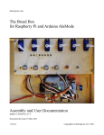
Different computing tasks have different requirements. Two main restrictions on the computational hardware for a robotic sailboat are size and input/output (I/O). The AlaMode [2] is designed to interface with the Raspberry Pi [9] in a complementary manner. The Pi handles input commands
over Wifi very nicely and the AlaMode has plentiful digital and analog I/O.
We have based our platform on the combination of Raspberry Pi and AlaMode because of the solid, flexible capabilities of these devices and their low
cost (at the time of this writing, approximately $40 for the Raspberry Pi and
$50 for the AlaMode).
2.1
Raspberry Pi
The Raspberry Pi is a small computer well-suited for ”hacker” projects. It is
booted from an SD card containing a Linux operating system image customtailored for the robotic sailboat. The SD card must be formatted, flashed,
and written by an external device. The file for the boat’s Raspberry Pi is
provided electronically, so students can flash an SD card following the included instructions.
The Pi behaves like a regular computer. One can plug in a monitor,
keyboard, mouse, and ethernet cable and treat it as a desktop, or install it
in a boat and communicate over wifi by opening an SSH (Secure SHell) to
communicate between two devices on the same network. Accessories that
use 3.3V logic and a USB cable that allow the user to directly plug into the
Raspberry Pi from a computer – eliminating the need for a spare keyboard,
mouse, or monitor setup – are available. (On a side note, that cable will only
allow you to communicate to the pi via command line and will not give you
access to the GUI.)
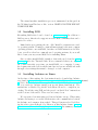
On the water, the ”thinking” takes place on the Pi. It receives inputs
down from the user (high-level commands such as waypoints and general behaviors) and up from the AlaMode (low-level sensor data). The ”think” code
on the Pi interprets all of this information, decides how to navigate through
the world, and sends commands to steer the boat down to the AlaMode,
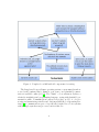
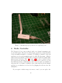
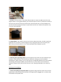
which controls the sail and rudder. See Figure 1 for the data flow.
3
Figure 1: Completed roadkill with all components for testing.
The Raspberry Pi uses a Linux operating system, so users must learn how
to use bash (command line). Linux is open source, and plentiful documentation is available online (see [5]). The ”think” code is written in Python, a
relatively straightforward programming language, again with plentiful documentation online. Communication between devices and ”nodes” of code (for
storing and transferring variables and data) uses ROS (Robot Operating System) [8], a communications protocol specifically designed for robotic systems
with multiple asynchronous processes, such as this one.
4
2.2
Arduino
The Arduino microcontroller is widely accepted as one of the easiest ways to
bridge the gap between computers and the real world. Wyolum, an international group of hardware tinkerers, decided to take this open source hardware
and reconfigure it for the Raspberry Pi. The Arduino device is aptly named
the AlaMode, as it is designed to sit atop the Raspberry Pi.
The AlaMode has six analog inputs and fourteen digital inputs/outputs,
which is sufficient for a robotic sailboat with three or four sensors and a
pair of servo motors. There is a wealth of support for and information on the
Arduino Uno on arduino.cc and the AlaMode on Wyolum’s website (see [13]).
Arduino code is written in C or C++ and data communication to and
from the Pi uses ROS. However, for the purposes of this project, all of this
basic code is provided. You can treat the AlaMode as a black box. Plug all
the sensors in and run code in Python; don’t worry about the nuts and bolts
in between unless you have a special interest in the inner workings.
ADD SPECIFICS ON HOW IT IS USED FOR THIS BOAT.
3
Beginning Steps for Students
Here are a few short tutorials to get you and your team up and running!
3.1
Installing Linux
The Raspberry Pi runs Linux, so it is much easier to develop code in a Linux
environment than through a PC running Windows or Mac. An advantage
is that most pre-written snippets of code you will want and need will be far
easier to download in a Linux system than in Windows. Skip this step if you
do not want to install Linux.
One of the easiest ways to begin running Linux is with a virtual machine. You can find details and instructions for doing that with Linux here:
<http://www.psychocats.net/ubuntu/virtualbox>.
Install the latest version available.
5
The virtual machine installation process is summarized in this guide in
the ’Working from Windows or Mac’ section. DREW SAYS THIS DID NOT
WORK FOR HIM.
3.2
Installing ROS
Everything ROS-related can be found on <www.ros.org>. In addition to
ROS resources, this site also supports an active ROS community that can be
queried for advice.
Immediately upon visiting the site, click ’Install’ for instructions sorted
by operating system. Ubuntu (a common Linux system) is the most common
operating system to use with ROS, but there are ROS instructions for Windows, as well as other less commonly used operating systems, if you would
like to learn your way around ROS before installing Linux.
Once you have installed ROS, a number of tutorials can be found at <www.
ros.org> under the ’Tutorials’ link. It is recommended that you complete
all of these tutorials every time you install ROS on a computer, because
the beginner tutorials both teach the introductory lessons on ROS and walk
through a few settings that must be changed on each computer.
3.3
Installing Arduino on Linux
At the time of this writing, the best instructions for downloading Arduino
were found at <http://blog.markloiseau.com/2012/05/install-arduino-ubuntu/
>. Notice that these instructions are for Ubuntu 12.04. If they do not work
for you, search for ’Arduino install [your specific Linux distribution]’. The
instructions on Mark’s blog should work when followed to completion, including ”Troubleshooting USB and the grayed out Serial Port” instructions
at the bottom of the article. These were necessary for us.
We experienced an interesting problem in Arduino set-up. When using
Arduino and trying to access the serial monitor, the communication between
the Arduino and computer often crashed. This problem was solved by following the advice given in Reply 3 by Pheaver on this Arduino forum: <http:
//arduino.cc/forum/index.php?topic=126292.0>. In summary, there is
6
sometimes an incorrect setting in an internal Arduino file when Arduino is installed on a Linux system. The serial monitor allows users to see communication between the Arduino and computer. An example use of the serial monitor: <http://learn.adafruit.com/adafruit-arduino-lesson-5-the-serial-monitor/
overview>.
3.4
AlaMode Setup
The user manual for the AlaMode can be found here: <https://docs.
google.com/document/d/1HBvd3KNmcs632ZgO6t_u37B-qwV6P9o9FQe62lGkumM/
edit>. This contains useful information about how to set up your AlaMode
(there is a little soldering involved), how to power your AlaMode, and more.
3.4.1
Installing Arduino and Proper Settings
HOPEFULLY NOT NECESSARY - OUR RASPBERRY PI IMAGE SHOULD
HAVE THIS ON IT
This guide provides useful instructions for installing Arduino with the
proper settings (AlaMode Getting Started): <http://wyolum.com/projects/
alamode/alamode-getting-started/>
3.4.2
Running Arduino on Raspberry Pi
When you have Arduino code written on the Raspberry Pi, you can run it
one of several ways.
First, if you set up the Raspberry Pi with a screen, mouse, and keyboard
you can run Arduino code relatively easily. Once you log in to the Raspberry
Pi and type ’startx’ to begin the desktop mode, simply start the Arduino IDE,
change the device to AlaMode, change the Serial Port to /dev/ttyS0, and
run your code. Instructions and pictures can be found on page 8 of <https://
docs.google.com/document/d/1HBvd3KNmcs632ZgO6t_u37B-qwV6P9o9FQe62lGkumM/
edit>.
If you are trying to run Arduino code from the Pi-AlaMode combination
without a monitor of some sort, you need to follow the instructions in the
next section. The code package we provide should do this for you at a basic
level; venture into these areas if you wish to customize your computer.
7
3.4.3
Arduino from Command Line
The command line in Linux allows users to type commands that the computer will run. When you connect to your Raspberry Pi over WiFi, you
will not be able to see the screen immediately. Instead, you will be able to
type commands that the Raspberry Pi then executes. Read more about the
command line at <http://linuxcommand.org/>.
You can run Arduino code on the Pi-AlaMode combination command line
by using tools found at <http://inotool.org/>. The easiest way to install
the tools is using ’pip install ino’ and following any other instructions on
the inotool website. After installation of ino, you can use the ’Quick Start
Tutorial’ on their website to practice using ino. A good way to test ino is to
first try it on your computer (if Arduino is installed) in conjunction with an
Arduino with which to test the sensors.
3.4.4
Working from Windows or Mac
If you are unable to install Linux directly on your machine...
Windows
If you are running Windows, you can run a virtual machine by doing the
following:
• Download the code examples for the Arduino and debug .ino files on a
Windows machine.
• Follow the instructions in this document for installing Arduino on your
computer (download Arduino, plug the Arduino into your computer,
point your computer toward the Arduino driver, run blink).
• Note that to power the servos, you will probably need to feed 9V
through the barrel connector in order to claim 5V (feeding 5V will
provide a voltage of approximately 4.7V, which might not be enough
to drive a servo).
Mac HEY GUYS, HOW DOES THIS WORK FOR MAC?
8
4
Setting Up Sensors
A successful robotic sailboat must gather and process information about
its surroundings. Specifically, the boat must be able to sense its absolute
location, its heading, and the direction of the wind. To gather these data,
our boat, Mr. Robateau, uses a GPS, compass, and wind vane. Sensor
recommendations can be found in Appendix A.
If you have already acquired all the reccomended sensors, and want to
get started right away, go straight to our Quick Start Guide, in Appendix
C. Otherwise, for descriptions of each sensor and tips for testing, continue
reading.
4.1
Sensor Testing
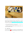
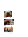
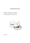
We recommend assembling a ’roadkill’ that includes all hardware laid out
on a board for testing. Affix the components to a rigid, nonconductive (i.e.
R
R
Sintra
, Lexan
, acryclic) board with tape, laid out and labeled for clarity
(see Figure 2).
REPLACE WITH PHOTO OF NEW ROADKILL
REPLACE WITH PHOTO OF NEW ROADKILL
4.2
GPS
The recommended GPS (see Appendix A) is fairly accurate (2-5m) and requires a battery to run. The GPS has a database of satellite/location information that it runs through when first booted up, also known as a cold
start, and uses the battery to store its last recorded location so that it will
be usable sooner. An Arduino tutorial for GPS is here: <http://learn.
adafruit.com/adafruit-ultimate-gps/direct-computer-wiring>.
AS SOON AS WE GET OUR CODE BASE ORGANIZED WE SHOULD
REPLACE THIS WITH OUR OWN CODE ALREADY LOADED ON THE
PI. INSERT PICTURE OF OUR FINAL GPS WIRING SETUP AND HOW
TO SOLDER TO THIS.
4.3
Compass
The recommended compass chip (see Appendix A) is a triple axis magnetic
sensor with a triple axis accelerometer for tilt compensation – very useful on
9
Figure 2: Mr. Robateau’s completed roadkill with all components for testing.
a boat rocking in the waves, propelled by a force that pushes it over! The
math used to process all this data is fairly complicated, but a code library
written by GitHub user ryantm converts the raw output of the compass to
a heading from 0◦ to 360◦ (see <https://github.com/ryantm/LSM303DLH>).
Use the most current files in this library to calibrate the compass.
The compass must be calibrated so that it reads the correct values. Follow the steps in the callibration section of this guide.
INSERT PICTURE OF OUR FINAL COMPASS WIRING SETUP AND
HOW TO SOLDER TO THIS.
4.4
Wind Vane
The wind vane is a homemade device based on an absolute magnetic shaft
encoder (see Appendix A) that uses a Hall Effect sensor with a full 360◦ range.
The encoder we used on Mr. Robateau is extremely low friction, as it spins
10
using a bearing. The encoder is recommended over a potentiometer because
most potentiometers do not have a true 360◦ range – they are usually about
40◦ shy. Further, most potentiometers wear out over time because their contacts are constantly rubbing against one another, unlike a magnetic encoder,
which uses no contact at all.
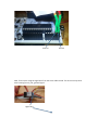
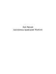
The encoder is wired as shown in Figure 3. The connector used is called
a micro jst plug specific to JR servos. You can also buy a pre-wired 4- or 6-ft
length of cable with this connector from US Digital, but we found it more
convenient to purchase multiple connectors and use spare PWM wire.
Note that these are all guidelines for you to get up and running! Feel free
to experiment with different shafts, fin sizes, materials, et cetera.
You will need to make a ’fin’ with enough surface area to move the encoder as the wind goes by. Cut a small fin shape from a rigid, lightweight
material, such as styrene foam used for making model airplanes or cardstock
wrapped with duct tape. Attach this to a small (about 4”) length of wire
with a small amount of durable tape. We used 1/32” carbon rod on Mr.
Robateau, but an unbent paperclip would also suffice.
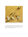
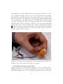
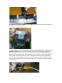
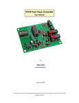
Poke a small hole through a coffee stirrer/tube-shaped material that fits
over the end of the encoder shaft and push the wind vane through it. We
used 1/8” diameter aluminum tube and placed shrink tubing over the hole
to hold the vane snugly (see Figure 4).
The encoder should be mounted carefully near the top of the mast such
that it does not interfere with the sails’ motion and can catch a true sample
of wind.
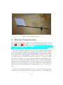
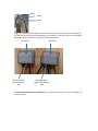
We used a wire saddle to mount the encoder in its waterproof case (see
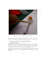
the ’Waterproofing’ section of this guide). Mark a mounting hole after positioning the saddle on the wide plastic portion of the mast (see Figure 5).
Drill a hole in the center of the marking to accommodate mounting hardware and attach the wire saddle to the mast (see Figure 6).
The waterproofed encoder fits into this mounted wire saddle.
11
Figure 3: Encoder wiring.
Note that the encoder has a full 360◦ range, but it is impossible to discern
the beginning and end of it from the outside. It is likely that the encoder
will not be installed straight. However, any offset error can be accounted for
in software. On startup, simply set the vane pointing in the direction you
wish 0◦ to be and run the calibration script.
12
Figure 4: Wind vane assembled.
5
Wireless Communication
We recommend the Edimax wifi dongle (with high gain antenna) shown in
Table 1 on page 29. It is simple to connect to wifi through the Pi. A great
tutorial can be found on Adafruit’s website: <http://learn.adafruit.com/
adafruits-raspberry-pi-lesson-3-network-setup/overview>.
In order to emulate competition protocol, the following router and wifi
range extender is recommended (as a similar setup will be used at competition): Asus RT-N66U Dual-band Wireless-N900 and Amped Wireless High
Power Omni-Directional 12dBi WiFi Antenna. This allows us to accomodate
boats that require b/g/n WiFi and teams are able to choose the type of WiFi
they will use on their boat. We recommend testing the range while on the
water before selecting a bandwidth. In general, we have found that n has the
lowest range but the highest capacity to carry data, and b has a farther range
than n but the lowest capacity to carry data. Without the range extender,
wifi with the high gain Edimax has a maximum range of about 500-700 ft on
land.
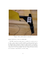
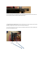
Maintain the wifi antenna mounted to the boat in a vertical position. The
antenna broadcasts orthogonal to the direction it points, so if the antenna is
13
Figure 5: The silver marking was made after positioning the wire saddle on
the wide plastic portion of the mast.
horizontal, it will not broadcast a signal toward your computer (see Figure 7).
This is especially important to consider when waterproofing the dongle.
We recommend coating all connections in a long-cure epoxy, specifically West
Marine’s ”West Systems” 105 Epoxy Resin and 205/206 Hardeners (206 is
slower and is a bit easier to deal with). Be sure to coat all joints and points of
connection sufficiently (see Figure 8). Note that non-5 minute epoxies have
a stage in the curing process in which they are flexible and can be easily
14
Figure 6: Wire saddle mounted to the mast.
trimmed with the use of an x-acto/utility knife.
The WiFi dongle has a moving joint; be careful not to get any epoxy on
it. Also be sure it cannot be twisted off (that is another area that is prone
to leaks) and if properly cured, if you try to twist it off, the lower joint of
the antenna will pop off instead. This is actually desirable, as it will allow
you to silicone the inside (because if water got in there as well, it would wick
down into the board and potentially destroy the dongle). The silicone allows
for the antenna to remain flexible even after curing.
15
Figure 7: Antenna in proper position before applying epoxy.
6
Radio Controller
The Vela model boat comes packaged with a two-channel transmitter and
receiver RC remote. However, for autonomous operations you may find that
it has an insufficient number of channels. We highly recommend each team
purchases a receiver and transmitter made by either JR, Spectrum, or Futaba
with at least four channels. Additionally, you may need the four-channel multiplexer from Pololu (see Table 1 on page 29) in order to switch between
teleoperation and autonomous control. If all channels are connected, you can
have full autonomous or full manual control. If you require one channel of
autonomy and one channel of manual control (autonomous sail and manual
rudder) you can function at a base level by plugging the sail servo into the
multiplexer.
If you require a farther range via remote control, you can replace the
16
Figure 8: Coating connections in epoxy. Be sure to coat all joints and points
of connection.
2.4Ghz hardware with a 900Mhz version.
Note that most boats only come with two servo channels – rudder and
sail. If you desire greater control over your boat, you may need to acquire a
receiver and transmitter with more than five channels.
7
7.1
Installing Hardware on the Boat
Waterproofing
Before putting anything out in the water, all of your equipment must be
splash proof (and relatively dunk-proof, too). Here are a few tutorials detailing Mr. Robateau’s waterproofing.
Waterproofing the Encoder
The encoder needs to be waterproofed and mounted to the mast. You can
17
use anything from a large-diameter straw to an empty lip balm tube to waterproof; just make sure the ends are sealed! You will probably need an empty
lip balm tube, petroleum jelly, silicone sealant, and maybe a popsicle stick.
First, cut off the bottom of the tube. Drill a hole just a little larger than the
encoder shaft in the cap. Fit the encoder in, making sure the mini jst plug
is in place. Fill the tube with petroleum jelly, reattach the ends, and apply
either hot glue or silicone sealant to both ends. Some excess petroleum jelly
will probably come out of the drilled hole for the encoder shaft (see Figure
9). Wipe this excess away from the shaft; a small amount will not hinder
mobility or performance. Drill two holes into the plastic on top of the mast,
and use a ziptie to hold it in place.
Figure 9: Top of encoder capsule with excess petroleum jelly coming out of
drilled hole for encoder shaft. Wipe this excess away.
Mounting the Encoder to the Mast
Things you will need: The completed waterproof encoder assembly and a
similarly sized holder for electrical cabling (like a cable clamp or saddle tie).
Attach the mount to the encoder assembly and mark the hole on the mast
18
Figure 10: Bottom of waterproofed encoder capsule.
through which you aim to mount it. Drill out this hole and fix it in place with
a nut and bolt. Run a cable tie through, or if it is the one piece, you are done.
INSERT MOUNTING ENCODER PICTURE HERE
Mounting the Brain
Things you will need: A locking, sealing plastic box (3.5 oz or so), silicone
sealant, velcro, hardware, 3/8” quick release pneumatic connectors, flexible
3/8” pneumatic hose, a small amount of Duct Seal (a.k.a. monkey dung),
5-pin Wago 222 connectors (to act as a power distribution block)
Alternatives to pneumatic connectors: bulkhead/IP 67 cables made by Adafruit
Highly recommended tools: Dremel with cutting disks, sanding drums, and
drill bits
19
One does not need to cut a hole in the boat to fit the box, but it is important to consider that the higher the center of mass, the more likely the
boat is to tip. We cut a hole in Mr. Robateau’s deck so we could situate the
electronics as low as possible, keeping the center of mass low.
For any boat, the relation of the center of mass to the center of buoyancy
is extremely important, and generally you want the distance between them
to be as great as possible. A low center of mass will be most stable.
Cutting a hole in the deck:
WARNING: Fiberglass is an irritant and can harm your lungs! Before cutting, ensure you have the proper safety gear, including a dust mask, safety
glasses, thick gloves, and a labcoat/long sleeved shirt or jacket. Make sure
your skin is protected/covered before sanding, grinding, or cutting into the
boat’s hull.
The Aquacraft Vela includes a support for one of the stays that may need
to be removed in order to cut a slot for the box. Proceed with caution,
watching for the piece of plywood that runs underneath the deck behind the
mast to distribute the load from the stay that was just removed. It is okay
to cut into some of it, but minimize the material removed.
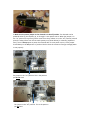
Place your container on the deck of the boat to determine and mark the
best placement (see Figure 11). Remove the container and carefully trace
the footprint of your box onto a sheet of paper. Cut it out with a precision
blade and check the fit of your box to that template. Repeat until you reach
the flanges of your box, then tape the template onto the deck of your ship
and cut it carefully. If you are concerned about cutting into something you
shouldn’t have, take a drill and drill a small hole through the deck first to
see if it is made of fiberglass and wood or just fiberglass at that point. To get
past the foam layer underneath, take a long utility knife or a carving knife
and cut away at the styrofoam. Proceed with caution and keep gloves on –
there is a sharp layer of fiberglass on top.
Mounting the rest of the electronics:
You should take the time to sketch out where you want your electronics to
go. Our plastic box was tall enough to mount the Raspberry Pi on the side
20
Figure 11: Place your container on the deck of your boat to find and mark
optimal placement.
wall instead of on the bottom of the box. Most of the electronics, if not
all, can be mounted with velcro. Try to minimize the number of exposed
contacts (use heat shrink if available) and make sure all holes in the box are
properly sealed. You will most likely want to mount the GPS facing upward.
Here are some detailed pictures of Mr. Robateau’s electronics setup.
PUT PICS OF BOX HERE.
8
Before Turning On The System Checklist
Here are some things you should make do before powering up your roadkill.
1. LABEL ALL WIRES!
2. Check wiring
• Power and 5V are plugged in to terminal blocks
• BEC (5V regulator) is plugged into terminal blocks
• Was BEC programmed to 5V (you can easily check this by using
a voltmeter to measure the output voltage)?
• Wires plugged into 5V are not also plugged into ground
3. Reduce risk of killing electronics
21
• Are all boards in cases/insulated in some way?
• Did you ground yourself/wear a grounding strap before handling
electrical components?
9
Calibration Guide
When your hardware is mounted on the boat and you have completed the
Quick Start manual found at the end of this document, ensuring your sensors are publishing data and your servos respond to your commands, you are
ready to calibrate your robotic sailboat.
The purpose of calibration is to align your sensor outputs to the real-world
phenomena they are measuring. For instance, it is practically impossible to
install the encoder such that the 0 value points straight ahead. It is quite
simple, however, to determine what the offset actually is and subtract it from
the measured value later.
To calibrate your hardware, follow this procedure:
• Start
– SSH in to the Pi and run calibrate.launch to begin the calibration
protocols
• Encoder
– Point the wind vane directly forward to set the 0 value
– The code will write this value to SensorOffsets.txt
• Servos
– Lay a protractor over the rudder with 90◦ pointing directly backwards
– Use the left and right arrow keys to turn the rudder to 45◦
– Press ’q’ to lock in the rudder servo’s minimum angle
– Repeat for 90◦ and 135◦
22
– Use the up and down arrow keys to let the sail all the way out to
90◦ from the boat
– press ’q’ to lock in the sail’s maximum angle
– Repeat for a sail angle of 0◦
– The code will write these values to SensorOffsets.txt
• Compass
– Rotate the compass all the way about each of its three axes
– The code will capture the xmin, xmax, ymin, ymax, zmin and
zmax values and write their values to SensorOffsets.txt
• GPS
– The GPS requires no calibration. It outputs latitude and longitude data out of the box. The conversion to UTM happens after
data is acquired.
• When data comes in from the sensors or is sent out to the servos, it
will be calibrated according to these values (check out sensors.py and
servos.py for the implementation)
• In a perfect world, you would only need to calibrate your boat once.
However, it is important to check that your sensors are publishing the
values you expect and recalibrate if necessary.
10
Testing Your Code
Whether you are writing you own code or simply testing your system with
the supplied Olinoboat code, you must be able to walk through each step of
the code and test it at each point. This both lets you know exactly what the
boat is doing at each point, and also lets you ensure that what the boat is
doing is correct.
Appendix D delineates a series of tests that will help you determine what
the code is trying to do. These tests assume that your roadkill is set up and
plugged into an Arduino, as you will see in the appendix. The Communications Testing guide also assumes knowledge from the Quick Start guide and
23
the ROS tutorials, so in going through the tests you may need to learn a few
new things.
You will run into strange, unforeseeable problems while testing, and will
need to find your way out of them. Looking to the internet for help is never
a bad idea as a first step. Best of luck!
11
Pre-sail Checklist
There are several ’checks’ and other measures that must be taken before
each time the boat is launched on the water including, but not limited to,
the following.
1. Check battery voltage
• voltage should be above 7.4V for a 2-cell LiPo or 11.1V for a 3-cell
LiPo
2. Check battery connector seals
• make sure you cannot see the terminals and that you cannot push
the connectors any closer
3. Ensure mast is secure
• post in depression
• ensure stays are tensioned properly, which in general means tightened evenly to the point where there is no slack in the stays but
they don’t ’hum’ when plucked
4. Latch all hatches securely
• position such that seals are properly aligned
• perform a light ’tug test’ on each latch
5. Check for any other water entry points; ensure they are sealed
• screw holes
• seals around electronics container
24
• seals around pneumatic connectors/bulkheads
6. Check the connectivity between devices
• follow directions in the connections testing manual
12
12.1
Competition
Things to Expect
Upon arriving at competition you should receive a packet of information
including instructions about general setup and logistical information (eg.
connecting wirelessly to the boat during competition, the debugging center
that will be available – either a laptop with a console cable or a full desktop
setup to plug the Raspberry Pi into), schedule for the competition, and
various other pertinent details.
12.2
Wireless Connectivity
Be creative when naming your team’s router (perhaps use your team name
in some way). The competition router will likely be named something like
’RoboSail’ or ’RoboSail20xx’, so avoid similarly general names.
12.3
Computers
A main computer will likely be provided at competition.
12.4
Prepare Cupcakes
For optimal performance at competition (for you and your boat), bring a
minimum of one dozen baked goods (ideally cupcakes) along. Bake with care.
Patriotic decoration is preferable. We understand that RoboSail judges tend
to appreciate sweets.
12.5
Maintenance and Repair
Your boat will likely require some maintenance or repair over the course of
any competition. Your team can be prepared for most fixes with a handful
25
of important things.
• set of screwdrivers
• spare [quick-setting] waterproofing sealant (silicone, rubber tubing, hot
glue)
• strong tape
• spare batteries and charger
• patches for sail and hull of boat
26
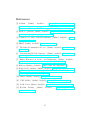
References
[1] Adafruit. [Online]. Available:
<http://learn.adafruit.com/
pi-video-output-using-pygame/overview,http://learn.
adafruit.com/adafruit-ultimate-gps/direct-computer-wiring>.
[2] AlaMode - purchase. [Online]. Available: <http://www.makershed.com/
AlaMode_for_Raspberry_Pi_p/mkwy1.htm>.
[3] Common Core State Standards Initiative, [Online]. Available: <www.
corestandards.org>.
[4] FIRST. [Online]. Available: <www.usfirst.org>.
[5] ”The Linux Documentation Project,” [Online]. Available: <http://www.
tldp.org/>.
[6] ”Understanding RC LiPo Batteries,” [Online]. Available: <http://www.
rchelicopterfun.com/rc-lipo-batteries.html>.
[7] ”Higher Education in Science and Engineering” [Online]. Available:
<http://www.nsf.gov/statistics/seind12/pdf/c02.pdf>.
[8] ROS.org. [Online]¿ Available: <http://www.ros.org/wiki/>.
[9] Raspberry Pi - purchase. [Online]. Available: <http://www.newark.com/
jsp/search/productdetail.jsp?SKU=43W5302’I&’CMP=KNC-GPLA’
I&’mckv=|pcrid|20115736341|plid|>.
[10] SailBot. [Online]. Available: <http://sailbot.org/>.
[11] ”UBC SailBot,” [Online]. Available: <http://ubcsailbot.org/>.
[12] Vex Robotics. [Online]. Available: <http://www.vexrobotics.com/>.
[13] Wyolum Arduino. [Online].
projects/alamode/>.
Available:
27
<http://wyolum.com/
A
Appendix A: Recommended Hardware
The components in Table 1 on page 29 are recommended for a basic, functioning, competitive sailboat.
NOTE: We recommend the Aquacraft Vela as an RC boat because we
have used and tested it – as Mr. Robateau’s body. There are a number of
other RC craft that will work for this copmpetition. Several things come
with the Vela that you need to make sure you have if you get another RC
boat:
• RC transmitter and RC reciever, found at hobby stores or online
• Servos that control the sails and rudder
• Space for placing (relatively waterproof) electronics
SOURCE A CONNECTOR FOR THE ENCODER AND INCLUDE IN
THE TABLE
Additional untested or unsourced things: superbright LEDs, nice wiring
pack that can be worked with minimal tools, recommended tupperware, waterproof connectors (maybe cable clam, maybe pneumatic connectors), conformal
28
Name
Rough
Price
(Dollars)
Link
Aquacraft Vela
Sailboat
350.00
<http://www.amazon.com/
Vela-One-Meter-Sailboat-2-4GHz/dp/B004QJPSX0>
Raspberry Pi
35.00
<http://www.element14.com/community/groups/
raspberry-pi>
AlaMode
Shield
50.00
<http://www.makershed.com/AlaMode_for_
Raspberry_Pi_p/mkwy1.htm>
Edimax
EW-7711USn
Wifi Reciever
20.00
Compare Amazon, Newegg, and/or Walmart for online
prices
Adafruit GPS
3339
40.00
<http://www.adafruit.com/products/746>
Compass
LSM303DLH
6.00
<https://www.sparkfun.com/products/9757>
LSM303
Breakout
Board
24.00
<https://www.sparkfun.com/products/10703>
MA3 Encoder
(wind sensor)
30.00
<http://www.usdigital.com/products/ma3>
Water
Sensor
5.00
<http://www.parts-express.com/pe/showdetl.
cfm?partnumber=320-122>
Total
Leak
560.00
Table 1: Recommended set of base hardware
29
B
Appendix B: Recommended Tools and Materials
A number of basic tools and other materials will aid in the set-up of the boat.
• Dremel and sanding wheels
• Phillips head screwdriver
• flat head screwdriver
• precision blade (i.e. Xacto knife) and spare blades
• utility knife and spare blades
• metal straightedge or ruler
• epoxy (with disposable cups, spoons, and brushes)
• Super glue
• aquarium sealant
• Vaseline
• safety glasses
• gloves (what kind?)
• dust masks
• power drill
• hot glue gun with glue
• soldering iron with flux, thin solder, et cetera
• heatshrink
• wire stripper
• wire cutters (unless the stripper has cutters on it)
C
Appendix C: Quick Start Guide
30
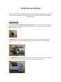
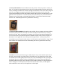
Lets get you up and going! This tutorial will help you setup and test the included hardware and software. It will also give a quick introduction to the organization of the software so you can start writing your own code! Things you’ll need: 1. SD card with the included ROSbian image installed on it. This should have been included in your kit. However, if you did not receive one (or have lost it) check out the guide “Installing ROSbian” before continuing. 2. Raspberry Pi. This will be the “brain” of your Sailbot. It will process the sail position, GPS position of the boat, wind speed and heading and then decide how to move the rudder and sails. 3. A La Mode Board. This board plugs in to the top of the raspberry pi (we’ll show you how) and allows the pi to communicate with all the sensors and servos aboard the boat. 4. Pre-‐wired GPS module. This board detects the GPS position of the boat, with an accuracy of 10m. So if you were to take the boat to your house this module would tell the boat which room it was in, although it would not be accurate enough to know where in the room it was. Using this your boat can navigate to waypoints you define, and avoid obstacles you tell it avoid. We recommend the Adafruit ultimate GPS breakout board, and the pictures and descriptions in this guide will refer to that device. This board comes pretty much set up, but you will still need to solder wires to 4 of the leads on the board before using it. If you have not done this already check out the “Assembling the Sensors” guide before continuing. 5. Pre-‐wired compass module. Although this may not look like any compass you’ve seen before, it still works pretty much the same way. This sensor will tell your boat which way it is facing, North, South, East, West, and anywhere in between. It will let your boat adjust heading into or out of the wind. We recommend the Sparkfun LSM303 compass module, and the images and descriptions in this guide will assume that you are using this device. It comes pretty much assembled, but you will need to solder wires to 4 of the leads on the board before using it. If you have not done this already check out the “Assembling the Sensors” guide before continuing. 6. Encoder. This what you will be using as a wind direction sensor. You’ll attach a wind vane to the brass rod sticking up out of the encoder, which will turn to face the direction of the wind. The encoder returns the angular position of the rod, from 0 to 360 degrees. Now, you might be wondering, “where is 0 degrees? Where is 360 degrees? The rod just keeps turning forever.” Good point! Before using the rod on the boat you will need to calibrate it so that the position it thinks is 0 degrees is the wind vane pointed towards the bow of the boat, and 180 degrees points towards the stern. We’ll you through that in a bit though. 7. 5v Servo. The two servos on your boat allow the brain to move the rudder and sails to the angles it wants. For this guide however, you will need a spare 5V servo. if you did not receive an extra servo in your kit (if you only have the two in the boat) then any 5v servo should work. If you do not have one lying around you can purchase one online at a website like sparkfun.com, or at your local radioshack. 8. 2 Power Blocks. There will be 3 sensors and 2 servos aboard your boat, all which need to be powered from one battery. These little gizmos let you plug many wires into one power port. We’ll show you how they work in a bit. Two should have been included in your kit. 9. A working linux operating system. If you already have some flavor of linux installed on your computer, and would like to use that then just follow the “Setting up Linux for Rosbian Development” guide. However, you can also get a pre-‐configured VM which has all the software and settings you need pre-‐loaded, from [site with our vm]. If you wish to use the VM on a Windows computer follow the brief instructions in the “Setting up Windows to use the linux VM”. Setting up the hardware: 1. Connect everything to the power blocks. Plug power and ground from each sensor into the power blocks. One power block should have all the ground wires plugged into it, and the other should have all the power wires. The GPS module: The compass: The servo: The encoder: pwr gnd pwr gnd pwr gnd gnd Power Signal Plug all the wires into their respective power block (it doesn’t matter which one as long as all the gnds are in one block and all the powers are in another). Also plug a loose wire stripped at both ends, about as long as your hand, into both power blocks. pwr wires gnd wires pwr wire which goes to battery pwr gnd wire which goes to the battery gnd 2. Connect the alamode to the raspberry pi. The alamode fits snug on the top the raspberry pi as shown below. 3. Make sure the power jumper on the alamode is in the off position. The alamode can be powered either by the raspberry pi, or through it’s own power source. When the jumper is in the “on” position (first picture) power comes from the pi. When it is in the “off” position (second picture) it takes power from the microusb power port (shown below), or a battery (explained later). You will always want to power the alamode with it’s own power source, so the jumper should always in the off position. If you don’t do this then the sensors will not get enough power to run properly. The jumper in the “on” position. This is the position you do not want. The jumper in the “off” position. This is the position you do want. The microsusb power port through which you will be powering the alamode. There is also one on the raspberry pi which will also be used to power the pi. 4. Plug in the sensors and the servo. Now we need to plug in our sensors and our servo into the alamode, through which they will communicate with the raspberry pi. First, the GPS. Plug the wire from the TX pin on the GPS into the D3 port on the A La Mode, and the wire from the RX port into D2. RX pin TX p in D3 D2 Next, the compass. Plug a wire from the SCL pin on the compass into port A5 on the A La Mode. Then plug a wire from the SDA pin on the compass into port A4 on the aLaMode. SDA Pin SCL Pin Port A4 Port A5 Now, for the servo. Plug the signal wire from the servo cable into D9. The servo has only three wires running from it, pwr, gnd and signal. Signal wire Now let’s plug in the encoder: Signal wire And finally, plug the power blocks in. Take the loose wire you plugged into the gnd block and plug the other end into one of the two gnd ports shown below. Do the same with the wire from the pwr block, but plug it into the 5V port. Gnd p ower pwr power block block 5. Plug the SD card into the Raspberry Pi. Just slide the SD card into the port on the bottom of the Raspberry pi, as shown below. 6. Plug the Raspberry Pi into the router, then plug in first the aLaMode power, followed by the Raspberry Pi Power. Find a nice level, non-‐metallic surface near three outlets. Plug the two microusb adapters included in the kit into two of the outlets. Plug the included router into the third. If for some reason you don’t have the adapters (you lost them, or never received them) most Android phone chargers will also work. Now plug the pi into the router. Any standard cat5E Ethernet cable will work; one should have been included in your kit. However, if you do not have one you can purchase one online on amazon.com, or any local electronics store (Best Buy, Radio Shack). There should now be lights blinking on the raspberry pi, the aLaMode and the GPS. If you do not see any lights make sure that the micro usb cables are plugged in securely, both to the wall outlet and the boards. Also make sure the outlet you are using works, by plugging something else in and verifying it works. Getting started with the software: Once you get the lights blinking on the raspberry pi, GPS and aLaMode you are ready to get started with the sailboat software. If the steps below I will include screenshots from the pre-‐
configured VM from [website]. If you are not using that VM, but still followed the “Setting up Linux for Rosbian Development”, things might look a bit different, but all the commands should work the same. 1. Boot up your Linux machine (if you don’t have this consult Things you need number 8). 2. Open a terminal window. You will be using the terminal often while developing for code for the Sailbot. You will use it to run ROS locally on your linux machine, for testing, and also to communicate with the Raspberry Pi, and run ROS there. ROS is the software at the core of your Sailbot’s brain. You don’t need to worry about how it works, unless you’re interested. Most of the time you will be editing code which communicates with ROS (we will explain this later), but you will never have to do anything too complicated with it. 3. Type in the command ssh pi@rosbian, and press enter. You may see a warning like:
The authenticity of host 'rosbian1.olin.edu (10.33.26.32)' can't
be established. ECDSA key fingerprint is
b1:56:1e:e5:87:fa:9d:0d:2f:57:46:eb:53:41:1c:7e.
Are you sure you want to continue connecting (yes/no)?
In which case just type yes and hit enter. You will now be asked for a password. The password is raspberry. Type that in and hit enter. 4. You will now see these lines in your console: Debian GNU/Linux comes with ABSOLUTELY NO WARRANTY, to the extent
permitted by applicable law.
Last login: Tue Apr 23 11:10:58 2013 from 10.41.24.174
pi@rosbian1 ~ $
The raspberry pi also runs a version of linux, whose console operates the same way that the console on your version of linux operates. When you run the command ssh pi@rosbian you are telling your computer to send everything you type into your console, to the console on the pi, and then display everything the console on the pi sends back, in your console. The pi@
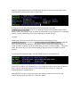
part of the command indicates that you want to login into the raspberry pi as the user named pi (a user which we have created and pre-‐configured for you). So at this point you can consider the console you have open, actually a console for the raspberry pi, and every command you type as a command you are sending to the device, as the user pi. 5. Now run the command roscd sailboat. Your terminal should now look like this: pi@rosbian1 ~/catkin_ws/src/sailbot $
Before you go any further run the command git pull origin master. This updates the sailboat code, to make sure it will work for the next few steps. Now, the main use of a console is to navigate around a computer. The beginning of the line, next to the blinking cursor indicates where in the computer you are. So when you see the line pi@rosbian1 ~/catkin_ws/src/sailbot $
The part that is highlighted blue and green, pi@rosbian1, is the computer and username. So you know that you are logged on as the user pi, on the computer rosbian1 (every computer running Linux has a name, so other computers can talk to it). The part that is highlighted pink ~/catkin_ws/src/sailbot, is the directory you are currently in. If you normally use Windows as your operating system you may have used Windows explorer before, to find or open a file. You use explorer by clicking on pictures of folders to open them, which reveals the files and other folders they contain. With the console you are doing the same thing, but there’s no mouse. You enter a new directory using the command cd (which stands for change directory). However, when you use cd you need to specify which folder you want to change to. So you either memorize the name of every folder on your system (take it from me, don’t try this), or you use another popular command, ls. ls lists all the folders and files in the current directory. So go ahead and try this command now. Just type ls into the terminal and hit enter. You should get something that looks kind of like this: So now you can see all the files and directories contained within the folder ~/catkin/src/sailbot. All the purple words are names of other folders, and the white words are files. Now that we know the names of all the folders we can explore, let’s try changing directory (usually called cding, pronounced ceedeeing). Go ahead and type: cd launch and hit enter. Now the name of your current directory should have gone from ~/catkin_ws/src/sailboat to ~/catkin_ws/src/sailboat/launch. What this means is that you are now inside the folder launch, which is inside folder sailboat, which is inside the folder src which is inside the folder catkin_ws which is inside the folder ~. cding into a folder, like we just did, is just the same as double clicking the picture of a folder in windows explorer. So now type the command ls again, and you should see this (or something like it): So there are no folders in this directory (no purple words). So all these names must be names of files. To get you started we’re gonna run one of these files, we’ll do this by running the command roslaunch calibrate.launch. You might have to wait for a minute, but then you should see some text print out on the console. Now go ahead and follow the “Calibration Guide“. D
Appendix D: CommunicationS Testing with
Arduino
45
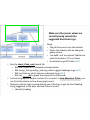
The point of this Guide
In these slides you can follow high-level steps to walk through and
check each step of the code. This will (hopefully) let you
1. Test your system and confirm that it works OR
2. Narrow in on the points in your system that are not working
While this guide will try to give suggestions for what might be going
wrong in your system, we can’t cover the entire range of problems that
might be raising issues here. Hopefully this will help you identify
problem areas, at the very least.
Best of luck!
-- The Olin Robo II Team
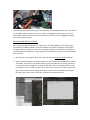
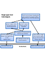
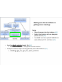
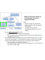
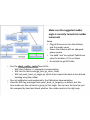
Rough upper level
Code diagram
‘think’ tries to choose a heading that
goes towards the waypoint without
going into irons or directly downwind
‘go fast’ outputs where
not to go (into irons,
directly downwind)
‘maintain_fast_sail_angle’
chooses a sail angle based
on the
apparent wind
Sail servo moves sail
‘go short’ outputs
where to go (at
waypoint)
The Raspberry Pi receives sensor
data from the alaMode
The alaMode receives data
from the sensors
The Real World
‘point_boat_at_target’
tries to use the rudder
to point the boat where
think.py requests
Rudder servo moves rudder
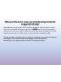
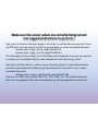
Why doing testing with Arduino <-> Computer is useful, when
you’ll be using Raspberry Pi <-> alaMode in the end
We will need to check whether the code on the Raspberry Pi will work with
the alaMode eventually, but making sure that code on ‘any Arduino’ to ‘any
Computer’ will work is very valuable.
The goal is to make sure the code works on you computer, where you can see
the information very easily. Then you can do testing on the RasPi/alaMode to
make sure it still runs, and you’re doing less testing with the RasPi/alaMode
trying to check whether it’s doing the right thing.
Example: If the boat is supposed to take the apparent wind and use that
to set the sail to an angle that you want, it can be hard to test that with
everything plugged into the Raspberry Pi. If you run the code and the sail
doesn’t do what you expect, there are a number of places problems can
be happening (in a sensor, in the code, or in the servo wiring, etc.)
If instead you plug the wind sensor into your computer, you can
easily check that 1) the sensor data is reaching the computer, 2) the code
is choosing to do the right thing with the sensor data, and finally 3) that
the sail servo is moving to the right place.
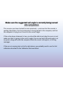
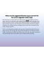
How to use the Index
The suggestions we make in these slides and commands we suggest
running may be unfamiliar to you (like ‘Rostopic echo the topics you
care about’) so we have tried to tried to create an index at the end
explaining various steps. If a topic is in the index, we will mark it like so.
Topic of interest [A1]
Another topic of interest [A2]
The index will either try to explain the topic or point you to other
resources in our documentation.
If a confusing suggestion is not marked as a topic, it was probably
marked in an earlier slide (if it came up before) and you will likely be
able to find it in the Index.
How to use the Results Slides
After each test slide, you’ll find a results slide that will try to explain
what information you should be seeing.
These slides will also try to give you some ideas for solutions if you’re
not seeing the correct thing.
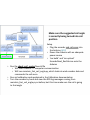
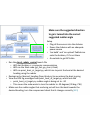
Making sure that an Arduino is
getting sensor readings
Setup
• Plug all sensors into the Arduino [A1]
• Power the Arduino with an adequate
power source [A2]
• ‘ino build’ and ‘ino upload’ PubSub.ino
onto Arduino, if it’s not there [A3]
• Run the check_arduino launch file [A4]
• Will start Arduino <-> computer communication
• Rostopic echo the topics coming directly out of the Arduino [A5]
• /heading, /gps_lat, /gps_lon, /pwm_duration
Making sure that an Arduino is getting sensor readings
/heading should be a number from 0-360, and should change when you spin the
compass. If you are seeing non-linearity (for example, if the actual compass changes
10° and the reading jumps 180°) then you need to run the compass calibration
explained in the Calibration documentation.
/gps_lat and /gps_lon should be 0 inside and something like 42.288802, -71.308823
outside. You can check a site like http://itouchmap.com/latlong.html to check your
actual latitude and longitude. Use the tutorials mentioned in Index A11 to
troubleshoot GPS issues.
/pwm_duration should be a number from 0 to 1027 that increases as you spin the
encoder, then jumps back to 0 when you cross 1027.
In general, if any sensors aren’t working it is a good idea to
1. Double check the wiring making sure everything is connected properly and
there are no shorts or other problems in the system
2. Use a multimeter to measure the voltage being supplied to the sensors and
make sure it is correct
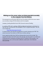
Making sure the sensor values are
being reported accurately to the
computer from the Arduino
Setup
• Plug all sensors into the Arduino
• Power the Arduino with an adequate
power source
• ‘ino build’ and ‘ino upload’ PubSub.ino
onto Arduino, if it’s not there
• Run the check_sensor_data launch file
• Will start Arduino <-> computer communication
• Will start publishing the visible sensor data [A6]
• Rostopic echo the topics holding the processed sensor data [A7]
• /compass_heading, /y_position_UTM, /x_position_UTM, /wind_angle
Making sure the sensor values are being reported accurately
to the computer from the Arduino
The comments here will assume that the last test worked, and that the sensor values
are accurately coming off of the Arduino onto the computer.
/compass_heading should be from 0-360, the exact same as /heading
/y_position_UTM and /x_position_UTM should be the longitude (x) and latitude (y)
from the GPS, converted into UTM. Wikipedia ‘UTM’ for a good description. You can
use a site like this:
http://tagis.dep.wv.gov/convert/
To check whether your latitude and longitude is correctly showing up as UTM. The
actual conversion from lat/lon to UTM occurs in latlon_tools.py.
/wind_angle should be from 0-360, and change when you spin the encoder. The
computer has taken the 0-1027 scale of the raw data and converted it to a 0-360 scale.
If the wind vane is mounted on the boat and the ‘0’ position of the encoder is not
dead ahead, you can run the encoder calibration mentioned in the Calibration
documentation.
Make sure the sensor values are
correctly being turned into a
suggested sail angle
Setup
• Plug the encoder into the Arduino
• Power the Arduino with an adequate
power source
• ‘ino build’ and ‘ino upload’
EncoderRead_RosPub.ino onto the
Arduino
• Run the check_sail_control launch file
• Will start Arduino <-> computer communication
• Will run maintain_fast_sail_angle.py, which looks at wind encoder data and
commands the sail servo
• Spin encoder by hand to an angle you know the correct sail position for [A8] and
check with Log messages [A9] that program is trying to set the correct sail angle
• Look for Log messages from maintain_fast_sail_angle.py, which look like so:
• fast_sail_angle.py: sail angle should be: 60
• This means the code wants to set the sails 60 degrees out – is that correct for
the current encoder angle
Make sure the sensor values are correctly being turned into
a suggested sail angle
Index A8 (How you know what the sail position should be) tells you what to expect
from the commanded sail setpoint. Because the sail position is set by the apparent
wind, you can spin the encoder to different positions by hand and make sure that the
angle the code wants to set the sail to are correct (correct according to A8).
The log messages in maintain_fast_sail_angle.py should let you see what the apparent
wind angle is. This could be useful for debugging, if the sail angle that
maintain_fast_sail_angle.py wants to create is not what you expect.
Make sure the suggested sail angle
is correctly being turned into sail
position
Setup
• Plug the encoder and sail servo into
the Arduino [A10]
• Power the Arduino with an adequate
power source
• ‘ino build’ and ‘ino upload’
EncoderRead_RosPub.ino onto the
Arduino
• Run the check_sail_control launch file
• Will start Arduino <-> computer communication
• Will run maintain_fast_sail_angle.py, which looks at wind encoder data and
commands the sail servo
• Run sail calibration code explained in the Calibration documentation
• Turn the encoder by hand and view the ROS log messages coming from
maintain_fast_sail_angle.py as before, but this time make sure the sail is going
to that angle
Make sure the suggested sail angle is correctly being turned
into sail position
This assumes you have checked the tests previously – you know that the encoder is
reading information, that that information is being passed to the computer, and that
the computer is trying to set the sail to the correct angle.
If the entire above statement is true, you should be able to just plug the servo in and
make sure that it is going to the correct angles. You can see what the wind angle is at
any point, along with what the computer thinks the correct sail angle is, in the Log
messages.
If the servo is moving, but not to the right places, you probably need to run the Sail
calibration described in the Calibration documentation.
Make sure the sensor values are
correctly being turned into
suggested directions to go
Setup
• Plug all the sensors into the Arduino
• Power the Arduino with an adequate
power source
• ‘ino build’ and ‘ino upload’ PubSub.ino
onto the Arduino, if it’s not there
• Go outside to get GPS data [A11]
• Run the check_think_code launch file
• Will start Arduino <-> computer communication
• Will run go_fast.py and go_short.py, which suggest headings to go [A12]
• Will run think.py, which chooses a direction to go [A13]
• Will run _____.py to graph the output of the think code
• Look at the graphical output, and see if it is correct. In How Robateau Thinks, you
can find information on how these graphs work
• Rostopic echo the topic coming directly out of think.py to get the final heading
being suggested to the boat, and see if that is correct
• /desired_heading
Make sure the sensor values are correctly being turned
into suggested directions to go
This assumes you have done tests 1 and 2 – the computer can see all the correct
sensor data.
Inside of How Robateau Thinks documentation, you can see pictures of what
go_fast.py, go_short.py, and think.py should all look like. In general (this will make
more sense when you look at the pictures) go_short.py will create an oblong oval with
a maximum pointing at the next waypoint, go_fast.py will have a thick wedge pointing
upwind, and a thin wedge pointing downwind. think.py will be the combination of
those two graphs.
When you ‘rostopic echo /desired_heading’, you should see a value from 0-360, and it
should correspond with the highest point on think.py.
Make sure the sensor values are correctly being turned
into suggested directions to go (cont.)
If go_short is all zeros (the polar graph is all white) it could be because you don’t have
any GPS data. You can plug in the GPS to get real data, or create simulated data with:
rostopic pub -1 /gps_lat std_msgs/Float64 0.0
rostopic pub -1 /gps_lon std_msgs/Float64 0.0
This will make your boat think it is at 0 latitude and 0 longitude. If you set up a mission
in mission_file.csv (Index A14) the code should then have data for go_short.
If go_fast is all ones (there is a blue ring on the polar graph) it’s most likely because
you don’t have wind data. Either plug in the encoder (or test it if it’s in) or create
simulated data with:
rostopic pub -1 /pwm_duration std_msgs/UInt16 128
This is on a 0-1023 scale, where 256 is 90°, 512 is 180°, etc. This should make your
boat ‘see’ an apparent wind, which should give go_fast enough data to work with.
Make sure the suggested direction
to go is turned into the correct
suggested rudder angle
Setup
• Plug all the sensors into the Arduino
• Power the Arduino with an adequate
power source
• ‘ino build’ and ‘ino upload’ PubSub.ino
onto the Arduino, if it’s not there
• Go outside to get GPS data
• Run the check_rudder_control launch file
• Will start Arduino <-> computer communication
• Will run the think code (go_fast, go_short, think)
• Will run point_boat_at_target.py, which tries to point the boat at the desired
heading using the rudder
• Rostopic echo /desired_heading (from think.py) to see where the boat is going
• View the ROS log messages from point_boat_at_target.py, which look like
• point_boat_at_target.py: rudder angle is being set to: -30
• This means the code wants to turn the rudder to -30 degrees (30 deg. CW)
• Make sure the rudder angles that are being set will turn the boat towards the
desired heading, turn the compass and check that it changes correctly [A15]
Make sure the suggested direction to go is turned into
the correct suggested rudder angle
Index A15 (How you know what the rudder position should be) tells you what to
expect from the commanded rudder setpoint. Because the rudder depends on the
output of think.py, you can ‘rostopic echo /desired_heading’ to check where think
wants the boat to go, then spin the boat by hand and make sure that the rudder is
resetting as the compass direction changes. You can check the correctness of the
rudder setting using A15.
If this is not doing what you expect you may need to dig back into what think.py is
doing, then go_short and go_fast, then all the way back into the GPS and compass
values. As you get errors farther and farther out in the code, you need to work your
way back through every intermediate step to double check everything.
Make sure the suggested rudder
angle is correctly turned into rudder
movement
Setup
• Plug all the sensors into the Arduino,
and the rudder servo
• Power the Arduino with an adequate
power source
• ‘ino build’ and ‘ino upload’ PubSub.ino
onto the Arduino, if it’s not there
• Go outside to get GPS data
• Run the check_rudder_control launch file
• Will start Arduino <-> computer communication
• Will run the think code (go_fast, go_short, think)
• Will run point_boat_at_target.py, which tries to point the boat at the desired
heading using the rudder
• Run sail calibration code explained in the Calibration documentation
• View the ROS Log messages from point_boat_at_target.py, as before, but this
time make sure the sail servo is going to that angle. You can turn the boat (or just
the compass) by hand and check whether the rudder reacts in the right way.
Make sure the suggested rudder angle is correctly
turned into rudder movement
This assumes you have checked the tests previously – you know that the sensors are
reading information, that that information is being passed to the computer, that the
think code is choosing reasonable headings, and that the computer is trying to set the
rudder to the correct angle.
If the entire above statement is true, you should be able to just plug the rudder servo
in and make sure that it is going to the correct angles. You can see what the desired
heading is at any point, along with what the computer thinks the correct rudder angle
is, in the Log messages.
If the servo is moving, but not to the right places, you probably need to run the
Rudder calibration described in the Calibration documentation.
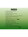
INDEX
A1: Plugging sensors into the Arduino
A2: Powering the Arduino
A3: Using ino to put code on the Arduino
A4: Running a launch file
A5: Using ‘rostopic echo’ to query your code for information
A6: What it means to publish data to a topic
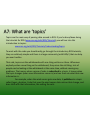
A7: What are ‘topics’
A8: How you know what the sail position should be
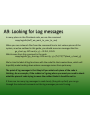
A9: Looking for Log messages
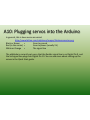
A10: Plugging servos into the Arduino
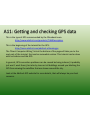
A11: Getting and checking GPS data
A12: What go_fast.py and go_short.py are doing
A13: What think.py does
A14: How are missions set with mission_file.csv
A15: How you know what the rudder position should be
A1: Plugging sensors into the Arduino
You can see details about setting up and plugging in the Sensors section of the main
Olinoboat documentation, and also in the Quick Start guide.
Be careful with which wires are plugged where, because if a wire is plugged into
Digital Port 7 on the alaMode, and the computer thinks it is plugged into Digital Pin 6,
then whatever sensor is plugged into the wrong pin will not be seen at all by the
computer.
A2: Powering the Arduino
Powering an Arduino can be done a couple of ways:
• From your computer, via a USB cable
• Using 9V batteries with a barrel plug
• Using a DC adapter with a barrel plug
This tutorial is rather old, but it has lots of good pictures. If you’re interested in how
to power the Arduino, skip down to the ‘Power Up!’ section. Ignore all instructions
regarding jumper-settings, modern Arduinos, like the very common Uno, have no
need for this.
http://www.ladyada.net/learn/arduino/lesson0.html
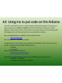
A3: Using ino to put code on the Arduino
From the command line in Linux (look through the Quick Start guide if that phrase is
new to you) you can build and upload code onto the Arduino using a set of tools
called ino. This is very useful in Linux, and it is necessary when you start working with
the Raspberry Pi, which usually only has a command line interface.
You can download the ino toolkit for your computer here:
http://inotool.org/
The ‘pip install ino’ command is easiest.
To upload code on the Arduino you navigate into the folder of the code you want to
run (for example into the PubSub folder) and run
ino build
ino upload
You can find a good tutorial here:
http://inotool.org/quickstart
Eventually, to upload Arduino code onto the alaMode, you will have to run
ino build –m alamode
ino upload –m alamode –p /dev/S0
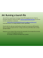
A4: Running a launch file
Launch files are a good way of running multiple ROS programs at once. If you’ve
done/been doing the tutorials for ROS ( www.ros.org/wiki/ROS/Tutorials) you will run
into this introduction to roslaunch:
http://www.ros.org/wiki/ROS/Tutorials/UsingRqtconsoleRoslaunch
Scroll down to the ‘1.2.2 Using roslaunch’ section, specifically
To work with the code you should really go through the introductory ROS tutorials,
they are relatively simple and there is a large community (with FAQs!) that can help
you over hurdles.
Simply put, to run a launch file you type this command in the command line terminal
roslaunch PackageName LaunchFile
For example, roslaunch Olinoboat check_arduino
A5: Using ‘rostopic echo’ to query your
code for information
Topics are the main way of passing data around in ROS, and ‘rostopic echo‘ is a way
that the programmer (you!) can view what is currently on a topic. If you’ve
done/been doing the tutorials for ROS (www.ros.org/wiki/ROS/Tutorials) you will run
into this introduction to rostopic:
www.ros.org/wiki/ROS/Tutorials/UnderstandingTopics
To work with the code you should really go through the introductory ROS tutorials,
they are relatively simple and there is a large community (with FAQs!) that can help
you over hurdles.
A6: What it means to publish data to
a topic
Topics are the main way of passing data around in ROS. If you’ve done/been doing
the tutorials for ROS (www.ros.org/wiki/ROS/Tutorials) you will run into this
introduction to topics:
www.ros.org/wiki/ROS/Tutorials/UnderstandingTopics
To work with the code you should really go through the introductory ROS tutorials,
they are relatively simple and there is a large community (with FAQs!) that can help
you over hurdles.
That said, publishing to a topic means a piece of code will take information that it has
(like the GPS position of the boat) and ‘post’ that information for other code to see.
You can see more details of the ‘posting’ process in the next slide, talking about
topics.
A7: What are ‘topics’
Topics are the main way of passing data around in ROS. If you’ve done/been doing
the tutorials for ROS (www.ros.org/wiki/ROS/Tutorials) you will run into this
introduction to topics:
www.ros.org/wiki/ROS/Tutorials/UnderstandingTopics
To work with the code you should really go through the introductory ROS tutorials,
they are relatively simple and there is a large community (with FAQs!) that can help
you over hurdles.
That said, topics are like whiteboards with one thing written on them. Whenever
anybody writes a new thing on the whiteboard, they erase the old thing. Lots of
people can be looking at the whiteboard at the same time, without causing any
problems. That means when a piece of code is subscribed to a topic, it knows when
the topic changes (when new information comes in) and can then see what that new
information is.
For example, when the wind sensor gets new data, it publishes to a topic
called /pwm_duration. Code that uses the wind sensor data notices that change, and
does stuff with that information, like setting the sails.
A8: How you know what the sail position
should be
As of 04/25/13, the sails were set according to the apparent wind angle. That means
if the wind appears on the wind sensor to be 45° off the bow, the sails will be set to
what we thought was an appropriate angle (0° = full in, and 90° = full out).
In the program maintain_fast_sail_angle.py, you can find a lookup table that contains
1. A list of points of sail (points_of_sail = [0, 45, 60, 90, 135, 180])
2. The angle of the sail that we thought was appropriate for that point of sail
(sail_points = [0, 0, 15, 40, 60, 80])
This is explained more in the How Robateau Thinks documentation, but essentially
when the wind is 60° off the bow in either direction (the 3rd element in the
points_of_sail variable) then the boat will try to set the sail to 15° out (the 3rd
element of sail_points).
A9: Looking for Log messages
In many places in the Olinoboat code, we use the command
rospy.loginfo(stuff_we_want_to_user_to_see)
When you run roslaunch files from the command line to test various pieces of the
system, as we’ve outlined in this guide, you should see error messages like this:
go_short.py: GPS sent (x, y) = 31352, 12341
Which came from this command in the code
rospy.loginfo("go_short.py: GPS sent (x, y) = (%f, %f)" %(boat_x, boat_y))
We’ve tried to label all log functions with the code file that creates them, which will
hopefully make tracking down where a message comes from quite easy.
The point of log messages is that they tell you what each piece of the code is
thinking. As an example, if the rudder isn’t going where you want you need to check
what the piece of code trying to move the rudder thinks it should be set to.
If there are too many log messages to read clearly (they pile up fast) you can go
through the code and comment out the log messages you aren’t using.
A10: Plugging servos into the Arduino
In general, this is how servos are wired:
http://www.fatlion.com/sailplanes/images/futabaconnector.png
Black or Brown
=
Goes to ground
Red (in the center) =
Goes to power (usually 5V)
White or Orange =
The signal line
The alaMode is currently set up so that the Rudder signal line is on Digital Pin 9, and
the Sail signal line plugs into Digital Pin 10. You can see more about setting up the
servos in the Quick Start guide.
A11: Getting and checking GPS data
This is the type of GPS recommended by the Olinoboat team:
http://www.adafruit.com/products/746#Description
This is the beginning of the tutorial for the GPS:
http://learn.adafruit.com/adafruit-ultimate-gps
The ‘Direct Computer Wiring’ link at the bottom of the page will take you to the
next part of the tutorial, that can be somewhat unclear. This tutorial can be done
with an Arduino and the GPS.
In general, GPS connection problems can be caused be being indoors (it probably
just won’t work there), but also by trees or tall buildings around you blocking the
GPS from viewing the satellites that are strewn around the sky.
Look at the Adafruit GPS website for more details, that will always be your best
resource.
A12: What go_fast.py and go_short.py
are doing
The programs go_fast and go_short try and do simple tasks, but the way that simple
task is done can be a bit hard to grasp.
go_fast looks at the apparent wind angle, then tells the boat it should not into irons
or directly downwind. As of 04/25/13, that means it doesn’t want to go within 50° on
either side of the wind angle, or within 10° of directly downwind. These numbers can
be changed by other teams.
go_short looks at the GPS position of the boat and the GPS position of the next
waypoint, and tells the boat it should be pointing at the next waypoint.
How this is done, and how to interpret the graphical output of go_short and go_fast
correctly, can be seen in the How Robateau Thinks documentation.
A13: What think.py does
This the documentation at the top of think.py
# think.py creates a loop that calls other code
#
# Dependent on : go_fast.py, go_short.py
# think.py takes the outputs of go_fast and go_short, multiplies them together,
and then chooses the strongest element as the heading to go to
# See code explanation documentation for a more in-depth explanation of the
arbiter
As stated, you can see the Code Explanation documentation for a more in-depth
look at think.py, but at it’s heart think.py takes the suggestions of go_fast and
go_short and from those suggestions chooses a way to go. Understanding go_fast
and go_short well is necessary to predict what think.py will do.
For example if the next waypoint is N, but there is wind coming from the NE,
go_fast will say “don’t go into irons” and go_short will say “go straight to the
waypoint”. think.py will try to mix both suggestions, and should choose NNW, which
will later turn into a SSE tack.
A14: How are missions set with
mission_file.csv
Inside of the upper level Olinoboat folder, there should be both mission_file.csv and
mission_file_csv_howto.txt. The txt file explains how to set waypoints for the boat
using mission_file.csv. Here is the overview:
Inside of mission_file.csv you should see something like
1, 0, 42, -71
1, 0, 42.00001, -71.00001
This corresponds to
'type of mission', 'information passing parameter', 'goal_latitude', 'goal_longitude‘
The boat will try to sail to the (latitude, longitude) point (42, -71), then the point
(42.00001, -71.00001)
A15: How you know what the rudder
position should be
As of 04/25/13, the rudder is set to try and point the boat at the desired compass
heading. That means if the boat is pointing South, and the heading is West, the boat
needs to turn -90° (assuming that North = 0° and degrees increase clockwise, as all of
the Olinoboat code assumes). The rudder is stopped in code from going more than
45° to either side, assuming that the rudder calibration described in the Calibration
documentation has been run, which means the rudder should try to go to -45° (full
CW, which should turn the boat to port).
If the next waypoint is 30° off the starboard bow, the rudder should try to go to the
30° point. That means the rudder will spin 30° CCW, turning the boat to starboard so
it will point at the waypoint.
The code that determines this response is in point_boat_at_target.py, which has a fair
amount of documentation in the code itself trying to explain how this is done.