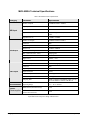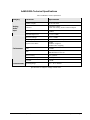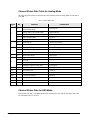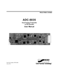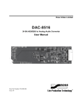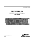
1
Ross Video Limited
MUX-8552A(-C)
AES/EBU Embedder/Multiplexer
User Manual
Ross Part Number: 8552ADR-004
Issue: 01
MUX-8552A • AES/EBU Embedder/Multiplexer User Manual
•
•
•
Ross Part Number: 8552ADR-004
Document Issue: 01
Printed in Canada.
The information contained in this User Manual is subject to change without notice or obligation.
Copyright
© 2007 Ross Video Limited. All rights reserved.
Contents of this publication may not be reproduced in any form without the written permission of Ross
Video Limited. Reproduction or reverse engineering of copyrighted software is prohibited.
Notice
The material in this manual is furnished for informational use only. It is subject to change without
notice and should not be construed as a commitment by Ross Video Limited. Ross Video Limited
assumes no responsibility or liability for errors or inaccuracies that may appear in this manual.
Trademarks
•
•
•
is a registered trademark of Ross Video Limited.
Ross, ROSS, ROSS ®, and MLE are registered trademarks of Ross Video Limited.
All other product names and any registered and unregistered trademarks mentioned in
this manual are used for identification purposes only and remain the exclusive property
of their respective owners.
Important Regulatory and Safety Notices
Before using this product and any associated equipment, refer to the “Important Safety Instructions”
listed below so as to avoid personnel injury and to prevent product damage.
Products may require specific equipment, and /or installation procedures be carried out to satisfy
certain regulatory compliance requirements. Notices have been included in this publication to call
attention to these Specific requirements.
Symbol Meanings
This symbol on the equipment refers you to important operating and maintenance
(servicing) instructions within the Product Manual Documentation. Failure to heed
this information may present a major risk of damage or injury to persons or
equipment.
The symbol with the word “Warning” within the equipment manual indicates a
potentially hazardous situation, which if not avoided, could result in death or serious
injury.
Warning
The symbol with the word “Caution” within the equipment manual indicates a
potentially hazardous situation, which if not avoided, may result in minor or
moderate injury. It may also be used to alert against unsafe practices.
Caution
The symbol with the word “Notice” within the equipment manual indicates a
situation, which if not avoided, may result in major or minor equipment damage or a
situation which could place the equipment in a non-compliant operating state.
Notice
This symbol is used to alert the user that an electrical or electronic device or
assembly is susceptible to damage from an ESD event.
ESD
Susceptibility
Important Safety Instructions
Caution
This product is intended to be a component product of the RossGear 8000A series
frame. Refer to the RossGear 8000A series frame User Manual for important safety
instructions regarding the proper installation and safe operation of the frame as well
as it’s component products.
Warning
Certain parts of this equipment namely the power supply area still present a safety
hazard, with the power switch in the OFF position. To avoid electrical shock,
disconnect all A/C power cords from the chassis' rear appliance connectors before
servicing this area.
Service barriers within this product are intended to protect the operator and service
personnel from hazardous voltages. For continued safety, replace all barriers after
any servicing.
Warning
This product contains safety critical parts, which if incorrectly replaced may present
a risk of fire or electrical shock. Components contained within the product’s power
supplies and power supply area, are not intended to be customer serviced and should
be returned to the factory for repair.
To reduce the risk of fire, replacement fuses must be the same type and rating.
Only use attachments/accessories specified by the manufacturer.
EMC Notices
US FCC Part 15
This equipment has been tested and found to comply with the limits for a class A Digital device,
pursuant to part 15 of the FCC Rules. These limits are designed to provide reasonable protection
against harmful interference when the equipment is operated in a commercial environment. This
equipment generates, uses, and can radiate radio frequency energy and, if not installed and used in
accordance with the instruction manual, may cause harmful interference to radio communications.
Operation of this equipment in a residential area is likely to cause harmful interference in which case
users will be required to correct the interference at their own expense.
Changes or modifications to this equipment not expressly approved by Ross Video
Ltd. could void the user’s authority to operate this equipment.
Notice
CANADA
This Class “A” digital apparatus complies with Canadian ICES-003.
Cet appareil numerique de classe “A” est conforme à la norme NMB-003 du Canada.
EUROPE
This equipment is in compliance with the essential requirements and other relevant provisions of CE
Directive 93/68/EEC.
INTERNATIONAL
This equipment has been tested to CISPR 22:1997 along with amendments A1:2000 and A2:2002 and
found to comply with the limits for a Class A Digital device.
This is a Class A product. In domestic environments this product may cause radio
interference in which case the user may have to take adequate measures.
Notice
Maintenance/User Serviceable Parts
Routine maintenance to this RossGear product is not required. This product contains no user
serviceable parts. If the module does not appear to be working properly, please contact Technical
Support using the numbers listed under the “Contact Us” section on the last page of this manual. All
RossGear products are covered by a generous 5-year warranty and will be repaired without charge for
materials or labor within this period. Refer to the section, “Warranty and Repair Policy” in this
manual for details.
Environmental Information
The equipment that you purchased required the extraction and use of natural resources for its
production. It may contain hazardous substances that could impact health and the environment.
To avoid the potential release of those substances into the environment and to diminish the need for
the extraction of natural resources, Ross Video encourages you to use the appropriate take-back
systems. These systems will reuse or recycle most of the materials from your end-of-life equipment in
an environmentally friendly and health conscious manner.
The crossed-out wheeled bin symbol invites you to use these systems.
If you need more information on the collection, reuse, and recycling systems, please contact your local
or regional waste administration.
You can also contact Ross Video for more information on the environmental performances of our
products.
Contents
Introduction
1-1
In This Chapter .......................................................................................................................1-1
A Word of Thanks....................................................................................................1-1
MUX-8552A Overview............................................................................................1-2
MUX-8552A-C Overview........................................................................................1-2
Features ....................................................................................................................1-3
Functional Block Diagram .......................................................................................1-4
Documentation Terms ..............................................................................................1-4
Installation and Setup
2-1
In This Chapter .......................................................................................................................2-1
Static Discharge........................................................................................................2-1
Unpacking ................................................................................................................2-1
Board Installation .....................................................................................................2-2
BNC Labels ..............................................................................................................2-2
MUX-8552A Cable Connections .............................................................................2-2
MUX-8552A-C Cable Connections .........................................................................2-3
User Controls
3-1
In This Chapter .......................................................................................................................3-1
MUX-8552A Jumper Locations ...............................................................................3-2
MUX-8552A-C Jumper Locations ...........................................................................3-3
MUX-8552A-C Gain Adjustment ............................................................................3-4
LEDs.........................................................................................................................3-5
SMPTE 269M Fault Reporting
4-1
In This Chapter .......................................................................................................................4-1
Overview ..................................................................................................................4-1
Jumper Setup ............................................................................................................4-2
Frame Connections...................................................................................................4-2
Details.......................................................................................................................4-2
Upgrades
5-1
In This Chapter .......................................................................................................................5-1
Equipment Supplied .................................................................................................5-1
Upgrade Procedures .................................................................................................5-1
MUX-8552A User Manual (Iss. 01)
Contents • i
Specifications
6-1
In This Chapter ...................................................................................................................... 6-1
MUX-8552A Technical Specifications ................................................................... 6-2
AAM-8552A Technical Specifications ................................................................... 6-3
Channel Status Data Table for Analog Mode.......................................................... 6-4
Channel Status Data for AES Mode ........................................................................ 6-4
Service Information
7-1
In This Chapter ...................................................................................................................... 7-1
Troubleshooting Checklist....................................................................................... 7-1
Warranty and Repair Policy .................................................................................... 7-2
Ordering Information
8-1
In This Chapter ...................................................................................................................... 8-1
ii • Contents
MUX-8552A User Manual (Iss. 01)
Introduction
In This Chapter
This chapter contains the following sections:
•
A Word of Thanks
•
MUX-8552A Overview
•
MUX-8552A-C Overview
•
Features
•
Functional Block Diagram
•
Documentation Terms
A Word of Thanks
Congratulations on purchasing the Ross Video MUX-8552A, AES/EBU Embedder/Multiplexer.
The MUX-8552A family is part of a full line of RossGear Digital products, backed by Ross Video’s
experience in engineering and design expertise since 1974.
You will be pleased at how easily your new MUX-8552A fits into your overall working environment.
Equally pleasing is the product quality, reliability, and functionality. Thank you for joining the evergrowing group of worldwide satisfied Ross Video customers!
We recommend that you read the sections in this User Manual that are relevant to your particular
card(s) before installation. In this way you will ensure its proper integration into your facility and
maximize the features and functionality of the card.
This manual provides installation and operational instructions for both the MUX-8552A and the
MUX-8552A-C versions. Should you have a question pertaining to the operation of your MUX8552A or MUX-8552A-C, please contact us at the numbers listed on the back cover of this
publication. Our technical support staff is always available for consultation, training, or service.
MUX-8552A User Manual (Iss. 01)
Introduction • 1-1
MUX-8552A Overview
The RossGear MUX-8552A AES/EBU Embedder/Multiplexer is a broadcast quality embedder. The
MUX-8552A will embed two 48kHz AES-3id streams (1 group) and output two copies of the
embedded SDI signal. The RossGear MUX-8552A is for use in 75-ohm coaxial AES3id and SMPTE
276M systems .
An SDI signal and 1 or 2 AES-3id signals are input through BNC connectors on the rear of the frame.
The MUX-8552A accepts both 525 and 625 format (SMPTE 259M-C) signals at 270Mb/s. Visual
indicators on the card edge provide indication of the presence of SDI and AES inputs. The MUX8552A provides automatic equalization for 305m of Belden 8281 cable. Two SDI outputs are
provided.
The MUX-8552A can embed one AES group into any one of the four AES groups available. The
group to be embedded is selected via a card edge jumper. Front panel LED’s provide information on
which groups are present in the outgoing SDI stream. The ability to overwrite an incoming group is
available through jumper selection. The MUX-8552A can report a variety of AES signal errors
including: no lock, biphasic coding, parity, CRC check, sample slip, and validity errors. These errors
are indicated on a card edge (Error) LED. In addition, there is SMPTE 269M fault reporting output to
the backplane of the Ross digital rack frame.
The MUX-8552A is also available as the MUX-8552A-C version. The -C version comes preassembled from the factory with the AAM-8552A A/D daughter card, and the CON-8552 analog audio
connector adapter. This provides four balanced analog audio inputs instead of the AES digital audio
inputs.
The MUX-8552A fits into the Ross DFR-8110A or DFR-8104A digital frames. It provides system
builders the ability to easily embed digital audio in an SDI facility. Designed and manufactured to
meet the highest quality broadcast industry standards, the RossGear MUX-8552A is an ideal, cost
effective solution for digital and analog audio multiplexing requirements in your facility.
The MUX-8552A also fits Leitch* 6800 series frames.
MUX-8552A-C Overview
The RossGear MUX-8552A-C version, which comprises the MUX-8552A, the AAM-8552A
(daughter card), and the companion CON-8552 analog audio connector adapter is a broadcast quality
modular product used to allow four analog audio channels to be embedded into a 525 or 625 SDI
stream. The AAM-8552A is a daughter card that plugs onto the top of the MUX-8552A RossGear
AES multiplexer card. The CON-8552 is a connector adaptor that attaches to the rear of the Ross
DFR-8110A or DFR-8104A digital frame.
The AAM-8552A uses state of the art analog to digital converters that provide 24-bit resolution.
Coarse level adjustment jumpers (18dB or 24dB) and fine adjustment potentiometers are provided to
precisely match the converter to your facility’s house reference audio level.
The MUX-8552A-C is part of a growing line of RossGear AES solutions, including distribution,
conversion and monitoring. Designed and manufactured to meet the highest quality broadcast industry
standards, the RossGear MUX-8552A-C is an ideal, cost effective solution for digital and analog audio
multiplexing requirements in your facility.
*
Leitch is a trademark of Leitch Technology Corporation
1-2 • Introduction
MUX-8552A User Manual (Iss. 01)
Features
The following features make the MUX-8552A the most versatile AES/EBU Embedder/Multiplexer
card for your professional audio-video requirements:
MUX-8552A Features
•
•
•
•
•
•
•
•
•
•
•
•
•
Compliance with SMPTE 272M-A 48kHz 20-bit
Automatic 525/625 input video format detection
AES sample rate conversion
Jumper selectable EDH insertion
Auto cable equalization up to 305m of Belden 8281
Visual indication of signal presence
Visual indication of an error condition
Visual indication of AES groups present
SMPTE fault reporting in accordance with SMPTE 269M
Conformity to AES-3id 2001
Two SDI video outputs
5-year warranty
Compatible with Ross 8100 series and Leitch 6800 series frames
MUX-8552A-C Features
•
•
MUX-8552A User Manual (Iss. 01)
AAM-8552A daughter card
o 24-bit ADC resolution
o Selectable maximum input level from -15dBu to -27dBu
o + 0.05 dB frequency response 20 Hz to 22 kHz
o 5-year warranty
CON-8552 analog audio connector adapter
o 2 balanced analog stereo input channels
o 5-year warranty
o Compatible with Ross DFR-8110A-C and DFR-8104A-C frames
Introduction • 1-3
Functional Block Diagram
Figure 1. Simplified Block Diagram of MUX-8552A(-C)
Documentation Terms
The following terms are used throughout this guide:
1-4 • Introduction
•
“Frame” refers to the DFR-8104A and DFR-8110A frames that house the MUX8552A card.
•
All references to the DFR-8104A and DFR-8110A also include the
DFR-8104A-C and DFR-8110A-C versions with the cooling fan option. See the
respective User Manuals for details.
•
“Operator” and “User” both refer to the person who uses the MUX-8552A.
•
“Board”, “Card”, and “Module” all refer to the MUX-8552A board itself,
including all components and switches.
•
“System” and “Video system” refer to the mix of interconnected production and
terminal equipment in which the MUX-8552A operates.
•
“525-line mode” refers to broadcast situations using NTSC composite (analog)
signal reference inputs.
•
“625-line mode” refers to broadcast situations using PAL-B composite (analog)
signal reference inputs. All references to PAL in this manual imply that PAL-B is
being used.
MUX-8552A User Manual (Iss. 01)
Installation and Setup
In This Chapter
This chapter contains the following sections:
•
Static Discharge
•
Unpacking
•
Board Installation
•
BNC Labels
•
MUX-8552A Cable Connections
•
MUX-8552A-C Cable Connections
Static Discharge
Whenever handling the MUX-8552A and other related equipment, please observe all static discharge
precautions as described in the following note:
ESD
Susceptibility
Static discharge can cause serious damage to sensitive
semiconductor devices. Avoid handling circuit boards in high
static environments such as carpeted areas, and when wearing
synthetic fiber clothing. Always exercise proper grounding
precautions when working on circuit boards and related
equipment.
Unpacking
Unpack each MUX-8552A from the shipping container and check the contents to ensure that all items
are included. If any items are missing or damaged, contact your sales representative or Ross Video
directly.
MUX-8552A User Manual (Iss. 01)
Installation and Setup • 2-1
Board Installation
Note the following points when installing the configured MUX-8552A card in a RossGear 8000 or
8000A series digital distribution frame:
The MUX-8552A-C card configuration must be installed in a
Ross Video 8000A series digital distribution frame with a
cooling module option installed.
Notice
•
Refer to the User Manual of the RossGear 8000 or 8000A series frame, to ensure
that the frame is properly installed according to instructions. If this module is to be
installed in any compatible frame other than a Ross Video product, refer to the
manual that came with your frame, for specific instructions.
•
Please note that heat and power distribution requirements within a frame may dictate
specific slot placement of cards. Cards with many heat-producing components
should be arranged to avoid areas of excess heat build-up, particularly in frames
using convection cooling.
•
After selecting the desired frame installation slot, hold the MUX-8552A card by the
edges and carefully align the card edges with the slots in the frame. Then fully insert
the card into the frame until the rear connection plug is properly seated.
BNC Labels
Affix the supplied BNC label, as per the included instructions, to the BNC area on the rear of the rack
frame.
MUX-8552A Cable Connections
This section provides instructions for connecting cables to the MUX-8552A when mounted in
RossGear 8000 series Digital Products Frames. See the following frame rear panel diagram for BNC
input and output designations:.
Figure 2. MUX-8552A BNC Designations for RossGear DFR-8110A (2RU frame)
2-2 • Installation and Setup
MUX-8552A User Manual (Iss. 01)
AES Input
The MUX-8552A accomodates two synchronous AES-3id input streams at 48 kHz or any
asynchronous AES stream from 20kHz to 103kHz with sample rate conversion (SRC) enabled. SRC
should only be used with PCM (Pulse Code Modulation) digital audio and not any form of
compression, for example, Dolby.
MUX-8552A-C Cable Connections
The following section provides instructions for cable connections when mounting the MUX-8552A-C
in a RossGear 8000 or 8000A series Digital Distribution Frame.
Use the diagram below for guidelines to:
•
install the CON-8552 analog audio connector adapter onto the back of the Ross
digital rack frame.
•
attach the required SDI input and output BNC cables.
Figure 3. MUX-8552A-C BNC Designations for RossGear DFR-8110A (2RU frame)
MUX-8552A User Manual (Iss. 01)
Installation and Setup • 2-3
Analog Cables
On the CON-8552 analog audio connector adapter, there are removable connectors for sockets Analog
Audio IN- 1A, 1B, 2A, and 2B (labeled AES1_A, AES1_B, AES2_A, AES2_B on the adapter). Each
connector has sockets for the positive, negative, and grounded wires of a balanced analog audio cable.
Figure 4. Connector Wiring for CON-8552 Analog Audio Connector Adapter Input Sockets
Use the following procedure to wire the external cables to the terminal block connectors:
1. Insert an analog audio wire to the designated polarity slot on the connector.
2. Use a tweaker screwdriver to tighten the corresponding screw on the underside of
the connector.
3. Repeat steps 1 and 2 for each wire on each connector.
Once the cables have been wired to the connectors, install the connectors to the sockets on the CON8552 analog audio connector adapter.
2-4 • Installation and Setup
MUX-8552A User Manual (Iss. 01)
User Controls
In This Chapter
This chapter contains the following sections:
•
MUX-8552A Jumper Locations
•
MUX-8554A-C Jumper Locations
•
MUX-8552A-C Gain Adjustment
•
LEDs
MUX-8552A User Manual (Iss. 01)
User Controls • 3-1
MUX-8552A Jumper Locations
Use the following information to set jumpers based on your configuration requirements.
Figure 5. MUX-8552A Jumper Locations
Analog/AES Audio – JP7, JP8, JP10
Select AES on JP7, JP8, and JP10 if the input is to be AES digital audio. The default is AES.
Group Select – JP11
Select the incoming AES group to embed: group 1, 2, 3, or 4 via JP11. The default is 1.
Overwrite – JP9
Select Overwrite ON or OFF via JP9, to allow the complete overwrite of the selected AES group.
The default is ON.
•
ON — This enables the audio inputs to the MUX-8552 to completely overwrite existing
embedded audio data present on the SDI input, for the selected group.
If no pre-existing audio data is embedded in the SDI video stream, the MUX-8552 will
embed the audio to the selected group.
•
OFF — If there is pre-existing audio on the JP11 selected group, the card enables that audio
to pass unaltered and does not insert audio.
If there is no pre-existing audio on the JP11 selected group, the card inserts new audio.
EDH Insertion – JP6
Select the EDH Insertion, ON or OFF, via JP6. The default is ON.
SMPTE Fault Reporting – JP3
Select SMPTE 269M Fault Reporting, ENABLE or DISABLE, via JP3. The default is ENABLE.
Refer to Chapter 4, “SMPTE 269M Fault Reporting” for information on fault reporting.
3-2 • User Controls
MUX-8552A User Manual (Iss. 01)
SRC Select – JP1
Select SRC ON or OFF, via JP1, to enable the Sample Rate conversion. Select ON to enable the
MUX-8552A to automatically synchronize and convert to 48kHz any AES input from 20kHz to
103kHz. The default is ON.
MUX-8552A-C Jumper Locations
Use the following information to set jumpers based on your configuration requirements.
Figure 6. MUX-8552A-C Jumper Locations
Analog/AES Audio – JP7, JP8, JP10
On the MUX-8552A card, select ANALOG on JP7, JP8, and JP10 if the input is to be analog audio.
Note that you must have the AAM-8552A and CON-8552 installed to input four analog audio
channels instead of two AES digital audio channels into the MUX. The default is ANALOG.
Group Select – JP11
On the MUX-8552A card, select the AES group to embed: group 1, 2, 3, or 4 via JP11. The default is
1.
Overwrite – JP9
On the MUX-8552A card, select Overwrite ON or OFF via JP9, to enable the complete overwrite of
the selected AES group. The default is ON.
•
ON — This enables the audio inputs to the MUX-8552 to completely overwrite existing
embedded audio data present on the SDI input, for the selected group.
If no pre-existing audio data is embedded in the SDI video stream, the MUX-8552 embeds
the audio to the selected group.
•
OFF — If there is pre-existing audio on the JP11 selected group, the card enables that audio
to pass unaltered and does not insert audio.
If there is no pre-existing audio on the JP11 selected group, the card inserts new audio.
MUX-8552A User Manual (Iss. 01)
User Controls • 3-3
Coarse Analog Input Levels – JP1, JP2, JP3, JP4
On the AAM-8552A daughter card, select the coarse analog audio input headroom level (-18 or 24dB) for each channel. The default is –24dB.
•
JP4 selects for AES1_A.
•
JP3 selects for AES2_A.
•
JP2 selects for AES1_B.
•
JP1 selects for AES2_B.
EDH Insertion – JP6
On the MUX-8552A card, select the EDH Insertion, ON or OFF, via JP6. The default is ON.
SMPTE Fault Reporting – JP3
On the MUX-8552A card, select SMPTE 269M Fault Reporting, ENABLE or DISABLE, via JP3.
The default is ENABLE.
Refer to Chapter 4, “SMPTE 269M Fault Reporting” for details on fault reporting.
MUX-8552A-C Gain Adjustment
If necessary, use a tweaker screwdriver to adjust the fine analog audio input levels for each channel on
the AAM-8552A. See Figure 6 for potentiometer locations. The potentiometer assignments are:
•
RV4 for AES1_A
•
RV3 for AES1_B
•
RV2 for AES2_A
•
RV1 for AES2_B
These potentiometers provide a 7dB range of adjustment on the –18dB jumper setting and a 5dB range
of adjustment on the –24dB jumper setting. Using these adjustments, the total headroom is adjustable
over the –15 to –27dBFS range.
Note
All fine levels are factory set for unity gain and should not need
adjusting.
An extender card is required (EXT-8100) to adjust
potentiometer settings. Refer to the “Optional Equipment”
section in this manual for details.
3-4 • User Controls
MUX-8552A User Manual (Iss. 01)
LEDs
When all jumper and cabling configuration is complete, apply the SDI video input signal. The group
LEDs indicate which groups have embedded audio.
Figure 7. Card-edge LEDs
The front card edge has LEDs that display the status of input signals. The LED displays are described
in the preceding figure and the following table:
Table 1. Status LED Descriptions
LED
Color
Display and Description
Green
When lit green, this LED indicates a valid audio and video input signal(s) and
the card is configured properly.
When lit red, this LED indicates one or more of the following errors:
Red
OK/ERROR
•
Indicates AES is selected on jumper JP10, but neither AES input
signal is present or valid.
•
Indicates no valid SDI input, or card not locked to SDI input.
Flashing Red
When flashing red, this LED indicates that group select jumper JP11 is set to
overwrite pre-existing audio on the selected AES group without jumper JP9
being set to overwrite
Flashing
Red/Green
When flashing red and green, this LED indicates an AES problem is detected,
and audio will still be embedded.
MUX-8552A User Manual (Iss. 01)
User Controls • 3-5
LED
Color
INPUT OK
Green
Display and Description
When lit, this LED indicates presence of a valid SDI input signal.
When lit, this LED:
Green
AES 1
Flashing Green
Off
• Indicates presence of a valid AES input signal
Shows that the incoming signal is sampled at 48kHz
When flashing, and the ERROR LED is also flashing, this LED indicates there
is a problem with the AES 1 input signal. The AES input stream will continue
to be embedded.
However, one of the following problems has been encountered:
• CRC Error – There is an error in the CRC calculation
• Validity – The integrity of the AES input signal is in question
• Sample Slip – The AES sample is repeated/dropped due to improper
timing
• Coding – Bi-phase coding violation
• Parity Error – There was a parity error
• Rate Error – The Sample Rate does not equal 48kHz, and SRC is
OFF.
When not lit, this LED indicates that there is no AES signal present.
When lit, this LED:
Green
AES 2
Flashing Green
• Indicates presence of a valid AES input signal
Shows that the incoming signal is sampled at 48kHz
When flashing, and the ERROR LED is also flashing, this LED indicates there
is a problem with the AES 2 input signal. The AES input stream will continue
to be embedded.
However, one of the following problems has been encountered:
• CRC Error – There is an error in the CRC calculation
• Validity – The integrity of the AES input signal is in question
• Sample Slip – The AES sample is repeated/dropped due to improper
timing
• Coding – Bi-phase coding violation
• Parity Error – There was a parity error
•
Off
GROUP 1
3-6 • User Controls
Rate Error – The Sample Rate does not equal 48kHz, and SRC is
OFF.
When not lit, this LED indicates that there is no AES signal present.
Green
When lit green, this LED indicates that audio is being embedded on Group 1
where there is no pre-existing audio.
Yellow
When lit yellow, this LED indicates the presence of Group 1in the SDI output of
the card.
Flashing
Yellow/Green
When flashing yellow and green, this LED indicates that the pre-existing audio
in Group 1 is being overwritten.
MUX-8552A User Manual (Iss. 01)
LED
GROUP 2
GROUP 3
GROUP 4
SRC ON
Color
Display and Description
Green
When lit green, this LED indicates that audio is being embedded on Group 2
where there is no pre-existing audio.
Yellow
When lit yellow, this LED indicates the presence of Group 2 in the SDI output
of the card.
Flashing
Yellow/Green
When flashing yellow and green, this LED indicates that the pre-existing audio
in Group 2 is being overwritten.
Green
When lit green, this LED indicates that audio is being embedded on Group 3
where there is no pre-existing audio.
Yellow
When lit yellow, this LED indicates the presence of Group 3 in the SDI output
of the card.
Flashing
Yellow/Green
When flashing yellow and green, this LED indicates that the pre-existing audio
in Group 3 is being overwritten.
Green
When lit green, this LED indicates that audio is being embedded on Group 4
where there is no pre-existing audio.
Yellow
When lit yellow, this LED indicates the presence of Group 4 in the SDI output
of the card.
Flashing
Yellow/Green
When flashing yellow and green, this LED indicates that the pre-existing audio
in Group 4 is being overwritten.
Yellow
MUX-8552A User Manual (Iss. 01)
When lit, this LED indicates that sample rate conversion (SRC) is ON.
User Controls • 3-7
3-8 • User Controls
MUX-8552A User Manual (Iss. 01)
SMPTE 269M Fault Reporting
In This Chapter
This chapter contains the following sections:
•
Overview
•
Jumper Setup
•
Frame Connections
•
Details
Overview
The SMPTE 269M Fault Reporting system, also known as an SMPTE “alarm”, provides indication if
one or more frame modules encounter a fault or an abnormal condition. The MUX-8552A module
provides a jumper to enable SMPTE 269M fault reporting. The card connects by means of an internal
interface circuit to an auxiliary telco connector on RossGear 8000 and 8000A series frames. When the
frame connection is interfaced with a customer-designed system of LEDs or audible alarms, faults can
be traced to a specific frame when a card fault occurs within that frame.
The following diagram illustrates a general arrangement for SMPTE 269M alarm reporting:
Figure 8. SMPTE 269M Alarm Reporting: Internal interface and typical connections
MUX-8552A User Manual (Iss. 01)
SMPTE 269M Fault Reporting • 4-1
Jumper Setup
If fault reporting for the MUX-8552A is desired, use main card jumper JP3 - 269M FAULT
REPORT to set up the card.
1. To access the jumper, remove the card from the frame by pressing down the white
card ejector tab and pulling the card from the frame slot.
2. Observing all static discharge and handling precautions, place the card, with the
components side facing up, on a clean flat surface.
3. To enable SMPTE fault reporting, set jumper JP3 to the ENABLE position.
4. To disable SMPTE fault reporting, set jumper JP3 to the DISABLE position.
Refer to Figure 5 “MUX-8552A Jumper Locations”, for jumper location details.
Frame Connections
The SMPTE 269M Fault Reporting connection on RossGear 8000 series frames is provided by the
auxiliary telco connector, AUX A, for interfacing with a customer-designed alarm system.
AUX A Connector for SMPTE 269M
Fault Reporting
Figure 9. SMPTE 269M Alarm Reporting Frame Connections
Details
The fault report contacts are closed when the card detects an internal failure or a power loss condition.
The fault report pulses off for 1 to 2 ms about every 16ms if the SDI video input signal is missing, or if
both AES signals are missing.
Some internal failures are:
• Failure of the card to initialize
• Failure in the fault reporting circuitry
• Failure to detect a valid video input signal to the card
• Failure to detect a valid AES input signal to the card with AES selected on JP10
For additional information on alarm system design, refer to the SMPTE document “ANSI/SMPTE
269M – 1999”.
4-2 • SMPTE 269M Fault Reporting
MUX-8552A User Manual (Iss. 01)
Upgrades
In This Chapter
This chapter provides instructions to properly upgrade your MUX-8552A for the following:
•
Software Upgrade
•
Firmware Upgrade
This chapter contains the following sections:
•
Equipment Supplied
•
Upgrade Procedures
To order any MUX-8552A Upgrade kit, contact Ross Video Technical Support.
Equipment Supplied
•
1 MUX-8552A User Manual
•
Required upgrade chip(s)
Upgrade Procedures
This section contains procedures for the following upgrade options:
•
Chip Removal
•
Software or Firmware Upgrade
MUX-8552A User Manual (Iss. 01)
Upgrades • 5-1
Figure 10 – MUX-8552A Upgrade Socket and Label Locations
Chip Removal
For all possible upgrades to the MUX-8552A use socket U55. If there is a chip already inserted into
U55, remove it as in the following procedure:
1.
With the card out of the frame, refer to Figure 10 and the card labeling to locate chip
socket U55.
2.
Use a tong-type IC chip removal tool (not supplied) to grab the chip by the unlegged ends and gently pry the chip out of the socket.
3.
Store the chip in a labeled static free container.
Software or Firmware Upgrade
This procedure applies to any software or firmware upgrade you may perform on the MUX-8552A. If
you are upgrading multiple cards, repeat this procedure for each card to be upgraded.
1.
With the card out of the frame, refer to Figure 10 and the card labeling to locate the
U55 socket.
2.
If the socket is occupied, complete the Chip Removal procedure.
3.
Carefully remove the new chip from the packaging.
4.
Align the new chip over the socket with the keyed sides together and the legs over
the socket holes.
5.
Gently and firmly press the chip into the socket.
6.
Press the Bootload button while inserting the card into the powered frame and wait
for the upgrade to start. Alternately, you can insert the card and power up the frame
if it is off.
When the green OK LED starts flashing, the upgrade is in progress and you can
release the Bootload button.
The OK LED flashes at various rates throughout the upgrade. The upgrade is done
when the LED stops flashing.
7.
5-2 • Upgrades
Remove the card from the frame and complete the Chip Removal procedure on the
previous page.
MUX-8552A User Manual (Iss. 01)
Specifications
In This Chapter
This chapter contains the following sections:
•
MUX-8552A Technical Specifications
•
AAM-8552A Technical Specifications
•
Channel Status Data Table for Analog Mode
•
Channel Status Data for AES Mode
MUX-8552A User Manual (Iss. 01)
Specifications • 6-1
MUX-8552A Technical Specifications
Table 2. MUX-8552A Technical Specifications
Category
SDI Input
SDI Output
AES Input
Environmental
Power
Consumption
Parameter
Specification
Number of Inputs
1 SMPTE 259M-C 270Mb/s
Input Impedance
75Ω
Connector
BNC
Equalization
Automatic, up to 305m (1000') Belden 8281
cable
Input Return Loss
>18dB to 270MHz
Number of Outputs
2 SMPTE 259M-C 270Mb/s
Connector
BNC
Output Impedance
75Ω
Return Loss
>18dB to 270MHz
Electrical Path Length
920 ns
Rise / Fall Time (20% - 80%)
750ps typical
DC Offset
<50mV
Signal Level
800mV, ± 10%
Overshoot
<10%
Number of Inputs
2 AES-3id (1 group)
Connector
BNC
Input Impedance
75Ω
Input Resolution
20 bits
Minimum Input
100mV p-p
Maximum Input
2.5V p-p
Sampling Rate
48kHz compliant with SMPTE 272M-A or any
rate from 20kHz to 103kHz with SRC on
Operating Range
5 °C – 40 °C ambient
MUX-8552A (main board only)
3.3W
MUX-8552A-C (main board and AAM8552A and CON-8552)
6.6W
Specifications are subject to change without notice.
6-2 • Specifications
MUX-8552A User Manual (Iss. 01)
AAM-8552A Technical Specifications
Table 3. AAM-8552A Technical Specifications
Category
Analog
Audio
Input
Performance
Environmental
Parameter
Specification
Number of Inputs
4 via CON-8552
Connector
3-Pin Plug to BNC
CON-8552 Analog Audio Connector Adapter
Input Impedance
>20KΩ
Maximum Input Level
+ 15 to +27dBu
Input Level Range
+15 to +27dBu
Frequency Response
±0.05dB 22Hz - 20kHz @ Fs = 48kHz
Signal to Noise Ratio
101dB
102dB 'A' weighted
107dB CCITT weighting
THD
>100dB
IMD
<0.003% (-90dB) @ -20dBFS
SMPTE/DIN two-tone test
Phase Linearity
1.2º @ 20kHz
Amplitude Linearity
0.6dB @ -100dBFS
Crosstalk
-100dB
Operating Range
5 °C – 40 °C ambient
Specifications are subject to change without notice.
MUX-8552A User Manual (Iss. 01)
Specifications • 6-3
Channel Status Data Table for Analog Mode
The following table indicates the channel status bit information when in Analog Mode or when SRC is
set to ON.
Table 4. Channel Status Data
Byte
Bit
Function
Transmitted
0
Professional or Consumer use of
Channel Status Block
Professional (1)
1
Normal Audio or Non-Audio Mode
Normal Audio (0)
2-4
Emphasis
No Emphasis (100)
5
Source Sampling Rate
Locked (0)
6-7
Sampling Rate
48kHz (01)
0-3
Channel Mode
2 channel stereo (0001)
4-7
User Bit Mode
192-bit (0001)
0-2
Auxiliary Bit Usage
20-bit audio sample, Aux bits undefined (000)
3-5
Sample Word Length
20- or 24-bits (101)
6-7
Alignment Level
Not Indicated (00)
0-7
Multichannel Modes
Undefined (0)
0-1
Digital Audio Reference Signal
Not a Reference (0)
2
Reserved
0
3-6
Sampling Frequency
Not Indicated (0000)
7
Sampling Frequency Scaling Flag
No Scaling (0)
0-7
Reserved
Unused (0)
6-9
ASCII Source ID
Unused (0)
10-13
ASCII Destination ID
Unused (0)
14-17
Local Sample Address
Unused (0)
18-21
Time of Day
Unused (0)
0
1
2
3
4
5
22
0-7
C data reliability
Reliable (0)
23
0-7
CRC
Calculated CRC
Channel Status Data for AES Mode
In AES Mode with SRC set to OFF, channel status and user bits come from the AES input stream and
are embedded as they are received.
6-4 • Specifications
MUX-8552A User Manual (Iss. 01)
Service Information
In This Chapter
This chapter contains:
• Troubleshooting Checklist
• Warranty and Repair Policy
Troubleshooting Checklist
Routine maintenance of this RossGear product is not required. In the event of problems with your
MUX-8552A, the following basic troubleshooting checklist may help identify the source of the
problem. If the module still does not appear to be working properly after checking all possible causes,
please contact your Ross Video products distributor, or Ross Video Technical Support department at
the numbers listed under the “Contact Us” section at the end of this manual.
1.
Visual Review – Performing a quick visual check may reveal many problems, such
as connectors not properly seated or loose cables. Check the module, the frame, and
any associated peripheral equipment for signs of trouble.
2.
Power Check – Check the power indicator LED on the distribution frame front
panel for the presence of power. If the power LED is not illuminated, verify that the
power cable is connected to a power source and that power is available at the power
main. Confirm that the power supplies are fully seated in their slots. If the power
LED is still not illuminated, replace the power supply with one that is verified to
work.
3.
Reseat the Card in the Frame – Eject the card and reinsert it in the frame.
4.
Check Control Settings – Refer to the Installation and Operation sections of the
manual and verify all user-component settings.
5.
Input Signal Status – Verify that source equipment is operating correctly and that a
valid signal is being supplied.
6.
Output Signal Path – Verify that destination equipment is operating correctly and
receiving a valid signal.
7.
Module Exchange – Exchanging a suspect module with a module that is known to
be working correctly is an efficient method for localizing problems to individual
modules.
MUX-8552A User Manual (Iss. 01)
Service Information • 7-1
Warranty and Repair Policy
The RossGear MUX-8552A is warranted to be free of any defect with respect to performance, quality,
reliability, and workmanship for a period of FIVE (5) years from the date of shipment from our
factory. In the event that your RossGear MUX-8552A proves to be defective in any way during this
warranty period, Ross Video Limited reserves the right to repair or replace this piece of equipment
with a unit of equal or superior performance characteristics.
Should you find that this RossGear MUX-8552A has failed after your warranty period has expired, we
will repair your defective product for as long as suitable replacement components are available. You,
the owner, will bear any labor and/or component costs incurred in the repair or refurbishment of said
equipment beyond the FIVE (5) year warranty period.
In no event shall Ross Video Limited be liable for direct, indirect, special, incidental, or consequential
damages (including loss of profits) incurred by the use of this product. Implied warranties are
expressly limited to the duration of this warranty.
This RossGear AES/EBU Embedder/Multiplexer User Manual provides all pertinent information for
the safe installation and operation of your RossGear Product. Ross Video policy dictates that all
repairs to the RossGear MUX-8552A are to be conducted only by an authorized Ross Video Limited
factory representative. Therefore, any unauthorized attempt to repair this product, by anyone other
than an authorized Ross Video Limited factory representative, will automatically void the warranty.
Please contact Ross Video Technical Support for more information.
In Case of Problems
Should any problem arise with your RossGear MUX-8552A, please contact the Ross Video Technical
Support Department. (Contact information is supplied at the end of this publication.)
A Return Material Authorization number (RMA) will be issued to you, as well as specific shipping
instructions, should you wish our factory to repair your RossGear MUX-8552A. A temporary
replacement module, if required, will be made available at a nominal charge. Any shipping costs
incurred, will be the responsibility of you, the customer. All products shipped to you from Ross Video
Limited, will be shipped collect.
The Ross Video Technical Support Department will continue to provide advice on any product
manufactured by Ross Video Limited, beyond the warranty period without charge, for the life of this
equipment.
7-2 • Service Information
MUX-8552A User Manual (Iss. 01)
Ordering Information
In This Chapter
Your MUX-8552A AES/EBU Embedder/Multiplexer is a part of the RossGear family of products.
Ross Video offers a full line of RossGear terminal equipment including distribution, conversion,
monitoring, synchronizers, encoders, decoders, AES, keyers, switches, as well as analog audio and
video products.
Standard Equipment
•
•
MUX-8552A, AES/EBU Embedder/Multiplexer
MUX-8552A-C, AES/EBU Embedder/Multiplexer with Analog Inputs
(AAM-8552A daughter-card and CON-8552 analog audio connector adapter)
•
8552ADR-004, AES/EBU Embedder/Multiplexer User Manual
Optional Equipment
•
8552ADR-004, AES/EBU Embedder/Multiplexer User Manual (additional)
•
DFR-8104A Digital Products Frame and Power Supply (PS-8102)
(1RU, holds 4 modules, includes 1 power supply)
•
DFR-8104A-C Digital Products Frame with Cooling Fan Module
and Power Supply (PS-8102)
(1RU, holds 4 modules, includes 1 power supply)
•
DFR-8110A Digital Products Frame and Power Supply (PS-8102)
(2RU, holds 10 modules, includes 1 power supply)
•
DFR-8110A-C Digital Products Frame with Cooling Fan Module
and Power Supply (PS-8102)
(2RU, holds 10 modules, includes 1 power supply)
•
EXT-8100 Extender Board
(module servicing extension)
MUX-8552A User Manual (Iss. 01)
Ordering Information • 8-1
Contact Us
Contact our friendly and professional support representatives for the following:
•
Name and address of your local dealer
•
Product information and pricing
•
Technical support
•
Upcoming trade show information
PHONE
E-MAIL
General Business Office
and Technical Support
613 • 652 • 4886
After-hours Emergency
613 • 349 • 0006
Fax
613 • 652 • 4425
General Information
[email protected]
Technical Support
[email protected]
Ross Video Limited
8 John Street,
Iroquois, Ontario, Canada
K0E 1K0
Ross Video Incorporated
P.O. Box 880,
Ogdensburg, New York, USA 136690880
POSTAL
SERVICE
Visit Us
Please visit us at our website for:
•
Company information
•
Related products and full product lines
•
On-line catalog
•
Trade show information
•
News
•
Testimonials