1
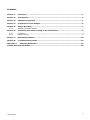
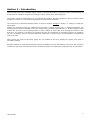
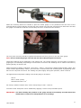
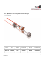
Arc Weldable Vibrating Wire Strain Gauge User Manual Man 175 6.0.2 06/08/14 Lucie Williams Phil Day Chris Rasmussen Manual No. Revision Date Originator Checked Authorised for Issue User Manual 1 Contents Section 1 : Foreword ....................................................................................................... 3 Section 2 : Introduction .................................................................................................. 4 Section 3 : Equipment Supplied ...................................................................................... 5 Section 4 : Preparation of the Gauges ............................................................................. 6 Section 5 : Gauge Mounting ............................................................................................ 7 5.01 Section 6 : 6.01 6.02 Setting the Strain Gauge ................................................................................... 7 Protection and Cable routing of the Installation ............................................ 9 Protection ....................................................................................................... 9 Cable Routing .................................................................................................. 9 Section 7 : Data Interpretation ..................................................................................... 10 Section 8 : Troubleshooting Guide ................................................................................ 13 Appendix A. Vibrating Wire Data ................................................................................. 14 Trouble Shooting Flowchart ............................................................................................ 15 User Manual 2 Section 1 : Foreword Soil Instruments Vibrating Wire Arc Weldable Strain Gauge, as with all our equipment, has been designed to operate consistently in a construction site environment and is, therefore, relatively robust. However, it is essential that the equipment covered by this manual is both operated and maintained by competent and suitably qualified personnel. They must READ AND UNDERSTAND the procedures outlined in this manual before attempting installation or operation of the equipment on site. Soil Instruments will not accept for repair under guarantee, instruments that have been neglected or mishandled in any way. User Manual 3 Section 2 : Introduction The Soil Instruments Arc Weldable Strain Gauge is intended primarily for long-term strain measurements on structural steel members such as tunnel linings, arches, struts, piles, sheet piling etc. The primary means of attachment is by conventional arc welding, but they can also be used to measure strain changes on concrete or rock surfaces using anchors grouted into boreholes. The nature of the instrument dictates that it is used to measure changes in strain (i.e. change in length per unit length). Strains are measured using the vibrating wire principle: a length of steel wire is tensioned between two mounting blocks that are welded to the steel surface being studied. Deformations (i.e. Strain changes) of the surface will cause the two mounting blocks to move relative to each other, thus altering the tension in the steel wire. The tension is measured by plucking the wire and measuring its resonant frequency of vibration. The wire is plucked, and its resonant frequency measured, by means of an electromagnetic coil positioned next to the wire. Note: Ensure the ends of the strain gauge are not rotated as this may damage the gauge and result in unreliable readings. Portable readouts or fixed data acquisition systems available from Soil Instruments will provide the necessary excitation to pluck the wire and convert the measured frequency to display the reading directly in microstrain. User Manual 4 Section 3 : Equipment Supplied For each installation you should have been supplied with: Two mounting blocks including gauge securing screws Sensor unit (gauge) securing clamp Each gauge is supplied with a pickup coil fitted with a user specified length of cable. The cable can be spliced to other cables for routing to a terminal location. Cables can be routed over distances in excess of 1000 metres without degradation of signal. Together with these a setting bar should be used to accurately locate the mounting blocks for welding; such bars are available from Soil Instruments. Although gauges are checked prior to leaving Soil Instruments, damage can occur during transit. It is suggested that the gauges are visually checked immediately upon receipt. Additionally it is prudent to check the operation using a vibrating wire readout device to ensure steady readings, if an audio signal is available on the readout device this can give a good indication of the quality of the signal. Before installation, a note should be made of the batch factors for the Strain Gauges for future data interpretation. Securing Screw Mounting Block Sensor (Gauge) Pick up Coil Tensioning Screws User Manual 5 Section 4 : Preparation of the Gauges Where a number of gauges are to be installed on a structural element it is essential that each gauge and its associated cables are accurately and effectively identified. A permanent marking system should be adopted to ensure gauges can be identified throughout their working lifetime and this information safely stored for future reference. Check the resistance between the two lead wires. It should be around 150 ohms. If the gauge contains a thermistor, check its resistance. Check the reading against that which should be obtained at the existing ambient temperature. Any faulty units should be returned to the factory. Gauges should not be opened in the field. The choice of gauge installation location is a critical factor in the design of an instrumentation scheme. Prior to installation of the gauges it is essential to plan the cable routing from the gauge location to the terminal position. The cables should be marked and where possible, extended before the gauge is installed. Two approaches to cable routing are commonly adopted, each with their own merits. (a) Each gauge sensor coil is factory fitted with a length of cable to reach from the gauge location to the terminal. This removes the need for jointing cables on site in, often, unsatisfactory conditions. It is, however, the slightly more expensive option and involves the handling and tying of, often, long lengths of cable. (b) The gauge sensor coils are factory fitted with a short (say 3m) length of cable and the cable from each gauge in an array is routed to a high quality cable joint where it is connected to a multicore cable. The multicore cable is then routed to the terminal location. With the cable routing planned and the gauges marked with their appropriate location description, mounting the gauges can begin. User Manual 6 Section 5 : Gauge Mounting The Soil Instruments Arc Weldable Strain Gauge is attached to mounting blocks, which must first be arc welded to the steel surface to be studied. A setting bar is used to correctly space apart the two blocks. Firstly the two mounting blocks are fitted over the ends of the setting bar and the jig is used to position them correctly. Then the set screws in the mounting blocks are tightened down onto the setting bar. Avoid excessive tightening as this only damages the setting bar unduly. The steel surface is cleaned using a wire brush to remove all scale, rust, dirt and oil. The blocks are then removed from the spacing jig and pressed firmly against the steel surface using the setting bar as a handle. The edges of the mounting blocks are now welded. Avoid excessive heat and do not weld the flat end surfaces as this will prevent removal of the setting bar. To speed things up, where many gauges are being installed it is advantageous to have more than one setting bar. After welding, cool the mounting blocks with a water soaked rag, then slacken the screws and slide out the setting bar. Clean away all welding slag using a chipping hammer and wire brush. 5.01 Setting the Strain Gauge Clip the plucking coil over the gauge, secure with the securing clamp as shown below and connect it to the readout box. User Manual 7 When the mounting blocks are welded in place the strain gauge is now positioned into the holes of the mounting blocks, ensure that the grooved end of the gauge lies inside the mounting block without the slot and the gauge is orientated so that the coil and clamp are not in contact with the structure. The cone point set screw should be tightened hard down into the V groove in one end of the gauge. Note: Do not rotate the gauge once the end has been clamped by the set screw. Check that readings can be displayed by the readout unit. The reading frequency can be made to increase by gripping the coil assembly and pushing in the direction of the free end. Readings can be made to decrease by pushing directly on the free end. When the desired reading is obtained, (mid range = 2500, compressive readings approximately 3500 and tensile strains approximately 1500.) the free end is secured inside the mounting block by tightening down hard on the oval point set screws. The reading may alter slightly during this operation, which is normal. The approximate mid position reading of the strain gauge is as follows: 910 Hz 830 F²/1000 (Linear) 10976 Period units x 107 For sweep excitation readout units, set the sweep range to 400 – 1200 Hz Corrosion at the weld points can be inhibited by applying a coat of rust preventative paint. IMPORTANT The final reading and position of the gauge should be accurately recorded since this detail will be required for interpretation of its readings. User Manual 8 Section 6 : Protection and Cable routing of the Installation 6.01 Protection All efforts must be taken to protect the gauge during and after installation. An insulated protective cover is available to protect the gauge from physical damage and the temperature effects of direct sunlight. This can be either welded over the gauge installation or secured with threaded fixings. Where the gauge is installed in a vulnerable position good practice is to spray the area with marker paint as a warning. 6.02 Cable Routing Having established and marked the preferred route of the cables and decided upon the type of cabling arrangement to be adopted, begin running the cables from the gauges furthest from the readout location. Where cables are not to be ducted, they should be strapped in a position where they are least likely to be damaged, using strong tape or cable ties. Cable should be supported every 400-500mm and care should be taken to avoid over stretching the cables, especially where movement/loading could take place. Where significant movement could take place, the cable ties should be left a little slack and sufficient cable left free and positioned so that it cannot be damaged. Once the cables have been fixed a full set of readings should be recorded for each instrument. Since the gauges are used to record changes in data and not absolute data, the stage when the "Base" or "Zero" reading is recorded is flexible. Where loading tests are to be performed, the Base reading for the test data should be recorded just prior to the beginning of the test. Data from Vibrating Wire instruments can be recorded in 3 formats; Period, Linear or Engineering Units. The required format should be established prior to any test beginning and remain consistent for the duration of the monitoring program. A monitoring schedule should be established by the engineers responsible for the structure, so that the monitoring personnel are aware of the data gathering requirements. User Manual 9 Section 7 : Data Interpretation Data from strain gauges is generally presented in micro strain (με) where strain is the ratio of the change in length per unit length:Practical K factor = 36150 (Gauge calibration constant) Conversion of Period and Linear Units to micro-strain is carried out using either of the formulae detailed below:Period Units Where = Change in strain in micro-strain = Gauge Calibration Constant = Base reading in Period units x 107 = Current reading in Period units x 107 = Batch Factor supplied with each gauge Please note: when is positive the resultant strain is tensile. Linear Units = Where = Change in micro-strain = Gauge Calibration Constant = Base reading in = Current reading in units units = Batch Factor supplied with each gauge Please note: when is positive the resultant strain is tensile. The calculation of Load in a member using data from strain gauges is often complex. The fundamental problem is determining the composite Young Modulus (E) of the member, since it is often difficult to accurately determine the properties of the insitu materials. User Manual 10 Once a Young Modulus is calculated, the following equations can be used to calculate the loading on the structural member at the location of the Strain Gauge. Force (F) = Stress (S) x Area (A) Where A = Cross sectional area in m² Where F units = Newton’s Where S units = N/m² Stress (S) = Young Modulus of Elasticity (E) x Strain ( ) Where E units = N/m² Example calculation Steel pipe outside diameter = 1.016m Steel pipe inside diameter = 0.984m Calculated change from the strain gauges = 54.688 Young Modulus of Elasticity of the steel pipe = 200,000,000,000 N/m² Stress = E x = 200,000,000,000 x 0.000054688 =10937600 N/m² Area = r² = x (outside diameter /2)² - = x (1.016 /2)² - = x (0.508)² - = x 0.258064 - x (inside diameter /2)² x (0.984 /2)² x (0.492)² x 0.242064 = 0.810732 m² – 0.760466 m² = 0.050266 m² Force = S x A = 10937600 x 0.050266 = 549789.4N User Manual 11 Section 8 : Temperature Correction It is best practice to record temperature when you record strain readings. You can then use the temperature data as well as strain data to analyse the behaviour of the structure. The steel used for the wire in the strain gauge has a thermal coefficient of expansion similar to that of structural steel. Thus, if the gauge and the steel have the same thermal coefficient of expansion and are subjected to the same temperature change, corrections for temperature change are not required. If the gauge is heated by direct sunlight, so that its temperature increases faster than that of the structural steel, you may see large changes in apparent strain. It is difficult to correct for this, so try to shield gauges from direct sunlight using thermally insulated covers. If the steel in the structure has a thermal coefficient that is quite different from that of the gauge, the following temperature correction might be appropriate. corrected = (TCm TCg ) x(Temp1 Temp0 ) Where: is the change in strain, TCm is the thermal coefficient of the member TC g is the thermal coefficient of the gauge:12.2 /°C Temp1 is the current temperature Temp0 is the initial temperature User Manual 12 Section 9 : Troubleshooting Guide If a failure of any vibrating wire transducer or its electrical cable is suspected, the following steps can be followed. The transducers themselves are sealed and cannot be opened for inspection. The “Troubleshooting Flowchart” should also be followed if any instrument failures are suspected. The steps below and the Troubleshooting Flowchart are applicable generally to any vibrating wire instrument. Step 1 Before any of the following steps are followed, the readout unit should be used to verify the stability of the reading and the audio signal from the portable logger should be heard. The period reading from the transducer should not vary by more than 2 units and the audio signal should be crisp and of a consistent tone and duration. Unstable (wildly fluctuating) readings from a transducer or an unsteady audio signal are either indications of possible problems with instruments or their related electrical cables. IMPORTANT: If a portable data logger is giving faulty readings or audio signals from all transducers, a faulty readout unit must be suspected. Another readout unit should be used to check the readings from the transducers and Soil Instruments should be consulted about the faulty readout unit. Before proceeding to Steps 2 and 3, if possible the continuity should be checked between conductors and earthing screen of the electrical cable. If continuity exists, a damaged cable is confirmed. Step 2 The resistance across the two conductors of the electrical cable should be checked. This can be done using a multimeter device across the two exposed conductors if the cable has not been connected to a terminal cabinet, or can be done just as easily across the two conductors if the instrument has been connected to such a terminal (or Dataloggers). The resistance across the two conductors should be approximately of the order of 80 to 180. The majority of these resistances arise from the transducer and the remainder from the electrical cable connected to the transducer. Step 3 If the resistance across the two conductors is much higher than the values quoted in “Step 2” (or is infinite), a damaged cable must be suspected. Step 4 If the resistance across the two conductors is much lower than the values quoted in “Step 1” (say 80 or less) it is likely that cable damage has occurred causing a short in the circuit Step 5 If the resistance is within the values quoted in “Step 1” (i.e. 80 to 180), AND no continuity exists between conductor and earth screen and on checking the reading from the transducer, it proves to be still unstable or wildly fluctuating, it must be assumed that the integrity of the circuit is good. A faulty transducer must be suspected and Soil Instruments should be consulted. NOTE: If the location on site of cable damage is found, the cable can be spliced in accordance with recommended procedure with suitably qualified personnel. Bell Lane, Uckfield, East Sussex t: +44 (0) 1825 765044 e: [email protected] TN22 1QL United Kingdom f: +44 (0) 1825 744398 w: www.itmsoil.com Soil Instruments Ltd. Registered in England. Number: 07960087. Registered Office: 5th Floor, 24 Old Bond Street, London, W1S 4AW User Manual 13 Appendix A: Vibrating Wire Data Frequency Units (f): The tension of a wire can be measured by registering the frequency (note) at which it naturally vibrates. If the wire is "plucked" electronically the frequency at which it vibrates can be measured. The most common units used to express frequency are Hertz (Hz) or KiloHertz(KHz). The disadvantage of these units is that there is no "linear" conversion from Hertz to "change in wire tension". Linear Units (L): In order to overcome the problem of a linear conversion described above, the frequency value can be squared, thereby rendering it linear, but quite large. To reduce its size it is often divided by 1000 (or multiplied by 10-3). The expression f2/1000 (or f2 x 10-3) is the most commonly adopted as a "linear" digital output. Period Units (P): Electronic devices and digital technology often utilise the "counter" function available in some common circuits. Period Units represent the time taken for the wire to vibrate over one full oscillation, expressed in seconds. Due to the very small size of the number generated most equipment manufacturers display the unit multiplied by 10000000 (or 10-7). The relationship between Period Units and frequency units is expressed as P1 frequency Period units are, therefore, convenient to measure but do not have a linear relationship to "change in wire tension". Calibration Constants: Each instrument is supplied with a Calibration Constant value, to convert the raw data into engineering units. The value of the calibration constant will vary depending upon the engineering units into which the data is to be converted and the readout units. For example, the data from piezometers may convert into Kg/cm2, mH20, Bar, Psi, etc, and, therefore, the Calibration Constant for each will be different. Some instruments have "Generic" Calibration Constants and others are calibrated to generate the Constant. The constant is generated by using the following calculation. Constant (K) = Range Reading @ Full Range - Reading @ Range Zero x 10-4 User Manual 14 Appendix B: Trouble Shooting Flowchart Is reading from portable logger stable, sensible and audio signal steady? Yes There is no reason to suspect a faulty instrument Yes A damaged cable or damaged cable joint are suspected No Does a continuity exist between earthing screen and conductor? No Check magnitude of resistance (R) between conductors. R is very high R < 80 Ohm R is between 80 & 180 Ohm A severed cable is suspected causing very high or infinite resistance. It must be suspected that the portable logger used first is faulty. Contact Soil Instruments Ltd. User Manual A faulty readout is suspected. Check reading of instrument with another unit. Yes Is reading OK with alternative logger? A damaged cable is suspected causing a short. (See step 4) No A faulty instrument is possible. Contact Soil Instruments Ltd. 15 User Manual 16