1
SRS10 (SRS11 / SRS13 / SRS14) Series
Digital Controller
Instruction Manual
Thank you for purchasing a Shimaden Digital Controller. After making sure the product fits the desired description,
you should carefully read the instructions and get a good understanding of the contents before attempting to operate
the equipment.
Request
The instruction manual should be kept in a handy place where the end user can refer to it when necessary.
Preface
The instruction manual was written for those who perform wiring, installation and routine maintenance for the
SRS10 (SRS11/SRS13/SRS14) Series. The instruction manual contains a description of the operating method,
functions, wiring, mounting method and precautions when handling the SRS10 (SRS11/SRS13/SRS14) Series
(hereinafter referred to as the SRS10 Series unless a separate description is required). You should therefore keep it
in a handy place to refer to when operating and handling the equipment. Be sure to observe all precautions and
adhere to the procedures provided in the manual. The intsruction manual assumes that fixed value control is applied.
For information on programming function and communication (optional items), see the instruction manual for the
individual function.
SRS10F-1BE
Sep. 2008
Contents
Request.......................................................................1
6. Screen explanation and setting items.................16
Preface........................................................................1
7. Measuring range codes .......................................23
1. Safety rules.............................................................3
8. Explanation of functions .....................................24
2. Introduction...........................................................3
8-1. Events ..................................................................... 24
2-1. Preliminary check......................................................3
(1) Alarm action ................................................................... 24
(2) Event standby action selection........................................ 24
(3) Event selection alarm action diagrams ........................... 24
(4) Event status output action............................................... 24
(1) Model code check..............................................................4
(2) Accessories check..............................................................4
2-2. Notes on use ..............................................................4
8-2. P.I.D. ...................................................................... 25
3. Installation and wiring..........................................4
(1) P (Proportional action).................................................... 25
(2) I (Integral time) .............................................................. 25
(3) D (Derivative time)......................................................... 25
(4) MR (Manual reset) ......................................................... 25
3-1. Installation site (environmental conditions) ..............4
3-2. Mounting ...................................................................5
3-3. External dimensions and panel cutout.......................5
3-4. Wiring .......................................................................6
3-5. Terminal layout .........................................................6
3-6. Terminal arrangement table.......................................7
3-7. Operation preparations ..............................................7
8-3. Control output ........................................................ 25
(1) Lower limit and higher limit setting limiter.................... 25
(2) Proportional cycling time ............................................... 26
(3) Control output characteristics ......................................... 26
8-4. External control input (DI) ..................................... 26
(1) Controller action execution EXE1 (RUN1) .................... 26
(2) Controller action execution EXE2 (RUN2) .................... 26
(3) Manual output (MAN).................................................... 26
(4) Auto tuning execution (AT) ............................................ 26
(5) SV external selection (ESV2) ......................................... 27
(6) Program (PROG) ............................................................ 27
(7) Hold signal (HLD).......................................................... 27
(8) Advance (ADV).............................................................. 27
(9) Start pattern external selection 2 bits (PTN2) ................. 27
(10) Start pattern external selection 3 bits (PTN3) ............... 27
(11) Total unlatching (L_RS) ............................................... 27
4. Names and functions of parts on front panel......8
5. Parameter diagram and setting ...........................9
5-1. Parameter diagram.....................................................9
5-2. Display when power is applied ...............................11
5-3. Switching screens....................................................11
(1) Switching screens within screen group 0 ......................11
(2) Switching between screen group 0 and screen group 1 ...11
(3) Switching screens within screen group 1.........................11
(4) Switching to screen group 2 ............................................12
(5) Switching screens within screen group 2.........................12
(6) Switching to screen group 3 ............................................12
(7) Switching to screen group 4 ............................................12
(8) Switching screens within screen group 4.........................12
(9) Set data modification.......................................................12
8-9. Soft start ................................................................. 27
(1) Conditions that trigger soft start ..................................... 27
(2) Conditions that cancel soft start...................................... 28
9. Causes and remedy of trouble and errors.........28
9-1. Causes and remedy of trouble ................................ 28
9-2. Causes and remedy of errors .................................. 28
5-4. Auto return function ................................................13
5-5. Screen group 0 setting .............................................13
(1) Abnormal measured input............................................... 28
(2) Heater break/loop alarm errors ....................................... 28
(1) Setting target set values (SV) ..........................................13
(2) Manual setting of control output......................................13
(3) Auto tuning (AT) .............................................................14
(4) Standby (STBY) / execution (EXE) ................................15
(5) Event setting....................................................................15
(6) Multi SV (target set values).............................................15
10. Parameter setting record ..................................29
11. Specifications .....................................................31
2
1. Safety rules
Safety rules, precautions concerning equipment damage, additional instructions and notes are written based on the following headings.
WARNING: Matters that could result in injury or death if instructions are not followed.
CAUTION: Matters that could result in equipment damage if instructions are not followed.
NOTE: Additional instructions or notes.
WARNING
The SRS10 Series digital controllers are designed to control temperature, humidity and other physical amounts for general industrial
equipment.
You should either take appropriate safety measures or avoid using for control that could have a serious effect on human life.
The manufacturer shall not be liable for an accident that results if used without taking appropriate safety measures.
● The digital controller should be used so the terminal elements in the control box, etc., are not touched by humans.
● Do not remove the controller from its case, or insert your fingers or electric conductors inside the case.
Doing so could result in electric shock or accident involving death or serious injury.
CAUTION
If there is danger of damage to any peripheral device or equipment due to failure of the controller,
you should take appropriate safety measures such as mounting a fuse or overheating prevention device.
The manufacturer shall not be liable for an accident that results if used without taking appropriate safety measures.
● Controller labels and alert mark
Alert marks are printed on the terminal label of the case.
You could be shocked if you touch charged parts. The alert marks are provided to call your attention to this.
● Provide a switch or breaker as a means of cutting off power for external power circuit connected to the power terminal of
the controller.
Mount a switch or breaker near the controller where the operator can get to it easily and label it as an electrical breaker for
the controller.
Use a switch or breaker that conforms to requirements of IEC60947.
● Fuses
The controller does not have a built-in fuse. Be sure to mount a fuse on the power circuit connected to the power terminal.
Provide a fuse between the switch or breaker and the controller. Mount on the L side of the power terminal.
Fuse rating/characteristics: 250V AC, 0.5A/medium time-lagged type or time-lagged type
Use a fuse that conforms to requirements of IEC60127.
● Voltage/current of load connected to the output terminal and EV terminal should be within the rating.
Using voltage/current that exceeds the rating could shorten the life of the contoller by raising the temperature, and could
result in equipment failure. For rating, see “11. Specifications.”
Connect equipment that conforms to requirements for IEC61010 to the output terminal.
● Do not apply voltage/current other than rated input to the input terminal.
Doing so could shorten product life and lead to equipment failure.
For rating, see “11. Specifications.”
If the input is voltage or current, connect equipment that conforms to IEC61010 to the input terminal.
There are draft holes in the controller for heat to escape from. Do not allow foreign matter such as metal to get into the holes.
Doing so could result in equipment failure or fire.
● Do not allow the draft holes to become clogged with dust, etc.
Doing so could shorten the life of the product due to temperature rise or insulation deterioration, and could result in equipment
failure or fire.
For space between instruments, see “3-3. External dimensions and panel cutout.”
● Repeating endurance tests such as dielectric strength, noise resistance and surge resistance could negatively affect the controller.
● The user should absolutely not modify or use the controller other than the way it was intended.
2. Introduction
2-1. Preliminary check
The controller has undergone sufficient quality control inspections, but you should check the specification code/appearance and
make sure you have all the accessories to make sure nothing is missing or damaged.
Compare the specification code on the case with the following to make sure it is the product you ordered.
The SRS10 Series offers a selection of two codes: SRS11 and SRS13/14.
3
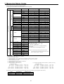
(1) Model code check
(SRS11 model code)
SRS11-8 Y Y-90-P 1 1 1 0
1. Series
2. Input
3. Control output 1
4. Control output 2
EV3/DI4
5. Power supply
6. Programming function
7. Event output
8. Analog output/communication
10. Remarks
SRS11
8: Multi-input, thermocouple, R.T.D., voltage (mV) 6: Voltage (V)
Y: Contact I: Current P: SSR drive voltage V: Voltage
N: None Y: Contact I: Current P: SSR drive voltage V: Voltage
E: Event output 1 point (EV3) D: External control input 1 point (DI4)
90: 100-240V AC
08: 24V AC/DC
N: None P: With (4 patterns, max. 32 steps)
0: None 1: Event output 2 points (EV1, EV2)
0: None 3: Voltage (0 ~ 10 mV) 4: Current (4 ~ 20 mA)
6: Voltage (0 ~ 10 V)
5: communication (RS-485)
0: None 1: CT 2 points input (Can be selected if control output 1 or 2 is Y, P)
2: External control input 3 points
0: None 9: With
1. Series
2. Input
3. Control output 1
4. Control output 2
EV3/DI4
5. Power supply
6. Programming function
7. Event output
8. Analog output
9. CT input
10. External control input
11: Communication
12. Remarks
SRS13 or SRS14
8: Multi-input, thermocouple, R.T.D., voltage (mV) 6: Voltage (V)
Y: Contact I: Current P: SSR drive voltage V: Voltage
N: None Y: Contact I: Current P: SSR drive voltage V: Voltage
E: Event output 1 point (EV3) D: External control input 1 point (DI4)
90: 100-240V AC
08: 24V AC/DC
N: None P: With (4 patterns, max. 32 steps)
0: None 1: Event output 2 points (EV1, EV2)
0: None 3: Voltage (0 ~ 10 mV) 4: Current (4 ~ 20 mA) 6: Voltage (0 ~ 10 V)
0: None 1: CT input 2 points (Can be selected if control output 1 or 2 is Y, P)
0: None 2: Control input 3 points (DI1, DI2, DI3)
0: None 5: RS-485
0: None 9: With
9. DI/CT input
(SRS13/SRS14 model code)
SRS13-8 Y Y-90-P 1 4 1 2 5 0
(2) Accessories check
Instruction manual
Communication interface instruction manual (if communication optional item added)
Programming function instruction manual (if programming function optional item added)
Unit seals
1 copy
1 copy
1 copy
1 sheet
Note: Receiving impedance for current input (250Ω, 0.1%), current detector for heater break alarm (CT) and terminal cover
are sold separately as optional items and are not included with the controller.
Note: In the event you want to inquire about a product defect, missing accessory or other matter, please contact your
nearest Shimaden agent.
2-2. Notes on use
Do not press front panel keys with a hard or pointed object. Press lightly with your fingertips.
To clean, wipe lightly with a dry cloth. Do not use solvents such as thinner.
3. Installation and wiring
3-1. Installation site (environmental conditions)
CAUTION
Environmental conditions for operations
The controller is designed to be used under the following
conditions. Observe the following environmental
conditions when using:
c Must be used indoors
d Max. elevation: 2000m
e Ambient temperature: -10 to 50°C
f Ambient humidity: Max. 90%RH, no condensation
g Transient over voltage category: II
h Pollution class: 2 (IEC 60664)
Do not use the controller in the following locations.
Doing so could lead to equipment failure, damage or fire.
* Places exposed to flammable or corrosive gases, oil mist, or
excessive dust that could cause insulation to deteriorate.
* Places subject to vibration or impact
* Places near strong electric circuit or places subject to inductive interference
* Places exposed to water dripping or direct sunlight
* Places where the controller is struck directly by air from heater or air
conditioner
4
3-2. Mounting
CAUTION
In order to maintain safety and function, do not remove the case from the controller.
If the case of the controller has to be removed for replacement/repair, contact your nearest Shimaden agent.
c
d
e
f
g
Cut a hole for mounting the controller in the panel by referring to external dimentions and panel cutout in section 3-3.
The panel thickness should be 1.0 – 3.5 mm.
The controller is provided with tabs for mounting. Insert as is from the front surface of the panel.
Controllers of the SRS10 Series are designed for mounting on the panel. Be sure to mount on the panel.
If mounted in series, provide ventilation so ambient temperature does not exceed 50°C due to temparature rise caused by heat
generation.
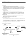
3-3. External dimensions and panel cutout
Panel cutout
SRS11
(48×N-3) +1.0
-0
45 +0.6
-0
Min. 60
45 +0.6
-0
45 +0.6
-0
If mounted horizontally
N=Number of units
Unit: mm
SRS13
Panel cutout
92 +0.8
-0
Min. 130
92 -0
+0.8
Min. 130
Unit: mm
SRS14
Panel cutout
(48×N-3)+1.0
-0
Min. 130
92 -0
92 -0
+0.8
+0.8
45 +0.6
-0
If mounted horizontally
N=Number of units
Unit: mm
External dimensions of current detector for heater break alarm (CT)
0 ~ 30A (CTL-6-S)
0 ~ 50A (CTL-12-S36-8)
2.36
40
3
10.5
25
5.8
21
15
10
12
30
40
2- 3.5
7.5
2-M3
30
40
5
Unit: mm
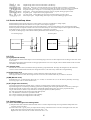
3-4 Wiring
CAUTION
● Be sure to turn off power before wiring. Failure to do so could result in electric shock.
● After wiring, do not touch terminal elements or other charged parts while conducting electricity. Failure to do
so could result in electric shock.
Take the following precautions when wiring:
c Wire in accordance with the terminal layout of section 3-5 and the terminal arrangement table of section 3-6. After wiring,
check and make sure the wiring is correct.
Crimp-type terminals fit M3 screws. Use crimp-type terminals that are no wider than 6 mm.
For thermocouple input, use a compensating conductor that matches the type of thermocouple.
For R.T.D. input, resistance for lead wires should be a maximum of 5Ω per wire. All 3 wires should have the same resistance.
Input signal wires must not be accommodated with a strong electric circuit in the same conduit or duct.
Using shielded wiring (single point grounding) is effective for static induction noise.
Making input wiring short and twisting at regular intervals is effective for electromagnetic induction noise.
For power supply, use wiring or cable with sectional area of at least 1 mm² that offers the same performance as 600V vinyl
insulated wiring.
k Securely fasten the terminal element screw. Fastening torque: 0.5 N·m (5kgf·cm)
l If the instrument appears to be easily affected by power supply noise, use a noise filter to prevent malfunctioning.
Mount the noise filter on the grounded panel and make the wire connection between the noise filter output and power line
terminals of the controller as short as possible.
d
e
f
g
h
i
j
Make this wire short.
Noise filter
100~
240V AC
Recommended noise filter:
DENSEI-LAMBDA MAW-1202-22
IN
OUT
Controller
100~
240V AC
50/60Hz
Ground
Current transformer (CT) connection method (CT input optional)
To CT input terminal of
controller (no polarity)
Heater (load) wire
Pass one of the load lines through the dedicated CT hole.
Wire from the CT secondary side terminal to the CT input terminal
of the SRS10 Series.
There are 2 combinations of CT connection terminals for the
SRS10 Series, which can detect current for 2 heater combinations.
CT
3-5. Terminal layout
Wire in accordance with the following terminal layout and terminal arrangement table.
SRS11
SRS13/SRS14
6
3-6. Terminal arrangement table
Name of terminal
Power supply
Description/code
Analog output
(optional)
100-240V AC/24V AC:L,24V DC:+
100-240V AC/24V AC:N,24V DC: –
R.T.D: A, thermocouple / voltage /
current: +
R.T.D: B, thermocouple / voltage /
current: –
R.T.D: B
Contact: NO, SSR drive voltage /
voltage / current: +
Contact: NO, SSR drive voltage /
voltage / current: –
Contact: NO, SSR drive voltage /
voltage / current: +
Contact: NO, SSR drive voltage /
voltage / current: –
COM
EV1
EV2
EV3
CT1 input
CT2 input
COM
DI1
DI2
DI3
DI4
+
–
Communication
(optional)
RS-485: +
RS-485: –
Input
Control output 1
Control output 2
(optional)
Event output
(optional)
CT input (optional)
External control
input / DI
(optional)
Terminal No.
SRS11 SRS13/14 Note1: With thermocouple / voltage / current input,
shorting across B and B terminal will cause
7
13
an error.
8
14
4
22
Note2: The following optional function of the SRS10
Series are limited to exclusive selection.
5
23
6
9
24
15
10
16
11
17
12
18
1
2
3
11-12
13-14
15-16
13
14
15
16
11-12
17
18
19
20
21
17-18
7-8
9-10
1
2
3
4
17-18
5
6
17
18
11
12
SRS11: Only one among control output 2, event
output 3 and external control input DI4 can
be selected.
Either CT input or external control input
DI1 – 3 can be selected.
Either analog output or communication can
be selected.
SRS13: Only one among control output 2, event
SRS14 output 3 and external control input DI4 can
be selected.
3-7. Operation preparations
Before operating the controller, you should first check the wiring and carry out the following by screen group setting method.
There is however no need to change the settings that have been set at the factory or already been made by the manufacturer.
1.
Wiring check
Make sure the wiring to the connection terminals is correct. Incorrect wiring could result in burnout.
2.
Power ON
Turn on the operating power. The displays, etc., light when power is supplied to the controller.
3.
Measuring range setting
Select code from Measuring Range Codes of “4-57 Measuring range codes setting screen” of 1 screen group and enter.
Select temperature unit of “4-58 Input unit setting screen” of 1 screen group and enter.
For current, voltage and mV input, set lower limit value, higher limit value and position of decimal point of display contents
for input signal.
(You should also select by 4-59, 4-60 and 4-61 screens by code.)
4.
Control mode (PID) setting
For ON-OFF (2 position) action, select OFF by “2-1. Output 1 PID1 proportional band setting screen” of 2 screen group and enter.
Sets hysteresis by “2-2. Output 1 PID1 hysteresis setting screen.”
If equipped with output 2, set by same method.
If using auto tuning (AT) with other than ON-OFF hysteresis, this setting operation is not required.
5.
Control output characteristics setting
Select RA (for heating) or DA (for cooling) according to output specification (heating/cooling) on “4-45 Output 1 output
characteristics setting screen” and “4-48 Output 2 output characteristics setting screen” of 4 screen group and enter.
6.
Event type setting
If equipped with event, select types of event on “4-2, 4-7 and 4-12 Event type setting screen” of 4 screen group and enter.
7.
Analog output setting
If equipped with analog output, select items to be output as analog signals on “4-23 Analog output type setting screen” of 4
screen group and enter.
8.
Precaution concerning initialization by data modification
Modifying measuring range code, type of event or type of analog output initializes related setting values (data). The data
must therefore be set again.
7
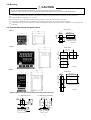
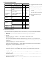
4. Names and functions of parts on front panel
c Measured value (PV) display
d Target set value (SV) display
e Action display
f Operating keys
Name
c Measured value (PV)
display
d Target set value (SV)
display
e Action display
f Operating keys
Function
(1) Measured value display LED (red)
* Displays current PV value on basic screen (screen 0-0).
* Displays type of parameter on each respective parameter display screen.
(2) Target value display LED (green)
* Displays current PV value on basic screen (screen 0-0).
* Displays setting values on each respective parameter setting screen.
Displays status of controller.
* RUN: Action display LED (green)
Off: Standby or reset
On: Running by fixed value control
Flashing: Running by program
* AT : Auto tuning LED (green)
Off: Auto tuning not executed
On: Auto tuning standby
Flashing: Auto tuning being executed
* MAN: Manual control LED (green)
Off: Output by automatic control.
Flashing: Output by manual control.
* OUT1: Control output 1 (green)
* OUT2: Control output 2 (green)
For output by contact or SSR drive voltage:
Off: Output is OFF.
On: Output is ON.
For voltage/current output:
Brightness changes according to the output ratio.
(Light brightly if output is 100% and dimly if output is 0%.)
* EV1: Event output 1 (orange)
* EV2: Event output 2 (orange)
* EV3: Event output 3 (orange)
Off: Event output is OFF.
On: Event output is ON.
Note: Always off if event output is not selected as an optional item.
* COM: Communications mode (green)
Off: Communications local mode
On: Communications COM mode
*
: Parameter key
Displays the next screen in various screen groups
Pressing and holding for at least 3 seconds on 0-0 screen displays 4-0 initial settings screen group.
*
: Down key
Decrements setting values.
*
: Up key
Increments setting values.
* ENT : Enter key
Enters setting values.
Displays various screen groups if no SV values are being modified on the basic screen.
* RUNRST : RUN/RST key
Pressing and holding for at least 2 seconds in STBY (RST) status switches to EXE (RUN).
Pressing and holding for at least 2 seconds during EXE (RUN) switches to STBY (RST).
status.
Fixed value control (FIX mode) STBY: Standby status EXE: Control execution status
Program control (PROG mode) RST: Reset status
RUN: Program execution status
8
5. Parameter diagram and setting
5-1 Parameter diagram
The overview of the parameter diagram is as follows. The windows of the various screens are divided as follows. The number at
the top left of the window is the screen No.
Screen always displayed by key operation, etc.
Screen displayed when concerned optional item is added
Screen to be shown or hidden according to the setting
Programming function / communication function related screens
Screens explained by respective function instruction manuals
No monitor screen (3 minutes auto return)
0 screen group
1 screen group
2 screen group
0-0
0-1
0-2
Monitoring OUT1
0-3
Monitoring OUT2
0-4
Monitoring program
execution step No.
0-5
Monitoring remaining
time of program step
0-6
Monitoring number
of program patterns
0-7
Monitoring program
execution PID No.
0-8
Program hold
execution setting
0-9
Program advance
execution setting
0-10
Monitoring
heater current 1
0-11
Monitoring
heater current 2
0-12
0-13
0-14
0-15
0-16
EV1 setting
EV2 setting
EV3 setting
AT execution
Monitoring program
start pattern
0-17
Latching release
0-0 Basic screen
1-1
FIX initial
screen
FIX ON/OFF
1-2
SV No. setting
1-3
1-4
1-5
Initial screen
1-0
SV1 setting
value
SV2 setting
value
SV3 setting
value
1-0 Initial screen
PID1 screen group
2-0
2-1
PID1 initial
screen
2-3
OUT1
hysteresis
OUT1 integral
time
2-4
OUT1 derivative
time
2-5
2-6
2-7
2-8
OUT1 MR
OUT1 SF
OUT1 lower
limit limiter
OUT1 higher
limit limiter
2-9
OUT2
proportional band
2-10
2-11
OUT2
hysteresis
OUT2 integral
time
2-12
OUT2 derivative
time
2-13
2-14
2-15
2-16
OUT2 dead
band (DB)
OUT2 SF
OUT2 lower
limit limiter
OUT1 higher
limit limiter
PID2 screen group
OUT1
proportional band
2-2
2-0 Initial screen
9
2
sec.
2-0
2-1
2
sec.
3-0
PID3 screen group
Initial screen
2-0
2-1
Program screen
group
2-2
2-2
See programming
function instruction
manual
Initial setting
screen group
See following
page
2-3
2-3
2-4
2-4
2-5
2-5
2-6
2-6
2-7
2-7
2-8
2-8
2-9
2-9
2-10
2-10
2-11
2-11
2-12
2-12
2-13
2-13
2-14
2-14
2-15
2-15
2-16
2-16
4 screen group
4-0
3 seconds
Basic screen
Standby setting
3 screen group
2-0 Initial screen
2-0 Initial screen
Note 1. All screens of the 0 screen
group switch to next screen
when the key is pressed.
Note 2. All screens of 1, 2 and 4 screen
groups switch to next screen when
the key is pressed and return
immediately to the preceding
screen when the RUN/RST
key is pressed.
Note 3. For switching among the 0 screen
group, 1 screen group, 2 screen
group and 3 screen
group, pressing the key switches
to the initial screen of the next
screen group.
Note 4. Besides the initial screen of the 2
screen group, pressing and holding
the key for at least 2 seconds
switches to the initial screen of the
next PID No. in the 2 screen group.
Note 5. To switch between the 0 screen
group and 4 screen group, pressing
and holding the key for at least
3 seconds in the 0-0 basic screen
of the 0 screen group or 4-0 initial
screen of the 4 screen group,
switches to the other screen group.
0-0 Basic screen
3 seconds
4 screen group
4-0
4-21
4-1
4-2
4-3
Initial screen
Key lock setting
EV1 mode setting
EV1 hysteresis setting
4-4
4-5
4-6
EV1 standby action
setting
EV1 latching setting
EV1 output
characteristics setting
4-7
4-8
EV2 mode setting
EV2 hysteresis setting
4-9
4-10
4-11
EV2 standby action
setting
EV2 latching setting
EV2 output
characteristics setting
4-12
4-13
EV3 mode setting
EV3 hysteresis setting
4-14
4-15
4-16
EV3 standby action
setting
EV3 latching setting
EV3 output
characteristics setting
4-17
4-18
4-19
4-20
Heater 1 alarm mode
setting
Heater 1 break alarm
setting
Heater 1 loop alarm
setting
Heater 2 alarm mode
setting
4-21 screen
Heater 2 burnout alarm
setting
4-22
4-23
Heater 2 loop alarm
setting
Analog output type
setting
4-24
4-25
Analog output scaling
lower limit value setting
Analog output scaling
higher limit value setting
4-26
4-27
4-28
4-29
4-30
4-31
4-32
Analog output limiter
lower limit setting
Analog output limiter
higher limit setting
DI1 mode setting
DI2 mode setting
DI3 mode setting
DI4 mode setting
Communication mode
setting
4-33
4-34
4-35
4-36
4-37
Communication
address setting
Communication data
format setting
Communication start
character setting
Communication BCC
check setting
Communication speed
setting
4-38
4-39
Communication delay
time setting
Communication
memory mode setting
4-40
Communication master
mode setting
4-41
Communication master mode
start slave address setting
4-42 screen
10
4-42
Communication master mode
finish slave address setting
4-43
Communication master mode
write data address setting
4-44
Output 1 proportional
cycling time setting
4-45
4-46
Output 1 characteristics
setting
Output 1 soft start time
setting
4-47
Output 2 proportional
cycling time setting
4-48
4-49
Output 2 characteristics
setting
Output 2 soft start time
setting
4-50
4-51
4-52
4-53
4-54
SV limiter lower limit
value setting
SV limiter higher limit
value setting
Number of program
patterns setting
Program time unit
setting
PV bias value setting
4-55
4-56
PV gain compensation
value setting
4-57
4-58
PV filter time setting
Measuring Range
Codes setting
Temperature unit
setting
4-59
4-60
Input scaling lower limit
value setting
4-61
Input scaling higher
limit value setting
Input decimal point
setting
4-0 Initial screen
5-2. Display when power is applied
When power is applied, the initial screen when power is applied displays each screen for about 1 sec. and switches to the basic
screen of screen group 0 as shown in the following figure.
Series name (, , )
Input type (: thermocouple, : R.T.D., : Voltage [mV], : Voltage [V])
(For current mA input, select voltage input after providing receiving impedance of 250Ω externally.)
Indicates control output 1
OUT1 output type (: Contact, : SSR drive voltage, : Voltage, :Current)
Indicates control output 2
OUT2 output type (, , , )
Lower limit value of selected measuring range
Higher limit value of selected measuring range
0-0 basic screen, 0 screen group from here
Measured value (PV): Switches to screen for setting various functions by operation key from “0-0 basic screen.”
Target set value (SV): For screen sequence, see parameter diagram on previous page.
5-3. Switching screens
Within 0 screen: Screen group primarily set by end users.
Screen group 1: Target set value setting screen group (multi SV).
Screen group 2: Screen group that sets PID constant.
Screen group 3: Displayed if equipped with programming function (optional). See “Programming Function Instructions.”
Screen group 4: Screen group primarily set by manufacturer / equipment maker. (Initial setting screen group)
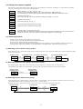
(1) Switching screens within screen group 0
Each time the key is pressed the screen display switches to the next screen. If pressed when the last screen is displayed, returns
to the 0-0 basic screen.
0-0 Basic screen
0-1 Standby screen
0-2 Output 1 monitoring
0-17 Latching release screen
(2) Switching between screen group 0 and screen group 1
Pressing the key on the basic screen of screen group 0 switches to “1-0 initial screen” of screen group 1.
Pressing the key on the “1-0 initial screen” of screen group 1 switches to the initial screen of screen group 2.
Screen group 0
0-0 Basic screen
Screen group 1
1-0 Initial screen
key
(3) Switching screens within screen group 1
Each time the key is pressed on the “1-0 initial screen” in screen group 1, the screen display switches to the next screen. If
pressed when the last screen is displayed, returns to the “1-0 initial screen.”
With screen group 1, each time the key is pressed, the screen is switched in the reverse direction.
1-0 Initial screen
1-1 FIX on/oFF
1-5 FIX SV3
11
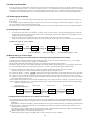
(4) Switching to screen group 2
Pressing the key on the “1-0 initial screen” switches to the “2-0 initial screen” of screen group 2.
Screen group 1
0-0 Basic screen
Screen group 2
2-0 Initial screen
(5) Switching screens within screen group 2
The “2-0 initial screen” in screen group 2 is the PID1 setting initial screen. Each time the key is pressed, the setting initial
screen switches PID2→PID3→PID1. Pressing the key switches PID1→PID3→PID2.
Screen group 2
2-0 PID1 initial screen
PID2 initial screen
PID3 initial screen
Each time the key is pressed the screen display switches from the various initial screens to the next screen. If pressed when
the last screen is displayed, returns to the “2-0 initial screen.”
With screen group 2, each time the key is pressed, the screen is switched in the reverse direction.
2-0 PID1 initial screen
2-1 screen
2-2 screen
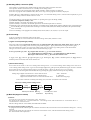
(6) Switching to screen group 3
Screen group 3 is the program screen group. It is not displayed unless it is set as an optional item.
Pressing the key on the “2-0 initial screen” switches to the “3-0 initial screen” of screen group 3.
Further pressing the key switches to the basic screen.
Screen group 2
2-0 PID setting screen
Screen group 3
3-0 Initial screen
For more information on the programming function, see the “Programming Function Instructions.”
(7) Switching to screen group 4
Screen group 4 is the initial setting screen group. Various settings are made prior to using the controller.
Pressing the key on the basic screen of screen group 0 for at least 3 seconds switches to “4-0 initial screen” of screen group 4.
Pressing the key on the “4-0 initial screen” of screen group 4 for at least 3 seconds switches to the basic screen of screen group 0.
Screen group 0
0-0 Basic screen
key
At least 3 seconds
Screen group 4
4-0 Initial screen
(8) Switching screens within screen group 4
Each time the key is pressed screen display switches from the initial screens to the next screen. If pressed when the last
screen is displayed, returns to the “4-0 initial screen.”
With screen group 4, each time the key is pressed, the screen is switched in the reverse direction.
4-0 Initial screen
4-1 screen
4-2 screen
(9) Set data modification
Data is modified on the various screens by pressing the or key. The modified data is entered by pressing the key.
12
5-4. Auto return function
If no key operation is conducted for 3 minutes on the various screens (with the exception of the “0-2 output 1 monitoring screen”,
“0-3 output 2 monitoring screen”, “0-4 step No. monitoring screen”, “0-5 remaining time of step monitoring screen”, “0-6 number
of pattern execution monitoring screen”, “0-7 Execution PID No. monitoring screen”, “0-10 heater current 1 monitoring screen” or
“0-11 heater current 2 monitoring screen”), the mode automatically returns to the “0-0 basic screen” of screen group 0 (auto return).
5-5. Screen group 0 setting
The flow is given in “6. Screen description and setting items.” This section however primarily contains a description of how to
make settings.
As for the key operation method, the key switches to the next screen. The settings are selected with the key or key on
the various setting screens and entered with the key.
Pressing the key is however not required for modifying output values on the output monitoring screen for manual adjustment.
(1) Setting target set values (SV)
1.
2.
To set target set values (SV), press the key or key on the “0-0 basic screen.” Pressing and holding the key causes the
decimal point of the lowest digit to flash, and the value is incremented or decremented. When the desired target set value is
reached, enter by pressing the key.
When the setting is entered, the decimal point of the lowest digit of the target set value stops flashing.
Target values cannot be set while auto tuning (AT) is being executed. To set target values, you must first cancel auto tuning.
Example: Set target set value to 500.0°C.
0-0 Basic screen
key
Then press
key
and
Decimal point flashes
Decimal point flashes
key
Decimal point stops flashing
Enter
(2) Manual setting of control output
1) Output monitoring screen (OUT1/OUT2) and switching and setting automatic/manual output
To toggle between automatic and manual, press and hold the key on the “0-2 output 1 monitoring screen” or “0-3 output 2
monitoring screen” or press the key and keys simultaneously.
During manual output, the MAN lamp flashes and it goes off during the automatic output operation.
Pressing the key or key on the output monitoring screen during manual output enables you to set the manual output values.
To return to automatic output, press and hold the key for 3 seconds or press the and keys simultaneously.
c Changing output action of either output 1 or output 2 to manual automatically changes the other to manual.
Similarly, changing one to auto also automatically changes the other to automatic as well.
If output of output 1 is 100.0%, is displayed on the output 1 monitoring screen and the decimal point of flashes.
If output of output 2 is 100.0%, is displayed on the output 2 monitoring screen and the decimal point of flashes.
If output is contact or SSR drive voltage and the proportional band (P) setting is OFF, the output value is 0.0% or 100.0%.
If output is voltage or current and the proportional band (P) setting is OFF, the output value is the lower limit value or higher
limit value of the output limiter set.
NOTE1: Manual output cannot be changed while automatic tuning (AT) is being executed. To change, you must first cancel AT.
NOTE2: If MAN is selected in “4-28 – 4-31 DI mode setting screen”, external control input has a priority and manual output change
cannot be conducted in 0-1 screen.
d
e
f
g
Automatic output
0-1 Output monitoring screen
Manual output
key 3 seconds
MAN lamp off
+ keys
Manual output
key
Automatic output
key 3 seconds
and key
+ keys
MAN lamp flashing
MAN lamp flashing
MAN lamp off
2) Supplementary explanation for use of manual control output
The correlation of the “0-2 output 1 monitoring screen” and “0-3 output 2 monitoring screen” and automatic/manual output is as follows:
c Output when automatic output is changed to manual is balanceless bumpless action, and the output value prior to change value is
displayed.
When manual is changed to automatic, it becomes bumpless action except if measured value (PV) is outside the proportional band.
d If power supply is cut off and turned back on, control output action continues in automatic or manual mode, whichever was set
when the power was shut off.
Note: You can switch to another screen in the manual mode as well, but you should note that control output is also manual mode.
When the MAN monitor LED is flashing, the controller is in manual mode.
e Manual output (MAN) is canceled in the following cases:
When range, input unit, input scaling higher limit or input scaling lower limit is modified.
13
(3) Auto tuning (AT)
Function that automatically processes and sets parameter PID for PID control. Processing time varies according to control.
1) AT execution
Pressing the key on the “0-15 AT action control screen” causes the display at the bottom to change to and the
decimal point of the smallest digit to flash.
Pressing the key then executes AT. The decimal point stops flashing and the AT lamp flashes.
When AT is executed, ON/OFF hysteresis of output is repeated several times according to increment or decrement of measured
values. The PID value is saved in the internal memory and the action ends. Control based on the PID value in the memory
simultaneously starts and the AT lamp stops flashing.
0-15 AT action control screen
key
key
Decimal point flashes
Decimal point stops flashing
AT lamp flashes
AT execution
2) Cancellation of AT
To cancel AT before it finishes, select with the key on the “0-15 AT action control screen.” When the key is
pressed, AT is cancelled. The decimal point and the AT lamp then stop flashing.
0-15 AT action control screen
key
Decimal point stops flashing
AT lamp flashes
AT execution
key
Decimal point flashes
AT lamp flashes
Decimal point stops flashing
AT lamp stops flashing
AT canceled
Note: If AT is canceled before completeion, PID value is not changed.
3) AT cannot be executed
AT cannot be executed under any of the following conditions:
c Control output is manual. (AT screen not displayed)
d Standby (AT screen not displayed)
e Measured value (PV) is scaleover. (AT screen not displayed)
f Control output 1 proportional band (P) is OFF. (AT screen not displayed)
g If lock No. 2 or 3 is set on the key lock screen.
4) AT cancellation during execution
AT is canceled during execution under any of the following conditions:
c If 200 continuous minutes elapse while output value is 0% or 100%.
d When PV is scaleover.
e When switched to standby action.
5) AT action for 2-output specifications
With 2-output specifications, AT action changes according to RA/DA characteristics as follows:
c When OUT1/2 characteristics differ (RA/DA or DA/RA)
PID constant is same value for both output 1 and output 2.
d RA characteristics for both OUT1/OUT2 or DA characteristics for both OUT1/OUT2
AT action is executed for output 1 only; OUT2 during AT execution is 0% output or output limiter lower limit value.
NOTE: During AT execution, any setting change cannot be conducted except for cancellation of AT, change to standby mode, key
rock setting and change of transmission mode.
14
(4) Standby (STBY) / execution (EXE)
The controller is equipped with a standby mode for temporarily halting controller execution.
This operation mode is switched on the “0-1 standby action setting screen.”
In the case of fixed value control (FIX mode), STBY (standby) / EXE (execution) is displayed.
In the case of program control (PROG mode), RST (reset: stop) / RUN (program execution) is displayed.
If EXE1 (RUN1) or EXE2 (RUN2) is selected on the “4-28 – 4-31 DI mode setting screen”, external control input (DI) is given
priority and settings cannot be made on the 0-3 screen.
c The RUN lamp is lit green while the controller is operating and it goes off during standby.
d Controller output for standby is 0%.
e When standby is executed, auto tuning (AT) is canceled.
f When standby is executed in the manual input mode, the manual input mode is canceled.
g When the power is turned off while the controller is in standby mode, standby mode continues when the power is turned back on.
h If event standby action is specified when switching to execution mode (EXE) from standby mode (StbY), the specified standby
action is executed.
i If event latching is not engaged in the standby mode, alarms (Hd, Ld, od, id, HA, LA) are not output.
(5) Event setting
Types of event must be set before setting event values.
Modifying the types of event code however initializes setting values (data) related to events.
1) Types of event (alarm type) setting
Select type code from among Hd, Ld, od, id, HA, LA, So, EXE(run), HC1, HC2, StPS, PtnS, EndS, hoLd, ProG, u_SL, d_SL
on the “4-2 event 1 type setting screen of screen” group 4 with the key / key and enter the event type with the key.
Set event 2 and event 3 on the “4-7 event 2 type setting screen” and “4-12 event 3 type setting screen” in the same manner.
The types of event for which event values can be set are the following 6 types:
Event type (alarm type) code: : higher limit deviation, : lower limit deviation,
: outside higher/lower limit deviation, : inside higher/lower limit deviation,
: higher limit absolute value, : lower limit absolute value
If : none, : scaleover, : EXE signal (: RUN signal), : heater 1 break/loop alarm, or : heater 2
break/loop alarm is selected, event values cannot be set.
2) Event values setting
Event values are set on the “0-12 event 1 setting values setting screen”, “0-13 event 2 setting values setting screen” and “0-14
event 3 setting values setting screen.” Type of event is displayed when one of the previously mentioned 6 types of events is selected.
Event values are set by selecting setting range by pressing the key / key on the 0-12, 0-13 or 0-14 screen.
When the event value setting has been decided, enter by pressing the key and the decimal point stops flashing.
Setting range: Higher limit deviation or lower limit deviation
Outside or inside higher/lower limit deviation
Higher limit absolute value or lower limit absolute value
-1999 – 2000 unit
0 – 2000 unit
Within measuring range
Event values cannot be set during auto tuning (AT) execution. AT must first be canceled.
0-5 event 1 setting values setting screen
key
Then
Decimal point flashes
key
During
modification
Decimal point Enter
stops flashing
(6) Multi SV (target set values)
1) Multi SV
You can set 3 types of target set values (SV). (SV1, SV2, SV3)
SV values are set on the “1-3 – 1-5 FIX control SV1 – SV3 setting screen” and execution SV No. is selected on the “1-2
execution SV No. selection screen.”
PID No. during multi SV is SV1/PID1, SV2/PID2 and SV3/PID3.
2) External selection switching of multi SV
If equipped with external control input DI, if ESV2 is allocated to DI, execution SV can be selected from among SV1 – SV3 by
DI input.
Using 2 points of DI, DI to be used for SV selection is allocated on “4-28, 4-29 DI1 and DI2 mode setting screen.”
See “8-4. External control input (DI) .”
15
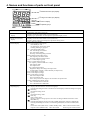
6. Screen explanation and setting items
0-0
basic screen
4-0 Initial screen
3 seconds
Initial values: 0 or measuring range lower limit values
Setting range: Within measuring range (within SV limiter)
Measured value (PV) is displayed at the top and target set value
(SV) is displayed/modified on the bottom.
For details, see 5-5 (1).
0-1
1-0 Initial screen
Initial value: EXE ()
Setting range: StbY (), EXE
0-0
Basic Screen
Displays measured value (PV) at the top; on the bottom the
output 1 control output value is monitored when in automatic
mode and setting is modified when in manual mode.
Manual output setting range: 0.0 – 100.0 (%)
0-10
Heater current 1 monitoring screen
FIX event values setting
FIX event is an event of fixed value control (FIX mode).
Program control event values are set by the program screen group.
Displays measured value (PV) at the top; on the bottom the
output 2 control output value is monitored when in automatic
mode and setting is modified when in manual mode.
Manual output setting range: 0.0 – 100.0 (%)
Displayed if optionally equipped with output 2.
For details, see 5-5 (2).
0-12
FIX event 1 (EV1) setting value setting screen
Execution step No. monitoring screen
Event No. and type of event are displayed on the top.
Initial value:
Higher limit deviation value: 2000 (unit)
Lower limit deviation value: -1999 (unit)
Outside or inside higher/lower limit deviation: 2000 (unit)
Higher limit absolute value: Measuring range higher limit value
Lower limit absolute value: Measuring range lower limit value
Setting range:
Higher limit deviation value or lower limit deviation value: -1999 – 2000 (unit)
Outside or inside higher/lower limit deviation: 0 – 2000 (unit)
Higher limit absolute value or lower limit absolute value: Within measuring range
If equipped with event option, displayed when EV1 alarm code
Hd – LA are assigned, and action point of allocated alarm type
is set. For details, see 5-5 (5).
Displays execution step No. for program operation.
Remaining time of step monitoring screen
:
current value of heater current 2 (CT2).
The following 0-4~0-6, 0-8~0-9, 0-16 screens are screens for
optional programming function.
The screens are not displayed if not equipped with the
programming function.
Displayed if optionally equipped with heater break/loop alarm;
displays current value of heater 1 (CT1).
(No setting item)
Because this is a monitoring screen, auto return does not function.
--- : Displayed when stable current value could not be read.
0-11
Heater current 2 monitoring screen
Just as with the heater current 1 monitoring screen, displays
Output 2 (OUT2) monitoring screen
You can execute advance during program operation.
If ON is selected, the step currently being executed is completed
and the program forcibly jumps to the next step.
*Output monitoring screens (OUT1/OUT2) and
automatic/manual output
●You can toggle between automatic and manual by pressing
and holding the key for at least 3 seconds on the output 1
or output 2 screen, or you can press the and keys
simultaneously.
●When either the output 1 or output 2 mode is changed (to automatic
or manual), the other changes automatically.
●The MAN lamp flashes during manual output.
For details, see 5-5 (2).
You can turn hold ON/OFF during program operation.
The program is temporarily halted by hold ON.
0-9
Advance execution setting screen
Output 1 (OUT1) monitoring screen
0-5
0-4
0-8
Hold execution setting screen
Display only if the “4-28 – 4-31 DI mode setting screen” is set to
EXE1 or EXE2.
StbY (standby): Action stop, EXE: Selects execution action.
For program operation, rSt (/reset), run (/run)
setting.
For standby action, see 5- 5 (4).
0-3
3-0 screen
Standby action setting screen
0-2
2-0 screen
0-13
FIX event 2 (EV2) setting value setting screen
Displays remaining time of program for program operation.
Same as 0-12 screen above except EV2 instead of EV1.
0-6
Number of pattern executions monitoring screen
0-14
FIX event 3 (EV3) setting value setting screen
Displays remaining number of patterns executed for program
operation.
0-7
Execution PID No. monitoring screen
Same as 0-12 screen above except EV3 instead of EV1.
Can be set if E (event output1 point, EV3) is selected for output2
of type code.
To 0-15 screen
Displays PID No. being executed for program operation.
16
0-15
Auto tuning (AT) action control screen
1-5
Target set values SV3 setting screen
Initial value: oFF
Setting range: oFF, on
AT is executed by on selection and is canceled by oFF selection.
This screen is not displayed for manual output or for output 1
proportional band (P) OFF setting.
Not displayed if STANDBY is set for 0-1 standby action setting
screen. During AT execution, key operation other than AT cancel,
key lock setting and communication mode is not accepted.
For AT action, see 5- 5 (3).
To 1-0 screen
PID setting
0-16
Start pattern No. monitoring screen
Display screen for program operation.
Same as 1-3 screen above except SV3 instead of SV1.
Sets target set values used by fixed value control.
PID setting screen group
With the SRS10 Series, you can have 3 types of PID constants.
In the case of fixed value control (FIX), target set values SV1, SV2 and SV3
correspond to PID1, PID2 and PID3 respectively.
In the case of program control, an execution PID No is allocated to each step.
Initial value: 1
Setting range: 1, 2, 3, 4
Differs according to number of patterns (max. 1, 2, 4)
Displays/sets starting pattern No.
1-0
0-17
Unlatching screen
FIX setting initial screen
Initial value: rSt1
Setting range: rSt1, rSt2, rSt3, ALL
Note: Displayed only when event latching is selected.
Pressing the key on the 1-0 screen switches to the PID1
setting screen.
2-0
PID setting screen
PID1
If event latching is ON, even if event conditions no longer exist
after event action, the event continues to be output. (Event selfhold)
Cancels self-hold of the event.
PID2
2-1 screen
If latching can be canceled, the decimal point for the lowest digit
on the concerned setting screen flashes. Pressing the key
cancels the concerned event.
FIX control (fixed value control) setting
control.
FIX setting initial screen
Note:Set PID2 and PID3 on the 2-0 – 2-16 screens just
as with PID1.
Displayed by pressing the key on the basic screen.
Fixed value for no programming function.
Set to multi SV fixed value control in using multiple target set
values.
2-1
Output 1 PID1 proportional band (P) setting screen
1-1
FIX control ON/OFF switching screen
Can be switched to fixed value control if equipped with
programming function.
Initial value: on
Setting range: on, oFF
On: fixed value control, oFF: Program control
2-2
Initial value: 20 (unit)
Setting range: 1 – 999 (unit)
Sets “hysteresis” for ON–OFF action.
Displayed if P = oFF is set on 2-1 screen.
2-3
Output 1 PID1 integral time (I) setting screen
1-3
Target set values SV1 setting screen
Output 1 PID1 hysteresis (dF) setting screen
Displays execution SV No. used by fixed value control.
Initial value: 1
Setting range: 1 – 3
Initial value: 3.0 (%)
Setting range: oFF, 0.1 – 999.9 (%)
There is basically no need to set if auto tuning (AT) is executed.
For information on proportional band, see 8-3 (1). If oFF is set,
ON-OFF (2 position) action is set.
1-2
Execution SV No. setting screen
Sets target set values used by fixed value control.
Initial value: 0
Setting range: Within SV limiter range
Initial value: 120 (seconds)
Setting range: oFF, 1 – 6000 (seconds)
There is basically no need to set if auto tuning (AT) is executed.
For information on integral time, see 8-3 (2).
This screen is not displayed when P = OFF.
1-4
Target set values SV2 setting screen
2-1 screen
There are no setting items for this screen. Pressing the key
displays the initial output 1 PID1 proportional band (P) setting
screen.
Pressing the key displays the last output 2 higher limit setting
screen.
0-0 Basic screen
Setting related to multi SV (target set values) for fixed value
The numbers at the end of the upper display are PID No.s that
correspond to SV1, SV2 and SV3 respectively.
Pressing the key displays the screen in the order of
PID1→PID2→PID3→PID1.
Pressing the key displays the screen in the order of
PID1→PID3→PID2→PID1.
Pressing the key on these screens switches to screen group 3
(equipped with programming function) or the basic screen.
To 0-0 Basic screen
1-0
PID1
Setting and corresponding event No:
rSt1:EV1, rSt2:EV2, rSt3:EV3,
ALL:EV1, EV2, EV3
PID3
To 2-4 screen
Same as 1-3 screen above except SV2 instead of SV1.
Sets target set values used by fixed value control.
To 1-5 screen
17
2-4
Output 1 PID1 derivative time (D) setting screen
Initial value: 30 (seconds)
Setting range: oFF, 1 – 3600 (seconds)
2-13
Output 2 dead band (DB) setting screen
There is basically no need to set if auto tuning (AT) is executed.
This screen is not displayed when P = oFF.
To 2-5 screen
2-6
2-14
Output 2 PID 1 target set value function setting screen
Initial value: 0.0%; 2- output specification: -50.0 (%)
Setting range: -50.0 – 50.0 (%)
2-15
Output 2 PID1 lower limit output limiter setting screen
2-7
2-16
Initial value: 100.0 (%)
Setting range: (2oL1 setting value) + 0.1 – 100.0 (%)
Sets control output 2 higher limit value.
To 2-0 screen
Initial value: 0.0 (%)
Setting range: 0.0 – 99.9 (%)
Output 2 PID1 higher limit output limiter setting screen
Output 1 PID1 lower limit output limiter setting screen
Sets control output 2 lower limit value.
Used for suppressing overshoot and undershoot for expert PID.
Overshoot for SF = 1.00 is minimal. With SF = oFF, there is
ordinary PID action without expert PID. This screen is not
displayed when P = oFF.
Initial value: 0.0 (%)
Setting range: 0.0 – 99.9 (%)
Initial value: 0.40
Setting range: oFF, 0.01 – 1.00
Same as output 1 target set value function setting screen.
This screen is not displayed when P = oFF.
Output 1 PID1 target set value function (SF) setting screen
Initial value: 0.40
Setting range: oFF, 0.01 – 1.00
Offset is conducted when I = oFF. (P/PD action)
This screen is not displayed when P = oFF.
See 8-3 (4).
Sets action position of output 2 for target set values.
For information on dead band, see section 8-4 (3).
2-5
Output 1 PID1 manual reset (MR) setting screen
Initial value: 0 (unit)
Setting range: -1999 – 5000 (unit)
Sets control output 1 lower limit value.
For information on output limiter, see 8-4 (1).
Initial settings screen
Initial settings screen group (screen group 4)
Output 1 PID1 higher limit output limiter setting screen
2-8
Initial value: 100.0 (%)
Setting range: (1oL1 setting value) + 0.1 – 100.0 (%)
Sets control output 1 higher limit value.
0-0 Basic screen
Pressing and holding the key for at least 3 seconds on the
0-0 basic screen displays the 4-0 initial screen.
3 seconds
4-0
2-9
Output 2 PID1 proportional band (P) setting screen
Initial value: 3.0 (%)
Setting range: oFF, 0.1 – 999.9 (%)
4-1
Output 2 PID1 hysteresis (dF) setting screen
Key lock setting screen
Initial value: 20 (unit)
Setting range: 1 – 999 (unit)
Lock No. and locked range are as follows:
Lock No.
Locked range
oFF
Unlock (all data can be modified)
All data locked except screen group 0 and
1
communication mode
All data locked except SV and communication
2
mode
3
Only key lock setting can be modified
2-11
Output 2 PID1 integral time (I) setting screen
Initial value: 120 (seconds)
Setting range: oFF, 1 – 6000 (seconds)
Same as output 1 integral time setting screen.
This screen is not displayed when P = oFF.
2-12
Output 2 PID1 derivative time (D) setting screen
Initial value: oFF
Setting range: oFF, 1, 2, 3
Locks items you don’t want to be modified.
To unlock, select oFF.
Data cannot be changed for a locked screen.
Sets “hysteresis” for ON–OFF action.
Displayed if P = oFF is set on 2-9 screen.
There are no setting items with this screen. Pressing the key
displays the initial setting screen 4-1 key lock setting screen
and pressing the key displays the last screen 4-61 input decimal
setting screen.
Same as output 1 proportional band setting screen.
Displayed if optionally equipped with output 2.
2-10
Initial screen
Event settings
Initial value: 30 (seconds)
Setting range: OFF, 1 – 3600 (seconds)
4-2
Event 1 (EV1) type setting screen
Same as output 1 derivative time setting screen.
This screen is not displayed when P = oFF.
Initial value: Hd (higher limit deviation)
Setting range: non, Hd, Ld, od, id, HA, LA, So, EXE(run) ,
HC1, HC2, StPS, PtnS, EndS, hoLd, ProG,
u_SL, d_SL,
Selected types of event are set in accordance with the code
table on the next page.
To 2-13 screen
To 4-3 screen
18
4-2 – 4-13 is not displayed when event output is not selected.
Event type code (used by 4-7 and 4-12)
Code
Types of event
(non)
( Hd)
( Ld)
( od)
( id)
( HA)
( LA)
( So)
(EXE)
(run)
(HC1)
(HC2)
(StPS)
(PtnS)
(EndS)
(HoLd)
(ProG)
(u_SL)
(d_SL)
4-3
No selection
Higher limit deviation
Lower limit deviation
Outside higher/lower limit
deviation
Inside higher/lower limit
deviation
Higher limit absolute value
Lower limit absolute value
Scaleover
EXE signal (fixed value
control being executed)
RUN signal (program
being executed)
Heater 1 break/loop alarm
4-8
Event 2 action hysteresis setting screen
Remarks
EV1 initial values
EV2 initial values
Sets ON-OFF hysteresis of event 2 just like EV1.
Displayed when alarm type code is Hd, Ld, od, id, HA, LA,
HC1, or HC2.
4-9
Event 2 standby action code setting screen
For fixed value control only
For program control only
Sets type of standby action for event 2 from the standby action
code table of 4-4 just like EV1.
Displayed when alarm type code is Hd, Ld, od, id, HA, LA,
HC1, or HC2.
For HC1/HC2, only oFF or 1 can be selected.
4-10
Event 2 latching setting screen
Initial value: 20 (unit)
Setting range: 1 – 999 (unit)
4-11
Event 2 output characteristics setting screen
Initial value: oFF
Setting range: oFF, 1, 2, 3
Standby action code (used by 4-9 and 4-14)
Code
Description of standby action
No standby
When power is applied, STBY(RST) →EXE(RUN)
When power is applied, STBY(RST)→EXE(RUN),
SV modification
Control mode (no standby)
For HC1/HC2, only oFF or 1 can be selected.
Standby action only when power is applid.
4-5
4-13
Event 3 action hysteresis setting screen
Initial value: 20 (unit)
Setting range: 1 – 999 (unit)
Sets ON-OFF hysteresis of event 3 just like EV1 .
Displayed when alarm type code is Hd, Ld, od, id, HA, LA,
HC1, or HC2.
Initial value: oFF
Setting range: oFF, on
oFF: Latching function unabled
on: Latching function enabled
4-14
Event 3 standby action code setting screen
With the event latching function, the event continues to be
output even if there are no event conditions after event action.
(Event self-hold)
Displayed when alarm type code is Hd, Ld, od, id, HA, LA, HC1,
HC2.
Initial value: oFF
Setting range: oFF, 1, 2, 3
Sets type of standby action for event 3 from the standby action
code table of 4-4 just like EV1.
Setting conditions are same as for EV1.
Event 1 output characteristics setting screen
Initial value: no
Setting range: no, nc
4-15
Event 3 latching setting screen
no: Normally open (output conductivity for event ON)
nc: Normally closed (output conductivity for event OFF)
4-16
Event 3 output characteristics setting screen
4-7
Event 2 (EV2) type setting screen
Initial value: oFF
Setting range: oFF, on
Set just like EV1.
Selects whether contact output for event action is conductive or
nonconductive.
Event output for power OFF is nonconductive for both no
and nc.
Initial value: EXE (run)
Setting range: non, Hd, Ld, od, id, HA, LA, So,
EXE(run) , HC1, HC2, StPS, PtnS, EndS,
hoLd, ProG, u_SL, d_SL,
Types of events selected for EV3 are set from the event type
code table of 4-2 just as with EV1.
4-12 – 4-16 screen is displayed if control output2 is selected as
event output (EV3).
Event 1 latching setting screen
4-6
Event 3 (EV3) type setting screen
4-12
Sets type of standby action for event 1 from code table.
Displayed when alarm type code is Hd, Ld, od, id, HA, LA,
HC1, or HC2.
Initial value: no
Setting range: no, nc
Set just like EV1.
4-4
Event 1 standby action code setting screen
Initial value: oFF
Setting range: oFF, on
Set just like EV1.
Sets ON-OFF hysteresis for event 1.
Displayed when alarm type code is Hd, Ld, od, id, HA, LA,
HC1, or HC2.
Initial value: oFF
Setting range: oFF, 1, 2, 3
Only when optionally
equipped
Heater 2 break/loop alarm Only when optionally
equipped
Step signal
For program control only
Pattern signal
For program control only
Program end signal
For program control only
Hold signal
For program control only
Program signal
For program control only
Up slope signal
For program control only
Down slope signal
For program control only
Event 1 action hysteresis setting screen
Initial value: 20 (unit)
Setting range: 1 – 999 (unit)
Initial value : Ld (lower limit deviation value)
Setting range: non, Hd, Ld, od, id, HA, LA, So, EXE (run),
HC1, HC2, StPS, PtnS, EndS,
HoLd, ProG, u_SL, d_SL,
Initial value: no
Setting range: no, nc
Set just like EV1.
To 4-17 screen
Types of events selected for EV2 are set from the event type
code table of 4-2 just as with EV1.
To 4-8 screen
19
Heater break/loop alarm settings
4-25
Can be used if event option and CT input option is eguipped.
Initial value: 800.0
(For PV/SV, measureing range higher limit value;
out1/out2 is 100.0)
Setting range: When PV or SV is selected, within measuring
range
When out1 or out2 is slected: 0.0 – 100.0 %
4-17
Heater 1 break/loop alarm mode setting screen
Analog output scaling higher limit value setting screen
Initial value: out1
Setting range: out1, out2
Maximum values of analog output signal (10mV, 20mA, 10V)
are set as scaling maximum value to be output.
Sets control output by which heater break/loop alarm is output
by current detection by CT1.
Can be set only for control output Y or P.
4-17 – 4-22 will be displayed if output of control output 1 or 2
is Y or P, and CT input is selected at the same time.
Inverse scaling is possible for Ao_L > Ao_H.
(Min. H-L=±1 count)
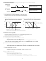
Characteristics by analog output scaling are as follows:
4-18
Heater 1 break alarm action value setting screen
For
Initial value: oFF
Setting range: oFF, 0.1 – 50.0 (A)
Sets current value of heater break alarm detected by CT1.
When control output is ON, an alarm is output if the current
value detected by CT1 is lower than the setting.
Analog output
100%
100%
0%
0%
0% Ao_L
Sets current value of heater loop alarm detected by CT1.
When control output is OFF, an alarm is output if the current
value detected by CT1 is higher than the setting.
4-27
Analog output limiter higher limit value setting screen
Initial value: oFF
Setting range: oFF, 0.1 – 50.0 (A)
Initial value: 100.0 (%)
Setting range: (AL_L setting value) + 0.1 – 100.0 (%)
Sets higher limit value of analog output.
External control input DI settings
Sets current value of heater break alarm detected by CT2.
When control output is ON, an alarm is output if the current
value detected by CT2 is lower than the setting.
4-28
DI1 mode setting screen
Initial value: non
Setting range: non, EXE1(run1), EXE2(run2), mAn, At, ESV2,
ProG, HLd, AdV, Ptn2, Ptn3, L_rS
4-22
Heater 2 loop break alarm action value setting screen
Initial value: oFF
Setting range: oFF, 0.1 – 50.0 (A)
Select/allocate/set according to usage objective of external
input (DI).
4-28 – 4-30 is not displayed if DI (external control input 3
points) is not selected.
Sets current value of heater loop alarm detected by CT2.
When control output is OFF, an alarm is output if the current
value detected by CT2 is higher than the setting.
DI mode allocation type code (used by 4-29, 4-30, 4-31)
Allocation
External control input
Code
possible Detection
allocation type
DI No.
No selection
EXE/STBY (FIX fixed value
1, 2, 3, 4
Level
() control)
RUN/RST (program control)
EXE/STBY (FIX fixed value
1, 2, 3, 4
Edge
() control)
RUN/RST (program control)
1, 2, 3, 4
Level
MAN: Manual output
1, 2, 3, 4
Edge
AT: Auto tuning execution
Level
ESV2: External selection 2bit 1, 2
1, 2, 3, 4
Level
ProG: Program
1, 2, 3, 4
Level
HLd: Hold signal
1, 2, 3, 4
Edge
AdV: Advance
1, 2
Level
Ptn2: Start pattern selection
2bit
1
Level
Ptn3: Start pattern selection
3bit
1, 2, 3, 4
Edge
L_rS: Total unlatching
Analog output settings
4-23
Analog output type setting screen
Initial value: PV ()
Setting range: PV, SV (), out1 (),
out2 ()
Item to be output as analog signal is set from among 4 items:
measured value (PV), target set values (SV), control output 1
(out1) and control output 2 (out2).
4-23 – 4-27 is not displayed if analogue output is not selected.
4-24
Analog output scaling lower limit value setting screen
Scaling range
Sets lower limit value of analog output.
4-21
Heater 2 break alarm action value setting screen
Ao_L 100%
Initial value: 0.0 (%)
Setting range: 0.0 – 99.9 (%)
Initial value: out1
Setting range: out1, out2
Sets control output by which heater break/loop alarm is output
by current detection by CT2.
Can be set only for control output Y or P.
0% Ao_H
4-26
Analog output limiter lower limit value setting screen
Ao_H 100%
Scaling range
4-20
Heater 2 break/loop alarm mode setting screen
Ao_L > Ao_H
Initial value: oFF
Setting range: oFF, 0.1 – 50.0 (A)
For
Analog output
4-19
Heater 1 loop break alarm action value setting screen
A o_L < Ao_H
Initial value: 0.0
(For PV/SV, measureing range lower limit value;
out1/out2 is 0.0)
Setting range: When PV or SV is selected, within measuring range
When out1 or out2 is slected: 0.0 – 100.0 (%)
Minimum values of analog output signal (0mV, 4mA, 0V) are
set as scaling minimum value to be output.
To 4-29 screen
To 4-25 screeen
20
If ESV2/Ptn2 is allocated to DI1, DI2 cannot be selected.
If Ptn3 is allocated to DI1, DI2 and DI3 cannot be selected.
A single type of code cannot be allocated to more than one DI.
4-29
BCC operation type
DI2 mode setting screen
Operation
Initial value: non
Setting range: non, EXE1(run1), EXE2(run2), mAn, At, ESV2,
ProG, HLd, AdV, Ptn2, L_rS
Set just like 4-28 DI1 mode.
If ESV2/Ptn2 is assigned to DI2, DI3 cannot be selected.
4-30
DI3 mode setting screen
4-37
Initial value: non
Setting range: non, EXE1(run1), EXE2(run2), mAn, At, ProG,
HLD, AdV, L_rS
4-31
DI4 mode setting screen
4-38
Communication delay time setting screen
Initial value: 20
Initial value: non
Setting range: non, EXE1(run1), EXE2(run2), mAn, At, ProG,
HLD, AdV, L_rS
Set just like 4-28 DI1 mode.
Displayed when DI4 is selected.
Displayed if D (external control input 1 point, DI4) is selected
for control output 2.
4-39
Communication memory mode setting screen
Communication settings
4-32
Communication mode setting screen
Initial value: Loc ( [local])
Setting range: Loc, Com ( [Com])
4-40
Communication master mode setting screen
4-40 – 4-43 screens are displayed only when master mode is
Can be changed from Com to Loc with the front surface key.
Communication is made possible by mode displayed on bottom.
4-33
Communication address setting screen
Initial value: 1
Setting range: mASt, 1 – 255
Sets device No. when multiple controllers are connected for
communication.
Setting to mASt sets the master mode.
4-34
Communication data format setting screen
Initial value: 7E1
Setting range: 7E1,7E2,7n1, 7n2,8E1,8E2, 8n1, 8n2
ASCII
RTU
Sets data format for communications.
Shima
Data
Parity Stop bit
den
length
{
Even
1 bit
7 bits
{
7 bits
Even
2 bits
{
7 bits
None
1 bit
{
7 bits
None
2 bits
{
8 bits
Even
1 bit
{
8 bits
Even
2 bits
{
8 bits
None
1 bit
{
8 bits
None
2 bits
4-41
4-36
Initial value: 1
Setting range: bcAS, 1 – 255
bcAs: Broadcast
4-42
Communication master mode end slave address
setting screen
Not displayed for bcAS (broadcast)
Initial value: 1
Setting range: Start address – start address + 30
4-43
Communication master mode write-in data address
setting screen
Initial values: StX ()
Setting range: StX, Att ()
Sets whether to use StX or Att (@) as the start characters of the
communications format.
Valid only for Shimaden protocol.
Initial value: 0300 (H)
Setting range: 0000 (H) – FFFF (H)
Setting in hexadecimal notation.
4-44
Output 1 proportional cycling time setting screen
Initial value: Contact output: 30 (seconds),
BCC operation type setting screen
selected on the 4-33 communication address setting screen.
Initial value: SV
Setting range: SV, out1, o1SC, out2, o2SC
Select data for transmission to slave when in master mode.
Displayed only when in master mode.
Type
Writing process
SV
Transmit execution SV value to slave.
OUT1 Transmit output percentage value of output1.
01SC Transmit measuring range value for output percentage of output1.
OUT2 Transmit output percentage value of output2.
02SC Transmit measuring range value for output percentage of output2.
Note1: “(measuring range x output percentage + lower limit
value of measuring range)” is the actual transmission data
when 01SC/02SC is selected.
Communication master mode start slave address
setting screen
MODBUS
ASCII
RTU
{
{
{
{
{
{
{
{
4-35
Start character setting screen
Initial value: EEP ()
Setting range: EEP, rAm (), r_E ()
Format for writing data in EEPROM and RAM during
communication is set from the following table.
Type
Writing process
Writing entirely in EEPROM
Writing entirely in RAM
Writing SV, OUT1 and OUT2 in RAM and others in EEPROM
For communication function, see the Communications
Interface Instruction Manual.
Setting range: 1 – 100
Sets delay time from when communication command is
received till transmission.
Delay time = Setting value × 0.512 msec
Initial value: 9600 (bps)
Setting range: 1200, 2400, 4800, 9600, 1920, 3840
Sets communication speed.
1200 - 9600:1200(bps) – 9600(bps),
1920:19200(bps), 3840:38400(bps)
Set just like 4-28 DI1 mode.
Communication speed setting screen
Description
None (Shimaden protocol)
Add operation (Shimaden protocol)
2’s complement after add operation (Shimaden protocol)
Exclusive OR (Shimaden protocol)
LRC (MODBUS ASCII)
CRC-16 (Modobus RTU)
Sets control output 1 proportional cycling time.
Not displayed when output type is voltage or current.
For information on proportional cycling time, see 8-3 (2).
Initial value: Add
Setting range: non, Add, Add2, Xor, Lrc, cr16
SSR drive voltage output: 3 (seconds)
Setting range: 1 – 120 (seconds)
4-45
Control output 1 characteristics setting screen
Process type of error detection BCC checking is set from
the following table.
To 4-37 screen
21
Initial value: rA ()
Setting range: rA, dA ()
Sets characteristics of control output.
rA: Reverse characteristics (for heating)
dA: Direct characteristics (for cooling)
For information on control output characteristics, see 8-3 (3).
To 4-46 screen
4-46
Control output 1 soft start time setting screen
4-54
PV bias value setting screen
Initial value: oFF
Setting range: oFF, 1 – 120 (seconds)
Sets soft start time that gradually changes output.
Does not function if oFF is set.
For details, see 8-6.
4-55
Initial value: Contact output: 30 (seconds),
SSR drive voltage output: 3 (seconds)
Setting range: 1 – 120 (seconds)
4-56
PV filter time setting screen
Initial value: rA ()
Setting range: rA, dA ()
Initial value: 0 (seconds)
Setting range: 0 – 9999 (seconds)
Used to alleviate the effect if input varies radically or
noise is superimposed.
Filter does not function if set to 0 seconds.
4-57
Measuring range code setting screen
4-49
Control output 2 soft start time setting screen
Used for compensating input gain error of sensors, etc.
When gain compensation is applied, control is also executed
according to the compensated value.
Sets characteristics of control output.
(RA) : Reverse characteristics (for heating)
(DA) : Direct characteristics (for cooling)
Displayed if Y, I, P, V is selected for control output 2.
Initial value: 0.00 (%)
Setting range: -5.00 – 5.00 (%)
4-48
Control output 2 characteristics setting screen
PV gain compensation value setting screen
Sets control output 2 proportional cycling time.
Not displayed when output type is voltage or current.
Used for compensating input error of sensors, etc.
When bias is applied, control is also executed according to the
compensated value.
4-47
Output 2 proportional cycling time setting screen
Initial value: 0 (unit)
Setting range: -1999 – 2000 (unit)
Initial value: Multi: 05, voltage: 86
Setting range: Selected from “Chapter 7: Measuring Range
Codes.”
Initial value: oFF
Setting range: oFF, 1 – 120 (seconds)
Combination of input type and measuring range is set by the code.
Setting cannot be changed during control action.
Sets soft start time that gradually changes output.
Does not function if oFF is set.
For details, see 8-6.
Displayed if Y, I, P, V is selected for control output 2.
Note: Setting cannot be changed during control action on
4-57 – 4-61 screen. Change setting with standby
mode on 0-1 screen.
If the setting is modified, all data related to measuring
range will be initialized.
4-50
SV limiter lower limit setting screen
Initial value: Lower limit value of measuring range
Setting range: Lower limit value of measuring range to higher
limit value of measuring range - 1 count
4-58
Input unit setting screen
If using setting range of target values below measuring range:
Set lower limit value.
(Able to prevent incorrect setting in danger range, etc.)
Initial value: c ()
Setting range: c, F ()
Temperature unit for sensor input is set to C (°C) or F (°F).
Not displayed if linear input (mV, V, mA) is selected.
K() is displayed if measuring range code is 15 – 18 (in kelvin).
Modification of unit is only possible when in standby mode.
4-51
SV limiter higher limit setting screen
Initial value: Higher limit value of measuring range
Setting range: Higher limit value of measuring range to lower
limit value of SV limiter + 1 count
4-59
Input scaling lower limit value setting screen
Initial value: 0.0 (unit)
Setting range: -1999 – 9989 (unit)
If using setting range of target values below measuring range:
Sets higher limit value.
(Able to prevent incorrect setting in danger range, etc.)
Sets scaling lower limit value for linear input (mV, V).
Cannot be set by monitoring screen for sensor input.
Note: For SV limiter setting, the lower limit value is given
preference when SV limiter lower limit value is less than
higher limit value. Consequently, higher limit cannot be
set less than lower limit value + 1 count.
4-60
Input scaling higher limit value setting screen
Initial value: 100.0
Setting range: (Sc_L setting value) + 10 – (Sc_L setting value)
+ 10,000
If Sc_L/Sc_H are changed, the respective values are set for
SV_L/SV_H.
Sets scaling higher limit value for linear input (mV, V).
Cannot be set by monitoring screen for sensor input.
4-52
Number of patterns setting screen
(programming function only)
Note: If the difference between the higher limit value and
lower limit value is less than +10 count or higher than
+10,000 count, the higher limit value is automatically
changed to + 10 count or +10,000 count. The higher
limit value cannot be set less than lower limit value +10
count or higher than +10,000 count.
Initial value: 4
Setting range: 1, 2, 4
Sets number of patterns used by programming function.
4-61
4-53
Time unit setting screen (programming function only)
Initial value: Hm ()
Setting range: Hm, mS ()
Input decimal point position setting screen
Sets time unit used by programming function.
Hm: Hour/minute, mS: Minute/second
To 4-54 screen
To 4-0 screen
22
Initial value: 1 digit following decimal point (0.0)
Setting range: No decimal point (0) – 3 digits following
decimal point (0.000)
Sets decimal point position for input scaling.
Cannot be set by monitoring screen for sensor input.
7. Measuring Range Codes
Select measuring range from the following table.
Changing the code initializes all data related to measuring range.
Kelvin
Universal-input
Thermocouple
Input type
B
R
S
Code
K
E
J
T
N
PLⅡ
WRe5-26
U
L
K
AuFe-Cr
K
AuFe-Cr
*3
*4
*5
*5
R.T.D
Pt100
V
Voltage
mV
JPt100
-10 ~ 10mV
0 ~ 10mV
0 ~ 20mV
0 ~ 50mV
10 ~ 50mV
0 ~ 100mV
-1 ~ 1V
0 ~ 1V
0 ~ 2V
0 ~ 5V
1 ~ 5V
0 ~10V
*1
*2
*2
*2
*6
*7
*6
*7
Measuring range (°C)
0
~ 1800 °C
0
~ 1700 °C
0
~ 1700 °C
-199.9 ~ 400.0 °C
0.0 ~ 800.0 °C
0
~ 1200 °C
0 ~
700 °C
0
~
600 °C
-199.9 ~ 200.0 °C
0
~ 1300 °C
0 ~ 1300 °C
0
~ 2300 °C
-199.9 ~ 200.0 °C
0
~
600 °C
10.0 ~ 350.0 K
0.0 ~ 350.0 K
~ 350 K
10
~ 350
K
0
-100.0 ~
350.0 °C
~
600 °C
-200
-100.0 ~ 100.0 °C
50.0 °C
- 50.0 ~
0.0 ~
200.0 °C
~
500 °C
-200
-100.0 ~
100.0 °C
50.0 °C
- 50.0 ~
0.0 ~
200.0 °C
-100.0 ~
350.0 °C
Measuring range (°F)
0
~ 3300 °F
0
~ 3100 °F
0
~ 3100 °F
-300
~ 750 °F
0
~ 1500 °F
0
~ 2200 °F
0
~ 1300 °F
0
~ 1100 °F
-300
~ 400 °F
0
~ 2300 °F
0
~ 2300 °F
0
~ 4200 °F
-300
~ 400 °F
0
~ 1100 °F
10.0 ~ 350.0 K
0.0 ~ 350.0 K
10
~
350 K
0
~
350 K
-150.0 ~ 650.0 °F
-300
~ 1100
°F
-150.0 ~ 200.0 °F
- 50.0 ~ 120.0 °F
0.0 ~ 400.0 °F
-300
~ 1000
°F
-150.0 ~ 200.0 °F
- 50.0 ~ 120.0 °F
0.0 ~ 400.0 °F
-150.0 ~ 650.0 °F
Initial value: 0.0 ~ 100.0
Input scaling setting range: -1999 ~ 9999
Span: 10 ~ 10,000 count
Decimal point position: None, 1/2/3 digits following
decimal point
Lower limit value is less than higher limit value.
NOTE: For current input, install input terminals of the
specified receiving impedance (250 Ω) and use code
84 (0 ~ 20 mA) or 85 (4 ~ 20 mA).
Thermocouple: B, R, S, K, E, J, T, N: JIS/IEC
R.T.D. Pt100: JIS/IEC JPt100
*1. Thermocouple B: Accuracy guarantee not applicable to 400°C (752°F) or below.
*2. Thermocouple K, T, U: Accuracy of those readings below -100°C is ±0.7% FS
*3. Thermocouple PLII: Platinel
*4. Thermocouple WRe5-26: A product of Hoskins
*5. Thermocouple U, L: DIN 43710
*6. Thermocouple K (Kelvin) accuracy
*7. Thermocouple Metal-chromel (AuFe-Cr) (Kelvin) accuracy
Temperature range
Temperature range
0.0 ~ 30.0 K ± (0.7%FS + [CJ error × 3] K + 1K)
10.0 ~ 30.0 K ± (2.0%FS + [CJ error × 20] K + 1K)
30.0 ~ 70.0 K ± (1.0%FS + [CJ error × 7] K + 1K)
30.0 ~ 70.0 K ± (0.5%FS + [CJ error × 1.5] K + 1K)
70.0 ~ 170.0 K ± (0.7%FS + [CJ error × 3] K + 1K)
70.0 ~ 170.0 K ± (0.3%FS + [CJ error × 1.2] K + 1K)
170.0 ~ 270.0 K ± (0.5%FS + [CJ error × 1.5] K + 1K)
170.0 ~ 280.0 K ± (0.3%FS + [CJ error × 1] K + 1K)
270.0 ~ 350.0 K ± (0.3%FS + [CJ error × 1] K + 1K)
280.0 ~ 350.0 K ± (0.5%FS + [CJ error × 1] K + 1K)
NOTE: Unless otherwise specified, the measuring range will be set as follows when shipped from the factory:
Input
Multi input
Voltage (V)
Standard/rating
K thermocouple
0 ~ 10V DC
Measuring range
0.0 ~ 800.0°C
0.0 ~ 100.0, no unit
23
8. Explanation of functions
This section contains a description of operation not covered in “5.5 Screen group 0 setting.”
8-1. Events
(1) Alarm action
1) Deviation alarm
Sets alarm action points for deviation of measured values (PV) from target set values (SV).
For example, to trigger an alarm when measured value (PV) of 30°C or more when target set value is 20°C, the higher limit
deviation alarm is set to 10°C.
Or to trigger an alarm when measured value (PV) of 30°C or less when target set value is 100°C, the lower limit deviation alarm is
set to -70°C.
This is convenient if you want alarm action point to be in accordance with deviation from target set values. The setting range is
-1999 – 2000 unit.
2) Absolute value alarm
Sets alarm action point by absolute value. Higher limit absolute value alarm and lower limit absolute value alarm can be set at any
point within measuring range.
For example, to trigger an alarm when measured value reaches 50°C or higher, set the higher limit absolute value alarm to 50°C.
Or to trigger an alarm when measured value reaches 20°C or lower, set the lower limit absolute value alarm to 20°C.
3) Standby action
If event standby action is set to 1 (or 2), when power is applied, an event is not output even if the measured value is in the alarm
action area (ON area) for target setting value change or standby cancel.
Once outside the alarm action area (OFF area) and standby action is canceled, an event is output when it once again enters the
alarm action area.
4) Non-standby action
If event standby action is set to OFF and 3, an event is always output when the measured value is within the alarm action area.
5) Control mode
If standby action is set to 3, alarm is not triggered during scaleover or standby.
(2) Event standby action selection
The following are supplementary explanations of operation with “4-4, 4-9 and 4-14 event code standby action setting screen”
of screen group 4.
c If using event output as an alarm, set from 1 or 2 of standby action code table.
d If using event output for control, set 3 (control mode). If 3 is set, however, event output remains OFF for abnormal input.
e If set to 1, standby action functions when power is applied or standby is cancelled.
f If set to 2, standby action functions when power is applied, when standby is canceled and when execution SV is changed.
• NOTE1: Standby action is canceled immediately if changed to OFF or 3 during standby action.
NOTE2: During scaleover, standby action is canceled.
(3) Event selection alarm action diagrams
The following are alarm action diagrams for selecting event (EV1/EV2/EV3).
∆ : SV value
▲: Alarm action point setting value
: Higher limit deviation alarm
: Lower limit deviation alarm
: Outside higher/lower
: Inside higher/lower
limit deviation alarm
Action ON
Action ON
Action ON
Action ON
Hysteresis
Hysteresis
: Higher limit absolute value alarm : Lower limit absolute value alarm
Action ON
Action ON
: Scaleover
Action ON
Action ON
-10%
Action ON
←PV value→
(4) Event status output action
c
d
Iimit deviation alarm
EXE signal
RUN signal
Fixed value control (FIX mode) output during control action.
Output during program execution during program control.
24
110%
e HC1
f HC2
g STPS
h PTNS
i ENDS
j HOLD
k PROG
l U_SL
Output during alarm action of either heater 1 break/loop.
Output during alarm action of either heater 2 break/loop.
Step signal Ouput for 1 second each time step in program control execution is completed.
Pattern signal Ouput for 1 second each time pattern in program control execution is completed.
Program end signal Output for 1 second when program control execution is completed.
Hold signal Output when holding (temporary halt of program) during program control.
Program signal Output when set to program mode.
Up slope signal Output during up slope step execution during program control.
Down slope signal Output during down slope step execution during program control.
⑪ D_SL
8-2. Heater break/loop alarm
Heater break/loop alarm can be used only in control output Y (contact) or P (SSR drive voltage output).
Heater break/loop alarm becomes effective if CT input or event output is equipped.
Heater break alarm outputs an alarm if the current value detected by CT when control output is ON is lower than the setting.
Heater loop alarm also outputs an alarm if the current value detected by CT when control output is OFF is higher than the setting.
In the SRS10 series, 2 points of CT input is equipped if the CT input option is selected.
Any break of 2 heating stages control heater or three-phase heater can be detected by using two CT.
For 2 heating stages
For three-phase
CT1
CT1
CT2
CT
SRS10 Series
CT
CT
CT2
Heater Heater
Heater
Heater
SRS10 Series
CT
Heater
8-3. P.I.D.
(1) P (proportional action)
Sets percentage at which control output varies for measuring range. The size of control output varies according to ratio of PV value
to SV value.
Slight proportional band variation results in strong proportional action. If it is too slight, control vibrates and the results of control
are similar to ON-OFF action.
(2) I (Integral time)
Function that corrects offset (constant deviation) produced by proportional band. The longer the integral time, the weaker the
corrective action and the shorter the time, the stronger the action is, but control may vibrate due to integral hunting.
(3) D (Derivative time)
Enhances stability by estimating change in control output and suppressing integral overshoot.
The longer the derivative time, the stronger derivative action is, but control results may be similar to vibration.
(4) MR (Manual reset)
With PID action “I” is automatically offset, but if “I” is OFF, it is not offset. If so, it can be offset by manually increasing/
decreasing output. This is called “manual reset.”
(5) SF (Target value function)
This function determines the strength of the overshoot preventing function when operating expert PID.
Expert PID suppresses overshoot by conducting operation for predicting and canceling the amount of overshoot by referring to
the PID value and the variation of PV value when it reached the targeted setting value (SV) (or the proportional band).
Target value function is effective only when there is an integral operation (PI, PID operation).
SF= OFF: Expert PID does not function and normal PID operates.
SF= 1.00: Minimize overshoot for expert PID contronl.
SF→ Small: Overshoot preventing function works limitedly.
SF→ Large: Overshoot preventing function works fully.
8-4. Control output
(1) Lower limit and higher limit setting limiter
① Output limiter limits minimum and maximum values of control output and helps securing minimum temperature and
suppress control overshoot.
② Lower limit value is given priority for output limiter setting. If minimum value is set above the higher limit value, the
higher limit value forcibly becomes the lower limit value + 1%.
Higher limit value cannot be set less than lower limit value + 1%.
25
(2) Proportional cycling time
The correlation between proportional cycling time and control output are as shown in the following figure.
①Output 20%
Output ON
During the time equivalent to 20% when proportional
cycling time is 100%, output is ON and is OFF for the
time equivalent of the remaining 80%.
Output OFF
Proportional cycle time
②Output 60%
During the time equivalent to 60% when proportional
cycling time is 100%, output is ON and is OFF for the
time equivalent of the remaining 40%.
Output ON
Output OFF
Proportional cycle time
(3) Control output characteristics
Control output characteristics can be set independently for output 1 and output 2.
For heating, set to RA (reverse action) and for cooling set to DA (direct action).
Output characteristics
Control output with 2-output characteristics is as shown in the following figure. c is heating/cooling control and d is heat + heat control.
①2-output heating/cooling action output characteristics
Controller output1
②2-output heating/cooling action output characteristics
Controller output1
Controller output 2
100%
100%
50%
50%
0%
0%
-DB
DB=0
+DB
Controller output 2
Control output 1: Solid line
Control output 2: Dotted line
-DB
DB=0
+DB
: Target set values (SV)
:DB (dead band)
Dead band: Shifts proportional band of control output2 for setting value.
8-5. External control input (DI)
Input must be retained for at least 250 ms to receive external control input of the SRS10 Series.
Assignment by DI input is conducted on the “4-28 – 4-31 DI mode setting screens.”
Function assigned to DI cannot be conducted by key operation.
(1) Controller action execution EXE1 (RUN1)
You can toggle between controller action execution/stop. Level action.
DI input OFF: Switches to standby (reset). SRS10 stops action.
DI input ON: Controller action is executed. PID operation control is executed (program control execution).
・ NOTE: If DI is ON when power is applied, controller action is executed immediately after power is applied.
(2) Controller action execution EXE2 (RUN2)
Execution/stop is switched each time DI input is turned ON. (edge action).
NOTE: If DI is ON when power is applied, controller action is not executed immediately after power is applied.
(3) Manual output (MAN)
Switches to manual output. Level action.
DI input OFF: Ordinary feedback control action is executed.
DI input ON: Control output is executed manually; feedback control is not executed.
(4) Auto tuning execution (AT)
Auto tuning can be executed from outside. Edge action.
Once DI input is turned ON, auto tuning is executed.
If SV No. is switched by DI during AT execution, it is not applied until AT is finished.
AT in execution cannot be released by DI. Front key is used for releasing AT in execution (0-15 screen).
26
(5) SV external selection (ESV2)
Setting values of SV1 – SV3 can be switched to SV being executed. DI is level action using 2 points. Assignment to DI1 or DI2 can be set.
Assigning/setting SV external selection to DI1 automatically allocates it to DI2 as well, so DI2 cannot be selected.
Assigning/setting SV external selection to DI2 automatically allocates it to DI3 as well, so DI3 cannot be selected.
When assigned to DI1
When assigned to DI2
DI2
DI1
Selected SV No.
DI3
DI2
Selected SV No.
0
0
1
1
0
1
0
1
1
1
2
3
0
0
1
1
0
1
0
1
1
1
2
3
SV No. and PID No. being executed correspond to SV1/PID1, SV2/PID2, and SV3/PID3.
(6) Program (PROG)
You can switch FIX(fixed value control) and PROG(program) mode. Level action.
DI input OFF: FIX (fixed value control) mode
DI input ON: Program (PROG) mode
(7) Hold signal (HLD)
Program execution can be halted from outside. Level action.
DI input ON: Stops program step time.
(8) Advance (ADV)
Edge action.
During program control execution, once DI input is turned ON, the current step is completed, and operation forcibly
advances to the next step.
(9) Start pattern external selection 2 bits (PTN2)
You can select the program start pattern. DI is level action using 2 points. Assigment to DI1 or DI2 can be set.
Assigning/setting start pattern selection to DI1 automatically assigns it to DI2 as well, so DI2 cannot be selected.
Assigning/setting start pattern selection to DI2 automatically assigns it to DI3 as well, so DI3 cannot be selected.
When assigned to DI1
When assigned to DI2
DI2
DI1
Start pattern No.
DI3
DI2
Start pattern No.
0
0
1
1
0
1
0
1
1
1
2
3
0
0
1
1
0
1
0
1
1
1
2
3
Start pattern No.2 is executed if
start pattern No.3 is selected
and number of pattern is set to 2
on 4-52 screen.
(10) Start pattern external selection 3 bits (PTN3)
You can select the program start pattern. DI is level action using 3 points; only DI1 can be assigned/set.
Assigning/setting start pattern selection 3 bits to DI1 automatically assigns it to DI2 and DI3 as well, so DI2 and DI3 cannot
be selected.
DI3
DI2
DI1
Start pattern No.
0
0
0
0
1
1
0
0
1
1
0
*
0
1
0
1
0
*
1
1
2
3
4
4
*SPT No. 4 regardless of ON/OFF.
Start pattern No.2 is executed if start pattern No.3 or
No.4 is selected and number of pattern is set to 2 on
4-52 screen.
(11) Total unlatching (L_RS)
Events can be unlatched from outside. Edge action.
Once DI is turned ON, all event output is unlatched. Event output is however not unlatched if event output conditions have
been satisfied.
8-6. Soft start
Soft start is a function that gradually increases control output by set time when power is applied, standby is canceled and operation
is normally reset from scaleover. It is effective for preventing excessive current from being supplied to the heater, etc.
(1) Conditions that trigger soft start
c When power is applied in the automatic output mode, standby is canceled or normal reset from scaleover.
d When P (proportional band) is other than OFF on “2-1, 2-9 proportional band setting screen. ”
e When soft start time setting on “4-46, 4-49 soft start time setting screen” is not OFF.
27
(2) Conditions that cancel soft start
c When soft start time has elapsed normally.
d When output values of soft start are higher than PID operation output values.
e When soft start time is changed to OFF.
f When switched to manual mode.
g When AT (auto tuning) is executed.
h When P (proportional band) is changed to OFF.
i When control output characteristics are changed.
j When in standby mode.
9. Causes and remedy of trouble and errors
9-1. Causes and remedy of trouble
Problem
Cause
Remedy
See “Causes and remedy of errors.”
See “Error Codes, Causes and Remedies.”
c Error message is displayed.
d Displayed measured value (PV) seems to c Set measuring range code is different from that of c Check if set measuring range code is correct for input signal.
be incorrect.
input sensor / input signal.
d Cortect wiring to input terminals of sensor.
d Erroneous wiring to input terminals of sensor.
c Inspect power supply / wiring connections and check wiring.
e Front panel display goes off and does not c Problem with power supply and/or wiring
function.
connection.
d Inspect, repair or replace the instrument.
d Something is wrong with the instrument.
c Cancel key lock.
f Keys do not work.
c Key lock is in effect.
d Communication is set to Com during
d Set communication to local (Loc).
communication.
e Inspect, repair or replace the instrument.
e Something is wrong with the instrument.
g ON-OFF action of control output is too c ON-OFF “hysteresis range is too narrow. ”
c Widen ON-OFF “hysteresis range. ”
fast.
9-2. Causes and remedy of errors
(1) Abnormal measured input
Screen
display
Problem
(HHHH)
(LLLL)
(b- - -)
(CJHH)
(CJLL)
Higher limit scaleover
Cause
c Break in thermocouple input
wiring.
d Break in R.T.D. input A wiring.
e Input measured value exceeded
higher limit of measuring range
by 10%.
Remedy
c Check thermocouple input wiring for possible break. If there is
nothing wrong with wiring, replace thermocouple.
d Check R.T.D. input A terminal wiring for possible break.
If there is nothing wrong with wiring, replace R.T.D.
e For voltage or current input, check the measurement signal
Lower limit scaleover
Input measured value fell below lower
limit of measuring range by 10%.
transmission unit.
Check if set measuring range code is correct for input signal.
Check for measurement input wiring for reverse polarity or possible
break.
Break in R.T.D. input wiring
c Break in B wiring
d Multiple break in ABB wiring
Check R.T.D. input ABB terminal wiring for possible break. If there
is nothing wrong with wiring, replace R.T.D.
Higher limit scaleover of cold junction (CJ) Ambient temperature has exceeded c Reduce ambient temperature to the level provided in the environment
80°C.
of thermocouple input
conditions for the product.
d If ambient temperature has not exceeded 80°C, examine the controller.
Lower limit scaleover of cold junction (CJ) Ambient temperature has fallen c Raise ambient temperature to the level provided in the environment
below -20°C.
of thermocouple input
conditions for the product.
d If ambient temperature has not fallen below -20°C, examine the
controller.
(2) Heater break/loop alarm errors
Screen display
Problem
Cause
Remedy
(HbHH)
Heater current sensor CT input value has
exceeded 55.0A.
Excessive current
c Reduce the current.
d Inspect the controller.
(HbLL)
Something is wrong with the instrument.
Something is wrong with the
instrument.
Inspect, repair or replace the instrument.
When the controller does not operate as intended and you suspect it may be broken, read the instruction manual and inspect once again. If there is something
wrong with the controller or there is something you do not understand, contact your nearest Shimaden dealer.
28
10. Parameter setting record
For the sake of convenience, you should record your settings and selections.
Initial values for code 05 (K) are given here.
Screen No.
0-0
Parameter (item)/screen
Initial value
0.0
()
EXE ()
RST ()
0-7
0-8
0-9
0-10
0-11
0-12
0-13
0-14
0-15
Basic screen (SV)
Standby action (FIX)
Reset action (program)
Output 1 monitoring
Output 2 monitoring
Execution step No. monitoring
Remaining time of step monitoring
Number of pattern executions
monitoring
PID execution monitoring
Hold
Advance
Monitoring heater current 1
Monitoring heater current 2
Event 1 setting value setting
Event 2 setting value setting
Event 3 setting value setting
AT action
HLd ()
AdV ()
HC_1 ()
HC_2 ()
E1Hd ()
E2Ld ()
E3Hd ()
At ()
1-0
1-1
1-2
1-3
1-4
1-5
FIX initial screen
FIX ON/OFF
SV No.
SV1 setting
SV2 setting
SV3 setting
FiX ()
FiX ()
SVNo.()
SV1 ()
SV2 ()
SV3 ()
PID No.1
2-0
2-1
2-2
2-3
2-4
2-5
2-6
2-7
2-8
2-9
2-10
2-11
2-12
2-13
2-14
2-15
2-16
Initial screen
OUT1 PID P
OUT1 hysteresis
OUT1 PID I
OUT1 PID D
OUT1 manual reset
OUT1 PID target value function
OUT1 lower limit limiter
OUT1 higher limit limiter
OUT2 PID P
OUT2 hysteresis
OUT2 PID I
OUT2 PID D
OUT2 dead band
OUT2 PID target value function
OUT2 lower limit limiter
OUT2 higher limit limiter
Pid1 ()
1_P1 ()
1dF1 ()
1_i1 ()
1_d1 ()
1mr1 ()
1SF1 ()
1oL1 ()
1oH1 ()
2_P1 ()
2dF1 ()
2_i1 ()
2_d1 ()
2db1 ()
2SF1 ()
2oL1 ()
2oH1 ()
PID No.2
2-0
2-1
2-2
2-3
2-4
2-5
2-6
2-7
2-8
2-9
2-10
2-11
2-12
2-13
2-14
2-15
2-16
Initial screen
OUT1 PID P
OUT1 hysteresis
OUT1 PID I
OUT1 PID D
OUT1 manual reset
OUT1 PID target value function
OUT1 lower limit limiter
OUT1 higher limit limiter
OUT2 PID P
OUT2 hysteresis
OUT2 PID I
OUT2 PID D
OUT2 dead band
OUT2 PID target value function
OUT2 lower limit limiter
OUT2 higher limit limiter
Pid2 ()
1_P2 ()
1dF2 ()
1_i2 ()
1_d2 ()
1mr2 ()
1SF2 ()
1oL2 ()
1oH2 ()
2_P2 ()
2dF2 ()
2_i2 ()
2_d2 ()
2db2 ()
2SF2 ()
2oL2 ()
2oH2 ()
PID No.3
2-0
2-1
2-2
2-3
2-4
2-5
2-6
2-7
2-8
Initial screen
OUT1 PID P
OUT1 hysteresis
OUT1 PID I
OUT1 PID D
OUT1 manual reset
OUT1 PID target value function
OUT1 lower limit limiter
OUT1 higher limit limiter
Pid3 ()
1_P3 ()
1dF3 ()
1_i3 ()
1_d3 ()
1mr3 ()
1SF3 ()
1oL3 ()
1oH3 ()
0-1
0-2
0-3
0-4
0-5
0-6
29
Setting/selection
Record
Screen No.
Parameter (item)/screen
Initial value
2-9
2-10
2-11
2-12
2-13
2-14
2-15
2-16
OUT2 PID P
OUT2 hysteresis
OUT2 PID I
OUT2 PID D
OUT2 dead band
OUT2 PID target value function
OUT2 lower limit limiter
OUT2 higher limit limiter
2_P3 ()
2dF3 ()
2_i3 ()
2_d3 ()
2db3 ()
2SF3 ()
2oL3 ()
2oH3 ()
4-0
4-1
4-2
4-3
4-4
4-5
4-6
4-7
4-8
4-9
4-10
4-11
4-12
4-13
4-14
4-15
4-16
4-17
4-18
4-19
4-20
4-21
4-22
4-23
4-24
4-25
4-26
4-27
4-28
4-29
4-30
4-31
4-32
4-33
4-34
4-35
4-36
4-37
4-38
4-39
4-40
4-41
4-42
4-43
4-44
4-45
4-46
4-47
4-48
4-49
4-50
4-51
4-52
4-53
4-54
4-55
4-56
4-57
Initial screen
Key lock setting
Event 1 type
Event 1 hysteresis
Event 1 standby action
Event 1 latching
Event 1 output characteristics
Event 2 type
Event 2 hysteresis
Event 2 standby action
Event 2 latching
Event 2 output characteristics
Event 3 type
Event 3 hysteresis
Event 3 standby action
Event 3 latching
Event 3 output characteristics
HB1 break/loop alarm mode
HB1 break alarm setting
HB1 loop alarm setting
HB2 break/loop alarm mode
HB2 break alarm setting
HB2 loop alarm setting
Analog output type
Analog output scaling lower limit
Analog output scaling higher limit
Analog output limiter lower limit
Analog output limiter higher limit
DI1 mode
DI2 mode
DI3 mode
DI4 mode
Communication mode setting
Communication address
Communication data format
Start character
BCC operation/protocol type
Communication speed
Communication delay time
Communication memory mode
Communication master mode
Start slave address
End slave address
Write-in data address
Output 1 proportional cycling time
Output 1 output characteristics
Output 1 soft start time
Output 2 proportional cycling time
Output 2 output characteristics
Output 2 soft start time
SV limiter lower limit value
SV limiter higher limit value
Number of patterns setting
Time unit
PV bias value
PV gain compensation
PV filter time
Measuring range code
init ()
LocK ()
E1_m ()
E1_d ()
E1_i ()
E1_L ()
E1_A ()
E2-m ()
E2-d ()
E2-i ()
E1_L ()
E1_A ()
E3-m ()
E3-d ()
E3-i ()
E3_L ()
E3_A ()
Hbm1 ()
C1Hb ()
C1HL ()
Hbm2 ()
C2Hb ()
C2HL ()
Ao_m ()
Ao_L ()
Ao_H ()
AL_L ()
AL_H ()
D1_m ()
D2_m ()
D3_m ()
D4_m ()
comm ()
Addr ()
dAtA ()
SchA ()
ChK ()
bPS ()
dely ()
mem ()
mS_m ()
S_Ad ()
E_Ad ()
writ ()
o_C1 ()
Act1 ()
SoF1 ()
o_C2 ()
Act2 ()
SoF2 ()
SV_L ()
SV_H ()
Ptnc ()
t_Un ()
PV_b ()
PV_G ()
PV_F ()
rAnG ()
4-58
4-59
4-60
4-61
Input temperature unit
Input scaling lower limit
Input scaling higher limit
Input scaling decimal point position
Unit ()
Sc_L ()
Sc_H ()
dP ()
Y:, P:
Y:, P:
Multi:
V :
30
Setting/selection
Record
11. Specifications
■ Display
● Control output 2 (option)
Proportional band (P) : OFF, 0.1~999.9% (ON-OFF action by OFF)
Integral time (I)
: OFF, 1~6000 seconds (P or PD action by OFF)
Derivative time (D)
: OFF, 1~3600 seconds (P or PI action by OFF)
Target value function : OFF, 0.01~1.00
ON-OFF hysteresis : 1~999 unit (enabled when P = OFF)
Dead band
: -1999~5000 (unit)
Higher/lower limit
: Lower limit 0.0~99.9%, higher limit 0.1~100.0%
output limiter (Lower limit value less than higher limit value)
Proportional cycle
: 1~120 seconds (contact or SSR drive voltage output)
● Digital display
: Measured value (PV) / 7-segments red LED, 4 digits
Target set value (SV) / 7-segments green LED, 4 digits
● Display accuracy
: ±(0.25%FS + 1digit)
Does not include cold junction temperature compensation
tolerance of thermocouple input. For details on accuracy,
see “7. Measuring Range Codes. ”
● Range for maintaining : 23°C±5°C (18~28°C)
display accuracy
● Display resolution
: Differs according to measuring range (0.001, 0.01, 0.1, 1)
● Measured value
: -10%~110% of measuring range
display range
Pt -200~600°C range is -240~680°C.
JPt -200~500°C range is -240~570°C.
● Display update cycle : 0.25 seconds
● Action display/color : 9 types, LED lamp display
Control output (OUT1, OUT2) / Green
Event (EV1, EV2, EV3) / Orange
Auto tuning (AT) / Green
Manual control output (MAN) / Green
Action display (RUN) / Green
Communication (COM) / Green
■ Setting
● Setting method
● Target value
setting range
● Setting limiter
● Key lock
● Manual control
Output setting range : 0.0~100.0%
Setting resolution
: 0.1%
Manual-auto switching : Balanceless bumpless
(within proportional band range)
● Soft start
: Set separately for output 1 and output 2; OFF, 1~100
seconds
● AT point
: SV value in execution
● Control output
: RA (reverse characteristics) / DA (direct characteristics),
characteristics front panel keys, switch by communication
Set separately for output 1 and output 2
RA (reverse characteristics): Heating
DA (direct characteristics): Cooling
● Isolation
: Contact output: Isolation for all
Not isolated for SSR drive voltage, current, voltage and
during analog output. Isolated for other (however 1-way
output not isolated during 2-way output for SSR drive
voltage, voltage, current and voltage output)
ENT RUNRST )
: By operating 5 front panel keys (
: Same as measuring range (except within setting limiter)
: high/low individually set, optional within measuring range
(lower limit value less than higher limit value)
: No lock, 3-stage setting
■ Event output (option, max. 3 point)
■Input
● Type of input
● Thermocouple
: Universal (TC, Pt, mV) or voltage (V)
: B, R, S, K, E, J, T, N, PL , WRe5-26, {U, L(DIN43710)},
Metal-chromel (AuFe-Cr)
: Min. 500kΩ
: Max. 100Ω
Input resistance
External resistance
tolerance
Burnout function
: Standard feature (up scale)
Cold junction
: ±2°C (ambient temperature within 5~45°C)
compensation accuracy ±3°C when closely-mounted is series
● R.T.D.
: Pt100/JPt100 3-wire type
Amperage
: 0.25 mA
Lead wire tolerable : Max. 5Ω per wire (resistance for all wires must be equal)
resistance
● Voltage mV
: -10~10, 0~10, 0~20, 0~50, 10~50, 0~100mV DC
V
: -1~1, 0~1, 0~2, 0~5, 1~5, 0~10 V DC
Input resistance
: Min. 500kΩ
Current input (0 ~ 20, 4 ~ 20 mA DC) handled by external
receiving impedance (250Ω, sold separately)
● Input scaling function : Scaling during voltage (mV, V) possible
Scaling range
: -1999~9999 counts
Span
: 10~10,000 counts
Position of
: None, 1, 2, 3 digits below decimal point
decimal point
● Sampling cycle
: 0.25 seconds
● PV bias
: -1999~2000 units
● PV filter
: 0 ~ 9999 seconds
● PV gain
: -5.00~+5.00%, gain compensation possible
● Isolation
: Not isolated during input and system DI/CT input.
Isolated for others.
■ Control
● Control mode
With 1 output
With 2 output
: Expert PID control with auto tuning function
: Expert PID control with auto tuning function
PID (output1) + PID (output2)
● Type of control
: Contact / 1a 240V AC 2A (resistive load) 1.2A (inductive load)
type/rating
SSR drive voltage / 12V±1.5V DC (max. load current 30 mA)
(both output 1/2)
Current / 4~20 mA DC (max. load resistance 600Ω)
Voltage / 0~10V DC (max. load current 2 mA)
Control output
: Control output 1: Approx. 0.0125% (1/8000)
resolution
Control output 2: Approx. 0.5% (1/200)
Control output
: Control output 1: ±1.0%FS
accuracy
Control output 2: ±2.0%FS
● Control output 1
Proportional band (P) : OFF, 0.1~999.9% (ON-OFF action by OFF)
Integral time (I)
: OFF, 1~6000 seconds (P or PD action by OFF)
Derivative time (D) : OFF, 1~3600 seconds (P or PI action by OFF)
Target value function : OFF, 0.01~1.00
ON-OFF hysteresis : 1~999 unit (enabled when P = OFF)
Manual reset
: -50.0~50.0% (enabled when I = OFF)
Higher/lower limit : Lower limit 0.0~99.9%, higher limit 0.1~100.0%
output limiter (Lower limit value less than higher limit value)
Proportional cycle : 1~120 seconds (contact or SSR drive voltage output)
31
● Number of output points : 3 points: EV1, EV2 and EV3
No exclusive selection for EV1 and EV2
Exclusive selection of EV3 for control output 2 and DI4
● Types of event : Select from among the following 19 types for EV1, EV2 and EV3:
No selection
Lower limit absolute value
Higher limit deviation
Scaleover
Lower limit deviation
EXE signal
Outside higher/lower
Heater 1 break/loop
limit deviation
Inside higher/lower limit Heater 2 break/loop
deviation
Higher limit absolute value
The following 8 types are valid for program mode only:
RUN signal
Hold signal
Step signal
Program signal
Pattern signal
Up slope signal
Program end signal
Down slope signal
● Event setting range
: Absolute value (both higher/lower limit), within
measuring range
Deviation (both higher/lower limit), -1999~2000 units
Higher/lower limit deviation (inside/outside), 0~2000 units
● Event action
: ON-OFF action
● Hysteresis
: 1~999 units
● Standby action
: Selected from among the following 4 types
No standby
Standby 1 Standby when power is applied and when STBY
(RST) switches to EXE (RUN).
Standby 2 Standby when power is applied and when STBY
(RST) switches to EXE (RUN) and standby when
executed SV value changes.
No standby control action No alarm output for abnormal input
● Output type/rating
: Contact (EV1/EV2, 1a × 2 points common, EV3 1a independent)
/240V AC, 2A (resistive load)
● Output updating cycle : 0.25 seconds
● Latching function
: ON/OFF selection
● Output characteristics : NO/NC selection
● Isolation
: Isolation for all
■ Programming function (option)
● Number of patterns : Max. 4 (can be set to 1, 2 or 4)
● Number of steps
: Max. 8 (4 patterns), 16 (2 patterns)
32 (1 pattern), total number of steps = 32
● Number of PID types : Max. 3
● Time setting
: 0 minutes, 0 seconds~99 minutes, 59 seconds per step
Or 0 hours, 0 minutes~99 hours, 59 minutes per step
● Setting resolution
: 1 minute or 1 second
● Time accuracy
: ± (setting time x 0.005 + 0.25 seconds)
● Setting pattern
: SV, step time, PID No.
for each step
● Number of pattern
: Max. 9999
executions
● PV start
: ON/OFF
● Hold
: Front panel key input, external control input or communication
● Advance
: Front panel key input, external control input or communication
● Power failure
: None (Setting contents are maintained and elapsed
compensation
time, execution step and number of executions are reset.)
■ External control input/DI (option)
● Number of
: Max. 4 points
inputs SRS11
Exclusive selection with 3 points CT input (DI1, DI2, DI3)
Exclusive selection with 1 point (DI4), control output 2
and event output (EV3)
SRS13/SRS14
: Max. 4 points
Exclusive selection with 3 points (DI1, DI2, DI3)
Exclusive selection with 1 point (DI4), control output 2 and
event output (EV3)
■ Analog output (option)
Exclusive selection with communication for SRS11
● Number of
: 1 point
output points
● Types of output
: Select from among measured value, target set values
(execution SV), control output 1 and control output 2.
● Output signal/rating : 4~20 mA DC (max. load resistance 300Ω)
0~10V DC (max. load current 2 mA)
0~10mV DC (output resistance 10Ω)
● Output scaling
: Within measuring range or output range
Inversed scaling possible
● Output limiter
: Lower limit 0.0~99.9%, higher limit 0.1~100.0%
(Lower limit value less than higher limit value)
● Type of DI allocation : Selected for each DI from among the following 12 types:
No allocation, EXE1 (RUN1), EXE2 (RUN2), MAN, AT,
ESV2, PROG, HLD, ADV, PTN2, PTN3, L_RS
● Action input
: Non-voltage contact or open collector
(Level action) approx. 5V DC, 1mA or less
● Minimum level
: 0.25 seconds
holding time
● Isolation
: Isolated except during DI, input, system, CT input
● Output accuracy
● Output resolution
● Output updating cycle
● Isolation
■ General specifications
■ CT input (option) (for heater break / loop alarm)
2-point detection; exclusive selection with DI1, DI2 and
DI3 for SRS11
No exclusive selection for SRS13 and SRS14
● Types of current
: Allocation for OUT1 and OUT2 is possible.
detection Target Only when output type is contact or SSR drive voltage, can
be selected.
● Current detection
: By CT sensor (sold separately)
method
● Current capacity
: 30A/50A (CT sensor sold separately)
● Current setting range : OFF, 0.1~50.0 A (alarm action off when set to OFF)
● Setting resolution
: 0.1A
● Current display range : 0.0~55.0 A
● Display accuracy
: ±2.0 A (for sine wave 50 Hz)
● Alarm action
: Heater break detection when control output ON: Alarm
output ON
Heater loop alarm detection when control output OFF:
Alarm output ON
● Alarm output
: Output for event by event assignment
● Minimum time for : 0.25 seconds for both ON and OFF (each 0.5 second)
action confirmation
● Alarm maintain mode : Latching function ON/OFF
● Standby action
: Selection of no (oFF) or yes (1)
Standby when power applied only
● Sampling cycle
: 125 msec
● Isolation
: Isolated except during CT input, input, system and DI
● Data storage
: Non-volatile memory (EEPROM)
● Ambient conditions for operations
Temperature
: -10~50°C
Humidity
: Max. 90%RH (no dew condensation)
Elevation
: Max. 2000 m above sea level
Category
:
Pollution class
:2
● Storage temperature : -20~65°C
● Supply voltage
: 100~240V AC±10%, 50/60Hz
or 24V AC/DC±10%
● Power consumption : SRS11
Max. 11VA for 100~240V AC
4W for 24V DC, 6VA for 24V AC
SRS13/14 Max. 14VA for 100~240V AC
6W for 24V DC, 8VA for 24V AC
● Input/noise
: Normal mode minimum 50dB (50/60 Hz)
removal ratio
● Insulation resistance : Between input/output terminals and power terminal
Min. 500V DC, 20 MΩ
● Dielectric strength
: Between input/output terminals and power terminal,
2300V AC, 1 minute
Between input and output, 500V AC, 1 minute
● Applicable standards
Safety
: IEC61010-1 and EN61010-1
EMC
: EN61326
● Material of case
: PPO resin molding (equivalent of UL94V-1)
● External dimensions
SRS11
: H48×W48×D66 mm (in panel 62mm)
SRS13
: H96×W96×D69 mm (in panel 65mm)
SRS14
: H96×W48×D66 mm (in panel 62mm)
● Mounting
: Push-in panel (one-touch mount)
● Panel thickness
: 1.0~3.5mm
● Panel cutout
SRS11
: H45×W45 mm
SRS13
: H92×W92 mm
SRS14
: H92×W45 mm
● Weight
SRS11
: Approx. 120 g
SRS13
: Approx. 220 g
SRS14
: Approx. 160 g
■ Communication function (option)
Exclusive selection with analog output for SRS11
● Type of communication : EIA standard RS-485
● Communication system : 2-line half duplex start-stop synchronization system
● Communication speed : 1200, 2400, 4800, 9600, 19200, 38400 bps
● Data format
: Select from among 7E1, 7E2, 7N1, 7N2, 8E1, 8E2, 8N1, 8N2
● Communication
: 1~100 (x 0.512 msec)
delay time
● Max. number
: 32 including host
of connections
● Communication
: 1~255
address
● Communication code : ASCII, MODBUS RTU binary code only
● Communication
: Shimaden standard protocol / MODBUS ASCII, RTU
Protocol
● Other
: Start character and BCC operating method can be selected.
● Communication
: Select from among EEP, RAM and E_R
memory mode
● Communication
: Can be used as master device when using multiple unit
master mode
communication
Start slave
: Broadcast, 1~255
address setting
End slave
: Start address ~ start address +30
address setting
Write-in data
: 0000H~FFFFH
address setting
● Isolation
: Isolation for all
● Communication
distance
: ±0.3%FS (for display value)
: Approx. 0.01% (1/10000)
: 0.25 seconds
: No isolation with control output P, I and V
: Max. 500 m (differs according to conditions)
The contents of this manual are subject to change without notice.
Temperature and Humidity Control Specialists
Head Office: 2-30-10 Kitamachi, Nerima-ku, Tokyo 179-0081 Japan
Phone: +81-3-3931-7891 Fax: +81-3-3931-3089
E-MAIL: [email protected] URL: http://www.shimaden.co.jp
PRINTED IN JAPAN
T0809***
32