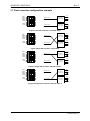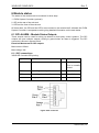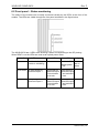
1
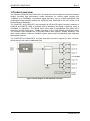
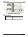
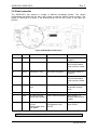
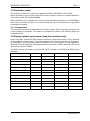
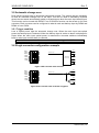
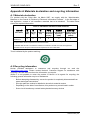
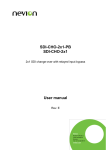
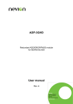
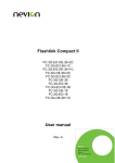
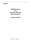
3GHD-OE 3GHD-OE-2 Single and dual 3G-SDI optical to electrical converter User manual Rev. F Nevion Nordre Kullerød 1 3241 Sandefjord Norway Tel: +47 33 48 99 99 nevion.com 3GHD-OE / 3GHD-OE-2 Rev. F Nevion Support Nevion Europe Nevion USA P.O. Box 1020 3204 Sandefjord, Norway 1600 Emerson Avenue Oxnard, CA 93033, USA Support phone 1: +47 33 48 99 97 Support phone 2: +47 90 60 99 99 Toll free North America: (866) 515-0811 Outside North America: +1 (805) 247-8560 E-mail: [email protected] See http://www.nevion.com/support/ for service hours for customer support globally. Revision history Current revision of this document is the uppermost in the table below. Rev. Repl. Date Sign F 5 2015-05-11 MB 5 4 3 2 1 0 4 3 2 1 0 - 2012-06-12 2012-01-20 2011-10-19 2010-03-09 2009-10-23 2009-05-15 AJM AJM AJM AJM AJM AJM Change description Cover page update; DoC removed; no other changes to content Updated chapter 3.5. and 6.1.1 Added MADI transport chapter. Changed optical overload. Updated DIP 5 in 3.2 Updated DIP 2, 4 and 6 in 3.2. First release. nevion.com | 2 3GHD-OE / 3GHD-OE-2 Rev. F Contents 1 Product overview ................................................................................................................ 4 1.1 Product versions .............................................................................................................. 5 2 Specifications ..................................................................................................................... 6 2.1 General ........................................................................................................................... 6 2.2 Optical Input .................................................................................................................... 6 2.3 Electrical Outputs ............................................................................................................ 6 2.4 Standards ........................................................................................................................ 6 3 Configuration ...................................................................................................................... 7 3.1 Single converter .............................................................................................................. 7 3.2 Dual converter ................................................................................................................. 8 3.3 Reclocker mode .............................................................................................................. 9 3.4 Display optical input power (long-haul version only) ........................................................ 9 3.5 Automatic change over ...................................................................................................10 3.6 Single converter configuration example ..........................................................................10 3.7 Dual converter configuration example.............................................................................11 4 MADI transport ..................................................................................................................12 5 Connections ......................................................................................................................13 5.1 Mounting the connector module......................................................................................13 5.2 Terminal format support..................................................................................................13 6 Module status ....................................................................................................................15 6.1 GPI ALARM – Module Status Outputs ............................................................................15 6.2 Front panel – Status monitoring ......................................................................................16 7 RS422 commands .............................................................................................................17 7.1 FLP4.0 block commands ................................................................................................17 7.2 Single converter .............................................................................................................18 7.3 Dual converter ................................................................................................................18 General environmental requirements for Nevion equipment .................................................20 Product Warranty .................................................................................................................21 Appendix A Materials declaration and recycling information .................................................22 nevion.com | 3 3GHD-OE / 3GHD-OE-2 Rev. F 1 Product overview The Flashlink 3GHD-OE and 3GHD-OE-2 is a dual multi bit-rate optical to electrical converter module providing high performance media conversion for various signal formats from 19.4Mbps up to 2970Mbps. Unmatched signal accuracy, even in critical applications with pathological signal patterns makes the 3GHD-OE and 3GHD-OE-2 the first choice for all optical transport demands. The 3GHD-OE- and 3GHD-OE-2 can transport all HD and SD signal formats in addition to DVB-ASI and SMPTE 310M. It performs optical refreshing and signal re-clocking, which is selectable on application. The optical input comes with a sophisticated PIN diode with a sensitivity typically better than –20dBm operating in the 1200-1620nm wavelength range. The module is also available as a long-haul version with typically -30dBm sensitivity. The open system platform of Nevion Flashlink system allows easy interoperability with third party fibre optical systems. The 3GHD-OE and 3GHD-OE-2 unit has also three electrical outputs for each converter, which reduces the need for additional DA’s Figure 1 Block diagram of the 3GHD-OE converter nevion.com | 4 3GHD-OE / 3GHD-OE-2 Rev. F Figure 2 Block diagram of the 3GHD-OE-2 converter 1.1 Product versions Available in the following versions: 3GHD-OE Single converter 3GHD-OE long haul Single converter, long haul 3GHD-OE-2 Dual converter 3GHD-OE-2 long haul Dual converter, long haul nevion.com | 5 3GHD-OE / 3GHD-OE-2 Rev. F 2 Specifications 2.1 General Power +5V DC / 3.2W, max Control Control system for access to setup and module status with BITE (Built-In Test Equipment) Temp. range 0 to +40 °C 2.2 Optical Input Number of inputs 1 on single converter 2 on dual converter Data rate optical 19.4 to 2970Mbps Sensitivity short haul -20dBm Sensitivity long haul -30dBm with laser extinction ratio >10:1 (DWDM) -28dBm (CWDM) Input overload short haul SD/HD: -3dBm, 3G: -5dBm Input overload long haul -7dBm Detector damage threshold >0dBm Optical wavelength 1200–1620nm Transmission circuit fiber Single mode 9/125um Connector return loss >40dB w/SM fiber Connector SC/UPC 2.3 Electrical Outputs Number of outputs 6 on single converter 3 (per converter) on the dual converter Connector BNC Impedance 75 ohm Return loss >15dB @ 5-1485MHz >10dB 1485-2970MHz Peak to peak signal level 800mV ± 100mV Signal polarity 2 inverting, 4 non-inverting on single converter 2 inverting, 1 non-inverting (per converter) on dual converter 2.4 Standards Supported standards for electrical and optical ports: SMPTE292M, SMPTE259M, SMPTE297M, SMPTE305.2M, SMPTE310M, SMPTE424M, DVB-ASI EN50083-9 nevion.com | 6 3GHD-OE / 3GHD-OE-2 Rev. F 3 Configuration 3.1 Single converter The 3GHD-OE can support a number of different broadcast formats. The correct configuration can either be set with a DIP switch or with the GYDA Control System. The layout of 3GHD-OE is shown in the drawing below with the DIP switch to the upper left position. Figure 3 3GHD-OE board layout Switch # Label Function, DIP = ON Function, DIP = OFF Comment 1 RCL1 Reclocker 1 ON Reclocker 1 bypass Reclocker mode for output 1 2 PRI1 No function on this product 3 RCL2 No function on this product 4 PRI2 No function on this product 5 SWP No function on this product 6 7 DOP All LED showing optical input power LED’s normal operation See 3.4 Display optical input power 8 OVR Override GYDA control. Configuration with DIP switch GYDA control. Configuration with GYDA Select configuration from GYDA All DIP switches are off when pointing towards the release handle. nevion.com | 7 3GHD-OE / 3GHD-OE-2 Rev. F 3.2 Dual converter The 3GHD-OE-2 can support a number of different broadcast formats. The correct configuration can either be set with a DIP switch or with the GYDA Control System. The layout of 3GHD-OE-2 is shown in the drawing below with the DIP switch to the upper left position. Figure 4 3GHD-OE-2 board layout Switch # Label Function, DIP = ON Function, DIP = OFF Comment 1 RCL1 Reclocker 1 ON Reclocker 1 bypass Reclocker mode for output 1 2 PRI1 Select input 2 Select input 1 Selects input or in ACO mode selects main input for output 1 3 RCL2 Reclocker 2 ON Reclocker 2 bypass Reclocker mode for output 2 4 PRI2 Select input 2 Select input 1 Selects input or in ACO mode selects main input for output 2 5 SWP Automatic change over Normal operation See chapter 3.5 Automatic change over Select input 2 Select input 1 Selects input for DOP 6 7 DOP All LED showing optical input power LED’s normal operation See chapter 3.4 Display optical input power 8 OVR Override GYDA control. Configuration with DIP switch GYDA control. Configuration with GYDA Select configuration from GYDA All DIP switches are off when pointing towards the release handle. nevion.com | 8 3GHD-OE / 3GHD-OE-2 Rev. F 3.3 Reclocker mode The reclocker can be set to reclock or bypass from DIP#1 and DIP#3 or from GYDA. When reclocker is set to reclock mode jitter from the signal is removed. Accepted bitrates is 270, 1483.5, 1485, 2967 and 2970Mbps. When reclocker is set to bypass the converter accept all bitrates between 19.4 to 2970Mbps. Note that in this mode the jitter is not removed and this can cause problems for equipment following the converter. 3.3.1 Transparency This converter only looks at the bitrates and not the content. This means that any signal with correct bitrates is converted. The product is transparent to data in the ancillary space like embedded audio. 3.4 Display optical input power (long-haul version only) On the long haul version the LEDs can be used as an optical power meter. This is practical under installation of the module. The power measurement is not accurate but can be used as an indication of optical signal strength. Remember to turn this function of after installation. When all LEDs are green the optical input power is more than -6.5dBm. When all LED are off input power is below -25dBm. The DOP can only be turned on from the DIP. DOP is turned on by DIP#7 and DIP#6 select input port. Optical input power Status LED LOS/lock1 LED LOS/lock2 LED More than -6.5dBm Green Green Green Green -7.0dBm to –8.5dBm Yellow Green Green Green -9.0dBm to –10.5dBm Red Green Green Green -11.0dBm to –12.5dBm Green Green Green -13.0dBm to –14.5dBm Yellow Green Green -15.0dBm to –16.5dBm Red Green Green -17.0dBm to –18.0dBm Green Green -18.5dBm to –19.0dBm Yellow Green -19.5dBm to –20.0dBm Red Green -21.0dBm to –22.0dBm Green -23.0dBm to –24.0dBm Yellow Below -25dBm Red nevion.com | 9 3GHD-OE / 3GHD-OE-2 Rev. F 3.5 Automatic change over Dual optical converter has an automatic changeover module. This module has the possibility to have an automatic change over on the input. This can be used in redundancy systems where the user wants automatically switch to a backup port when the main input loses signal. This function can be turned with DIP#5. From GYDA this function can be turned on for each converter. Each converter can be configured to what is main and backup input by DIP#2 and DIP#4 or from GYDA. 3.5.1 Trigger condition Loss of optical power trigs the automatic change over. When the main input loss optical power the backup input is selected. When the backup input is active an alarm is displayed in Gyda. When the main input optical power is restored the converter switches immediately back to main input and the alarm is restored. Note that bit error or loss of lock on reclocker does not trigger the ACO. ON RCL1 PRI1 RCL2 PRI2 SWP 1 3.6 Single converter configuration example I/O1 Optical input O1 O1 Reclocker 3G/HD/SD-SDI Reclocker 2 8 DOP OVR 3G/HD/SD-SDI I/O2 O2 O2 DOP OVR ON I/O1 Optical input O1 O1 I/O2 8 RCL1 PRI1 RCL2 PRI2 SWP 1 Figure 5 OE converter with reclocker O2 O2 Figure 6 OE converter with reclocker in bypass nevion.com | 10 3GHD-OE / 3GHD-OE-2 Rev. F DOP OVR ON I/O1 Optical input 1 Reclocker 1 O1 3G/HD/SD-SDI O1 I/O2 Optical input 2 8 RCL1 PRI1 RCL2 PRI2 SWP 1 3.7 Dual converter configuration example Reclocker 2 O2 3G/HD/SD-SDI O2 DOP OVR ON I/O1 Optical input 1 Reclocker 1 O1 3G/HD/SD-SDI O1 I/O2 Optical input 2 8 RCL1 PRI1 RCL2 PRI2 SWP 1 Figure 7 Dual OE converter, standard setup Reclocker 2 O2 3G/HD/SD-SDI O2 DOP OVR ON I/O1 Optical input 1 Reclocker 1 O1 3G/HD/SD-SDI O1 I/O2 Optical input 2 8 RCL1 PRI1 RCL2 PRI2 SWP 1 Figure 8 Dual OE converter, input swap Reclocker 2 O2 3G/HD/SD-SDI O2 DOP OVR ON I/O1 Optical input 1 Reclocker 1 O1 3G/HD/SD-SDI O1 I/O2 8 RCL1 PRI1 RCL2 PRI2 SWP 1 Figure 9 Single OE converter with DA, input 1 Optical input 2 Reclocker 2 O2 3G/HD/SD-SDI O2 Figure 10 Single OE converter with DA, input 2 nevion.com | 11 3GHD-OE / 3GHD-OE-2 Rev. F 4 MADI transport The card can be used to transport MADI signal. Nevion recommend setting the cable EQ and rec-clocker in bypass. nevion.com | 12 3GHD-OE / 3GHD-OE-2 Rev. F 5 Connections The 3GHD-OE and 3GHD-OE-2 has a dedicated connector module; 3GHD-EO-2-C1. This module is mounted at the rear of the sub-rack. The module is shown in the figure below. Figure 11 Connector module for 3GHD-OE-2 5.1 Mounting the connector module The details of how the connector module is mounted, is found in the user manual for the subrack frame FR-2RU-10-2. This manual is also available from our web site: http://www.nevion.com/. 5.2 Terminal format support The different input and output ports on 3GHD-OE and 3GHD-OE-2 can support a number of formats. The table below show which signal formats are supported on the selected terminals. Terminal format support for single converter: Terminal Function Supported Format Mode OPT1 Optical input SDI, DVB-ASI, Input SMPTE310, Transparent OPT2 Not used. I/O1 Electrical Output I/O2 Reclocked DA output SDI, DVB-ASI, Transparent Output SDI, Transparent Output Wired alarms OC Output O1 O2 –– O1 Electrical Output –– O2 Reclocked DA inverted output GPI ALARM Open Collector Alarms nevion.com | 13 3GHD-OE / 3GHD-OE-2 Rev. F Terminal format support for dual converter: Terminal Function Supported Format Mode OPT1 Optical output SDI, DVB-ASI, Output OPT2 SMPTE310, Transparent I/O1 Electrical Output I/O2 Reclocked DA output SDI, DVB-ASI, Transparent Output SDI, Transparent Output Wired alarms OC Output O1 O2 –– O1 Electrical Output –– O2 Reclocked DA inverted output GPI ALARM Open Collector Alarms Unused inputs should be terminated to avoid alarms triggered by noise. nevion.com | 14 3GHD-OE / 3GHD-OE-2 Rev. F 6 Module status The status of the module can be monitored in three ways. 1. GYDA System Controller (optional). 2. GPI at the rear of the sub-rack. 3. LED’s at the front of the sub-rack. Of these three, the GPI and the LED’s are mounted on the module itself, whereas the GYDA System Controller is a separate module giving detailed information on the card status. 6.1 GPI ALARM – Module Status Outputs These outputs can be used for wiring up alarms for third party control systems. The GPI outputs are open collector outputs, sinking to ground when an alarm is triggered. The GPI connector is shown in figures below. Electrical Maximums for GPI outputs Max current: 100mA Max voltage: 30V 6.1.1 GPI connections 3GHD-OE-2 module GPI pinning: Signal Name Pin # Mode Status General error status for the module. Pin 1 Open Collector This is normally closed. LOS1 Loss of signal on input 1. Pin 2 Open Collector LOS2 Loss of signal on input 2. Pin 3 Open Collector Ground 0V / gnd pin. Pin 8 0V. Figure 1GPI connector nevion.com | 15 3GHD-OE / 3GHD-OE-2 Rev. F 6.2 Front panel – Status monitoring The status of the module can be easily monitored visually by the LED’s at the front of the module. The LEDs are visible through the front panel as shown in the figure below. The 3GHD-OE-2 has 4 LED’s each showing a status corresponding to the GPI pinning. When DIP#7 is on the LEDs are used as an optical power meter. Diode \ State Red LED Status Yellow LED Module is faulty, or N/A module is initializing. Green LED No light Module is OK Module has no power Module power is OK LOS/LOCK1 No input signal on electrical output 1. Input signal on electrical output 1 but reclocker not in lock. Input signal on electrical output 1 and reclocker in lock. LOS/LOCK2 No input signal on electrical output 2. Input signal on electrical output 1 but reclocker not in lock. Input signal on electrical output 1 and reclocker in lock. nevion.com | 16 3GHD-OE / 3GHD-OE-2 Rev. F 7 RS422 commands This card uses the FLP 4.0 protocol to be configured and monitored. See separate documents for definition of this protocol. 7.1 FLP4.0 block commands Common FLP4.0 block for both single and dual converter is listed below. 7.1.1 PIN 0 Optical input 1. Long haul version supports optical level. <identifier> ::= 'pin' <status> ::= ['cd'|'ncd'] [<rssi>'dBm'] 7.1.2 TEMP 0 Board temperature. <identifier> ::= 'temp' <status> ::= ['alarm'] [<temperature>'C'] ['ulim' <temperature>] ['llim' <temperature>] <block command> ::= <upper limit>|<lower limit> <upper limit> ::= 'ulim' <temperature> <lower limit> ::= 'llim' <temperature> 7.1.3 PWR 0 <identifier> ::= 'pwr' <status> ::= [<nominal voltage>'Vnom'] [<voltage>] 7.1.4 PWR 1 <identifier> ::= 'pwr' <status> ::= [<nominal voltage>'Vnom'] [<voltage>] 7.1.5 PWR 2 <identifier> ::= 'pwr' <status> ::= [<nominal voltage>'Vnom'] [<voltage>] 7.1.6 PWR 3 Only for long haul version. <identifier> ::= 'pwr' <status> ::= [<nominal voltage>'Vnom'] [<voltage>] nevion.com | 17 3GHD-OE / 3GHD-OE-2 Rev. F 7.2 Single converter FLP4.0 block for single converter is listed below. 7.2.1 RCL 0 Reclocker for output 1. <identifier> ::= 'rcl' <status> ::= ['en'|'mute'|'bypass'] ['lock'|'lol'] [<bitrate>'Mbps'] ['asi'|'sdi'|'hdsdi'] ['abp' 'on'|'off'] ['rate' 'man'|'auto'] <block command> ::= <set mode>|<set autobypass>| <set mode> ::= 'en'|'mute'|'bypass' <set autobypass> ::= 'abp' 'on'|'off' 7.3 Dual converter FLP4.0 block for dual converter is listed below. 7.3.1 PIN 1 Optical input 1. Long haul version supports optical level. <identifier> ::= 'pin' <status> ::= ['cd'|'ncd'] [<rssi>'dBm'] 7.3.2 CHO 0 Input select for output 1. <identifier> ::= 'cho' <status> ::= [<input>] ['size' 2] [<changeover mode>] [<priority list>] <block command> ::= <set position>|<set priority> <changeover mode> ::= 'auto'|'man' <priority list> ::= 'pri' <input> <set position> ::= 'pos' 'auto'|('man' <input>) <set priority> ::= 'pri' <input> nevion.com | 18 3GHD-OE / 3GHD-OE-2 Rev. F 7.3.3 CHO 1 Input select for output 2. <identifier> ::= 'cho' <status> ::= [<input>] ['size' 2] [<changeover mode>] [<priority list>] <block command> ::= <set position>|<set priority> <changeover mode> ::= 'auto'|'man' <priority list> ::= 'pri' <input> <set position> ::= 'pos' 'auto'|('man' <input>) <set priority> ::= 'pri' <input> 7.3.4 RCL 0 Reclocker for output 1. <identifier> ::= 'rcl' <status> ::= ['en'|'mute'|'bypass'] ['lock'|'lol'] [<bitrate>'Mbps'] ['asi'|'sdi'|'hdsdi'] ['abp' 'on'|'off'] ['rate' 'man'|'auto'] <block command> ::= <set mode>|<set autobypass>| <set mode> ::= 'en'|'mute'|'bypass' <set autobypass> ::= 'abp' 'on'|'off' 7.3.5 RCL 1 Reclocker for output 2. <identifier> ::= 'rcl' <status> ::= ['en'|'mute'|'bypass'] ['lock'|'lol'] [<bitrate>'Mbps'] ['asi'|'sdi'|'hdsdi'] ['abp' 'on'|'off'] ['rate' 'man'|'auto'] <block command> ::= <set mode>|<set autobypass>| <set mode> ::= 'en'|'mute'|'bypass' <set autobypass> ::= 'abp' 'on'|'off' nevion.com | 19 3GHD-OE / 3GHD-OE-2 Rev. F General environmental requirements for Nevion equipment 1. 2. - The equipment will meet the guaranteed performance specification under the following environmental conditions: Operating room temperature range: 0°C to 40°C Operating relative humidity range: <90% (non-condensing) The equipment will operate without damage under the following environmental conditions: Temperature range: -10°C to 50°C Relative humidity range: <95% (non-condensing) nevion.com | 20 3GHD-OE / 3GHD-OE-2 Rev. F Product Warranty The warranty terms and conditions for the product(s) covered by this manual follow the General Sales Conditions by Nevion, which are available on the company web site: www.nevion.com nevion.com | 21 3GHD-OE / 3GHD-OE-2 Rev. F Appendix A Materials declaration and recycling information A.1 Materials declaration For product sold into China after 1st March 2007, we comply with the “Administrative Measure on the Control of Pollution by Electronic Information Products”. In the first stage of this legislation, content of six hazardous materials has to be declared. The table below shows the required information. Toxic or hazardous substances and elements 組成名稱 Part Name 3GHD-OE/ 3GHD-OE-2 鉛 汞 镉 六价铬 多溴联苯 多溴二苯醚 Lead Mercury Cadmium Hexavalent Polybrominated Polybrominated (Pb) (Hg) (Cd) Chromium biphenyls diphenyl ethers (Cr(VI)) (PBB) (PBDE) O O O O O O O: Indicates that this toxic or hazardous substance contained in all of the homogeneous materials for this part is below the limit requirement in SJ/T11363-2006. X: Indicates that this toxic or hazardous substance contained in at least one of the homogeneous materials used for this part is above the limit requirement in SJ/T11363-2006. This is indicated by the product marking: A.2 Recycling information Nevion provides assistance to customers and recyclers through our web site http://www.nevion.com/. Please contact Nevion’s Customer Support for assistance with recycling if this site does not show the information you require. Where it is not possible to return the product to Nevion or its agents for recycling, the following general information may be of assistance: Before attempting disassembly, ensure the product is completely disconnected from power and signal connections. All major parts are marked or labelled to show their material content. Depending on the date of manufacture, this product may contain lead in solder. Some circuit boards may contain battery-backed memory devices nevion.com | 22