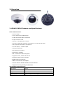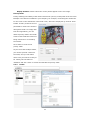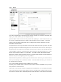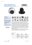
1
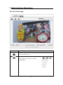
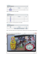
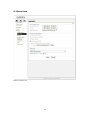
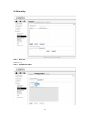
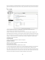
1
Table of Contents
1. Safety Instruction ............................................................................................ 4
1.1
Safety Notice .............................................................................................. 4
1.2
Electromagnetic Compatibility (EMC) .............................................................. 5
2. Overview.......................................................................................................... 6
2.1
ZAVIO P6210 Features and Specifications ...................................................... 6
2.2
ZAVIO P6210 Package Contents ................................................................... 7
2.3
Minimum System Requirement ..................................................................... 8
3. Web Interface Main Menu ............................................................................... 9
4. Setting_Information ..................................................................................... 13
5. Setting_Basic Setup ..................................................................................... 14
5.1
Account .................................................................................................. 14
5.2
Network .................................................................................................. 15
5.2.1 TCP/IP ............................................................................................. 15
5.2.2 PPPoE ............................................................................................. 16
5.3
Date Time ............................................................................................... 18
5.4
Video ...................................................................................................... 20
5.4.1 Video Setting ................................................................................... 20
5.4.2 Profile ............................................................................................ 21
5.4.3 Day/Night ....................................................................................... 22
5.5
Audio ..................................................................................................... 24
6. Setting_Live View ......................................................................................... 26
6.1
Video ...................................................................................................... 26
6.2
Audio ..................................................................................................... 26
6.3
Camera Setting ........................................................................................ 26
6.3.1 Image Setting ................................................................................. 27
6.4
PTZ Setting ............................................................................................. 29
6.4.1 Patrol Settings ................................................................................. 29
6.4.2 PTZ Control ..................................................................................... 30
7. Setting_Playback .......................................................................................... 31
7.1
Network Storage ...................................................................................... 31
7.2
Local Storage .......................................................................................... 33
2
8. Setting_Event ............................................................................................... 34
8.1
Event Server ........................................................................................... 34
8.1.1 Event Server ................................................................................... 34
8.1.2 SD Card .......................................................................................... 36
8.2
Event List ................................................................................................ 38
8.2.1 Event List ........................................................................................ 38
8.2.2 Schedule Recording .......................................................................... 40
8.3
Motion Detection ...................................................................................... 41
8.4
Tampering Detection ................................................................................. 42
8.5
Schedule ................................................................................................. 42
9. Setting_System ............................................................................................ 44
9.1
Maintenance ............................................................................................ 44
9.2
Date Time ............................................................................................... 46
9.3
Security .................................................................................................. 47
9.3.1 Account .......................................................................................... 47
9.3.2 IP Address Filter .............................................................................. 47
9.3.3 HTTPS ............................................................................................ 48
9.4
Network Basic .......................................................................................... 49
9.4.1 TCP/IP ............................................................................................ 49
9.4.2 PPPoE ............................................................................................. 49
9.5
Network Advanced ................................................................................... 50
9.5.1
9.5.2
9.5.3
9.5.4
RTSP .............................................................................................. 50
UPnP .............................................................................................. 52
Bonjour .......................................................................................... 53
DDNS ............................................................................................. 54
9.6
Digital I/O ............................................................................................... 55
9.7
LED ........................................................................................................ 56
9.8
System Log ............................................................................................. 57
10. Video Surveillance Software .......................................................................... 59
3
1. Safety Instruction
Thank you for purchasing this ZAVIO Network Camera. This user manual includes instructions
for using and managing the camera on your network. Updated versions of this document will
be posted to www.zavio.com as they become available. The latest version of this user manual
can also be found on the Installation CD accompanying this product, along with user manuals
in other languages.
1.1 Safety Notices
Before you use this product
This product has been designed with safety in mind. However, the electrical products can
cause fires which may lead to serious body injury if it is not used properly. To avoid such
accidents, be sure to heed the following.
Legal Caution
Video and audio surveillance can be forbidden by laws that vary from country to country.
Check the laws in your local region before using this product for surveillance purposes.
Don't open the housing
Don't try to open the housing or remove the covers which may expose yourself to dangerous
voltage or other hazards.
Don't use the accessories not recommend by the manufacturer
Heed the safety precautions
Be sure to follow the general safety precautions and the “Operation Notice.”
Operation Notice - Operating or storage location
Avoid operating or storing the camera in the following locations:
• Extremely hot or cold places (Operating temperature: -10 °C to + 50 °C [14 °F to
122°F] )
• Exposed to direct sunlight for a long time, or close to heating equipment (e.g., near
heaters)
• Close to water (e.g. near a bathtub, kitchen sink, laundry tub)
• Close to sources of strong magnetism
• Close to sources of powerful electromagnetic radiation, such as radios or TV
transmitters
• Locations subject to strong vibration or shock
In case of a breakdown
In case of system breakdown, discontinue use and contact your authorized dealer.
In case of abnormal operation
4
• If the unit emits smoke or an unusual smell.
• If water or other foreign objects enter the cabinet.
• If you drop the unit or damage the cabinet:
-Disconnect the cable and the connecting cables.
-Contact your authorized dealer or the store where you purchased the product.
Transportation
When transporting the camera, repack it as originally packed at the factory or in materials of
equal quality.
Ventilation
To prevent heat buildup, do not block air circulation around the device.
Cleaning
• Use a soft, dry cloth to clean the external surfaces of the device. Stubborn stains can
be removed using a soft cloth dampened with a small quantity of detergent solution,
then wipe dry.
• Do not use volatile solvents such as alcohol, benzene or thinners as they may damage
the surface.
1.2 Electromagnetic Compatibility(EMC)
FCC Statement
This equipment has been tested and found to comply with the limits for a Class B digital
device, pursuant to Part 15 of the FCC Rules. The limits are designed to provide reasonable
protection against harmful interference in a residential installation.
This equipment generates, uses and can radiate radio frequency energy and, it not installed
and used in accordance with the instructions, may cause harmful interference to radio
communications. However, there is no guarantee that interference will not occur in a
particular installation. If this equipment does cause harmful interference to radio or television
reception, which can be determined by turning the equipment off and on, the user is
encouraged to try to correct the interference by one of the following measures:
• Reorient or relocate the receiving antenna.
• Increase the separation between equipment and receiver.
• Connect the equipment into an outlet on a circuit different from that to which the
receiver is connected.
• Consult the dealer or an experienced radio/TV technician for help.
CE Mark Warning
This is a Class B product. In a domestic environment, this product may cause radio
interference, in which case the user may be required to take adequate measures.
5
2. Overview
2.1 ZAVIO P6210 Features and Specifications
ZAVIO P6210 Feature
• Full HD 1080p
• 1/2.8" Sony Exmor CMOS sensor
• H.264 and Motion JPEG compression
• 30 fps in 1920 x 1080
• 3.6mm, F1.8 megapixel fixed lens
• True day & nightwith automatic removable IR-cut filter and IR LEDs
• Two-way audio and built-in microphone
• 1 x alrm input, 1 x alarm output
• Tampering detection
• RTC with built-in battery
• Excellent PT reliability
• SSL v3 advanced HTTPS encryption
• Supports Firefox, Safari and Mac OS
• Supports Samba network storage
• Multi-lingual user interface
• ONVIF 2.2 and Profile S compliant
• Free 64 channels ZAVIO CamGraba 2.0 NVR software
• Supports True Plug and Play Cloud Solution
ZAVIO P6210 Specifications
Model Name
P6210
Description
2MP Pan/ Tilt IR Mini Dome
Image Sensor
SONY 1/2.8" CMOS
Max Resolution
1920 x 1080 (Full HD 1080p)
6
Video Compression
H.264
MJPEG
Multi-stream Support
4
Max Frame Rate
30 fps @ 1920 x 1080
Lens
3.6 mm, F1.8
Angle of View
81° horizontal
0.05 lux @ F1.8 (color)
Min illumination
0.001 lux (B/W)
0 lux (IR LED on)
Audio Support
Two-way
Built-in mic, line in & out
PoE 802.3af (Class 1)
PoE
12V DC, 1A
Local Storage
MicroSD
Alarm in-/outputs
1/1
Dimensions
φ115 x 70 mm
Motion Detection
Yes
Audio Detection
Yes
Multi-level passwords
Security
HTTPS encryption
Supported Protocols
Video Management Software
Bonjour, TCP/IP, DHCP, PPPoE, ARP, ICMP, FTP, SMTP, DNS,
NTP, UPnP, RTSP, RTP, HTTP, TCP, UDP,3GPP/ISMA RTSP
64 channels ZAVIO CamGraba NVR software included
2.2 ZAVIO P6210 Package Contents
You should find the following items in the packaging of your ZAVIO product.
• Network dome camera
• Quick installation guide
• Installation CD
-CamGraba2.0 NVR software
-Intelligent IP Installer
-User manual
-Language packs
• Mounting and connector kits
• Alignment sticker
• Activation code
If any items are missing, contact your dealer.
7
2.3 Minimum System Requirement
Your computer hardware should meet or exceed the following specifications:
Item
Requirements
CPU
Minimum Intel® Cord 2 Duo or higher(Core i3 or above is
recommended)
Graphic Card
256MB RAM graphic cards(or equivalent on-board graphic cards)
RAM
Minimum 1GB or RAM(2GB or above is recommended)
Operating System
Window 2000, 2003, XP, Vista or Windows 7
Mac OS Leopard10.5
Web Browser
Internet Explorer 6 or later
Note:
• If using Windows 98 or Windows ME, please install IP Installer before using WEB UI to
ensure the system runs normally.
• If not able to view the recorded video file, please install Xvid codec while installing
Intelligent IP Installer. (For Windows 98, ME or 2000 server, the codec might not work
properly. Please download Xvid codec 1.0 from the internet.)
• Please keep updating the latest Windows software and service package. (Ex: Net
Framework, Windows Media Player, Enhance ActiveX Security)
8
3. Web Interface Main Menu
The Live View Page
Toolbar
Function
Click this button to take you back to the camera home page where you
can live view the vide
Click this button to open the administrator
menu page, which can set up all the
configuration
9
This button opens up the integrated
online help providing useful tips on
the various features.
Click this button to pause or resume from pause the live video stream.
The function is also available in VLC mode when you use non-IE browser
Clicking this button will stop the video stream and the video display
turns black (off).The function is also available in VLC mode when you
use non-IE browser
Click on the Record button, if you wish to record the live video to your
computer’s hard drive. When selected, a prompt will request you to
specify the folder in which you want to store the video.
Click OK to begin the recording. The Record button starts flashing,
indicating that the recording is active. Click it again to stop the
recording.
Note: This function is only available in MS Internet Explorer on Windows
systems.
Use this button to take a snapshot of the video. Clicking the button
opens up a window showing the captured frame. Save the image by
clicking on the Save Image button.
The function is also available in VLC mode when you use non-IE browser
The digital zoom function allows magnification of certain areas of the
video. After you click on the magnification icon, a window appears as an
overlay on top of the image.
See below.
10
You can drag the box over the
image, and you can adjust the
magnification by moving the
slider toward “T” (tele-zoom)
or “W” (wide-angle). The
more you move the slider
toward “T,” the further you
zoom in and details appear
larger. It is normal behavior that the image quality is reduced when
using the digital zoom function.
Digital Zoom is only available in MS Internet Explorer Web browsers.
Note: This function is only available in MS Internet Explorer on Windows
systems.
Click this button to view the video in full screen mode. In full screen
mode, the video is stretched to fit the entire screen and all control
graphics and window elements are no longer displayed. To return from
full screen mode, press the ESC key on your keyboard. You can also
right- or left-click any part of the image with your mouse.
The function is also available in VLC mode when you use non-IE browser
Returns the user to the main live video page.
Click this button and the client settings dialog will open.
Profile- Select your preferred
profile from the drop-down list.
The network camera can store
different profiles that provide
different video settings. You can
define these profiles in the
administrator menu, e.g, one profile is for low bandwidth environment
whereas another profile is for maximum quality.
View Size- There are two choices here. “Fit Screen” will keep the video
small so that it will always fit into the view port of the live video page.
“Full Screen” is actually not full screen at all, but it displays the video
stream at it’s
original size. So, if you select a profile that displays
1080p contents and select full screen for the view size, the video will be
rendered at 1920 x 1080 pixels on your screen.
Protocol- Select the transfer protocol here.
Video Buffer- If you turn video buffering on, the video will display
more smoothly at the expense of added delay between the actions in
11
front of the camera lens and when you see them on the screen. If you
want to minimize that delay, you need to set the video buffer to “Off.”
Set- Press on set button to remember the current
position of the camera, the preset positions will be
named with “Preset1” and so on.
Preset- A preset position is a prede fined view that
can be used to quickly steer the camera to a
specific location.
Go- Click on Go button, a drop-down list allows
you to select a certain preset position.
Patrol- Before starting this function, it required to specify Guard tour
settings. Please define the patrol tour in administrator menu first.
A guard tour displays the video stream from different preset positions,
one-by-one, in a predetermined order or at random and for configurable
time periods. The enabled guard tour will keep running after the user
has logged off or closed the browser.
12
4. Setting_Information
The camera’s administrator menu allows you to configure all aspects of your ZAVIO network
camera. This page provides a complete overview of the status of your network camera.
13
5. Setting_Basic Setup
The basic setup allows you to manage the user accounts of your network
camera, define the network parameters, set up the date and time
settings and most importantly, the video settings.
5.1 Account
The ZAVIO network camera allows the creation of different user accounts with different levels
of access to the camera. There are three main user levels. The Viewer account only allows
viewing the live video page of the camera. The Operator account allows viewing the live video
as well as changing the image setup settings, such as brightness, contrast, etc. Only the
Administrator account has full access to all camera settings, including the Settings menu.
You can define up to nine additional user accounts. The user name and password must be
between 4 and 16 characters in length. For each account you can also specify different user
authority (Viewer, Operator or Administrator).
14
Account List:
Click the Add button to create a new user account. A popup window will open up. Here you
type in a user name and a password for the new account. Also, you must define the role of the
new user account. The example shows how we create a guest account that only has viewing
rights, but cannot change any settings.
Click Save to create the new user account.
Highlight an account to either edit or remove it.
Note that the admin user account cannot be removed.
Anonymous Settings:
Enabling this will allow any user to view the live video from the camera live video page
without entering a user name or password. If you do not want to allow this to happen, be sure
to set this option to
“Disabled.”
5.2 Network
On this page you can define the network settings of the camera. By default the camera is set
up to automatically obtain the necessary IP information from the DHCP server (e.g., the
router) in your network. You can, however, set up the IP address and related settings
manually.
5.2.1
TCP/IP
15
Internet Protocol Version 4(TCP/IPv4):
MAC address- MAC address stands for Media Access Control address. This is the unique
hardware address of the camera’s network interface.
Obtain an IP address automatically (DHCP)- This is the default setting. In this
mode the camera obtains the IP information from the DHCP server in your network.
Use the following IP address- Activate this option in order to assign a static IP
address to the camera. You need to enter a valid IP address, subnet mask and default
gateway address in the corresponding fields.
Use the following DNS server address- When you disable DHCP, you also need to
provide the camera with valid DNS settings. The Primary DNS server must be filled out.
It is often the same IP address as the Gateway address.
Internet Protocol Version 6(TCP/IPv6):
IP address- The IPv6 IP address of ZAVIO camera is automatically assigned by
converting the MAC address of the IP camera. User is not able to modify it.
HTTP:
HTTP port number-he default value is 80 and normally there is no need to change it.
If you decide to change the http port to a different value; e.g., 1024, you need to do two
things:
First, after saving the settings you need to reboot the camera via the System -> Initialize
menu.
Secondly, after the reboot is completed you need to connect to the camera using the URL
http://camera_ip:portnumber.
5.2.2
PPPoE
16
PPPoE is the most common form of connection for DSL-based Internet service.
You can use this function to connect the camera directly to a DSL modem. A common
application for this is where the network camera is installed in a remote location where no
network is present. In the location is a DSL Internet connection (DSL modem), but no router
or any other network infrastructure. You can connect the camera to the DSL modem and
enter your DSL account information in the fields below.
PPPoE:
PPPoE- On
IP address- Displays the current IP address obtained from the Internet Service
Provider (ISP). It displays 0.0.0.0 if the camera is not connected to the Internet via
PPPoE.
User ID- Enter the user ID for your DSL service here. The user ID has been given to you
by your ISP.
Password- The password for the DSL account goes here. Re-type the password in the
field below.
DNS Server- Typically, your ISP will send DNS Server information to the camera when
it connects. Some ISPs, however, require entering specific DNS servers manually. In that
case you can activate the option “Use the following DNS server address” and enter the
primary and secondary DNS servers in the fields below (not shown on the screen shot).
17
5.3 Date Time
On this page you can define the time settings of the camera.
Current Date/Time:
Current Date/Time- Displays the camera’s current time.
PC Clock- This is the date and time of the computer you are currently using to connect
to the camera.
Date/Time Format- The format determines how the date/time is displayed on the live
video.
Synchronization Method:
Keep current setting- You don’t want to change the date and time.
Synchronize with client PC- It means to adjust the camera time to your PC. Be aware
18
of the fact that this option sets the time only one time. From that point forward, the
camera time will start to differ from your PC time as time progresses, and occasional
re-synchronization will be necessary.
Manual Setting- Lets you manually enter the time and date. As with the previous
option, the camera’s time will become inaccurate as time passes and you will need to
re-synchronize the time periodically.
Synchronize with NTP- This option is the recommended setting. In this mode, the
camera will synchronize its time settings based on the interval setting (ranging from
once per hour to once per day). The camera obtains the time from the NTP server. You
can use the default value unless your camera is not connected to the Internet, or if a
firewall in your network blocks the outgoing NTP request of the camera. Select “Manual”
and you can enter a different NTP server; e.g., a server in your local network.
Time zone:
Time zone- Select the correct time zone for your location.
Daylight Saving Time- You can define the range of Daylight Saving Time by activating
this option. The camera will adjust the time (move the clock forward or backward by one
hour) depending on the programmed start and end time. If your camera is not equipped
with this feature, you can adjust the time zone manually for Daylight Saving Time.
19
5.4 Video
The following three menus: Video Setting, Profile and Day/Night, allowing defining all
video-related parameters. Note that the Day/Night option as well as other parameters may
not be available on all models.
5.4.1
Video Setting
Image:
Image Rotated- Allows mirroring and rotating the image.
Video Clip Format- Select which video profile the camera should be using for video
clips it records in such as the network storage device, or SD card.
Snapshot Format- Select the video profile used for snapshots (e.g., for JPG upload to
a FTP server).
Overlay:
Overlay- Define what kind of an overlay you want for the live video.
Text Color- Choose between black or white.
Background color- Select from either black, white or transparent.
20
Display Position- Define where the overlay should appear on the live image.
Privacy Mask:
Privacy masking is the ability of the camera to back out (censor) certain parts of the live video.
Example: The camera is installed in your company; for example, overlooking the warehouse.
In one corner of the warehouse is the break room, where the employees go for their lunch
breaks. In many countries it is not
permitted to monitor the workers
during their break. To comply with
laws and regulations, you can
define a privacy mask in the break
area to ensure that this area is not
being monitored or recorded by
the camera.
Click “Add” to create a new
privacy mask.
As you can create multiple masks,
you need to provide a name for
the mask, and you can define
which color you want to overlay to
be. Finally, set the status to
“Enabled” and click “Save” to create and activate the privacy mask.
5.4.2
Profile
21
The ZAVIO network camera allows the creation of video streaming profiles. For each profile
you can define the video resolution, the viewing area and the video codec that is to be used.
Click “Add” to create a new profile, “Remove” to delete a profile or “Edit” to modify an existing
profile.
Video Setting:
Encoding- Your ZAVIO network camera can
encode video in three different formats.
H.264 is the most advanced and efficient
codec delivering excellent image quality and
a small video stream size at the same time.
Normally, this is your preferred choice.
However, you can also select MPEG4 or
MJPEG, e.g., for compatibility reasons.
Resolution- Here you define the video resolution for the profile. Which choices you have
depend on your camera model. Some HD models offer image resolutions of up to 1920
x 1080 pixels whereas standard definition cameras are limited to 640 x 480 pixels.
Maximum frame rate- Type in the number of frames the camera should generate per
second of video. The higher the value, the smoother the video, but the more bandwidth
is going to be required. Valid entries are 1 to 30.
Quality- You can control the image quality of the video by selecting “Fixed Quality”(or
refers to VBR) and defining the image quality by selecting one of the following values
“Medium,” “Standard,” “Good,” “Detailed” and “Excellent.” Or you can choose to specify
the bit rate (fixed bitrate or CBR) of the video the camera must not exceed. In this mode
the camera varies
the image quality automatically to not exceed the specified maximum. With setting fixed
quality plus maximum bitrates, the camera would try to meet the quality requirement
without exceed the certain bitrates.
5.4.3
Day/Night
22
Some ZAVIO network cameras are equipped with active IR LEDs providing the
ability to capture video in complete darkness. Note, that if your camera is not equipped with
IR LEDs, this menu will not be available. Also note that some menu items will vary depending
on your camera model.
Infrared cut-off filters are designed to reflect or block mid-infrared wavelengths while passing
visible light. They are often used in network video cameras to block IR due to the high
sensitivity of many camera sensors to near-infrared light. With the filter in place before the
image sensor, the camera will not be able to pick up IR light, but it generates true color video.
Once the IR cut filter is removed, the camera becomes IR light sensitive and will generate a
black and white image – and it does that even in complete darkness if the IR LEDs are active.
Day/Night:
IR Cut Filter ModeAuto-- The camera decides when to
remove the IR cut filter based on the IR
Cut Filter Threshold you can specify. The
switch delay ensures that the camera only
switches the IR Cut Filter after the specified amount of time has passed.
Night Mode-- This is the opposite of the day mode. If this mode is enabled, the
camera always removes the IR cut filter. As a result, the camera will always be IR
sensitive, regardless of the actual light levels, and the image will be rendered in
B/W mode. Using night mode in day light conditions is not recommended as it
leads to a poor image quality with false and washed out colors.
Day Mode-- In this mode the camera does not remove the IR Cut Filter from the
image sensor regardless of any other settings. So only visible light will pass
through and the image will be in color mode
Schedule-- Select this option, if you wish to control exactly when you want the
camera to engage the night mode. You can use the internal scheduler to define a
time pattern for each day of the week, e.g., no night mode on the weekends, but
night mode from MON to FRI from 21.00 hours to 06.00 hours. The scheduler is
explained in detail later on.
IR Cut Filter Switch Delay- For user to define the time duration (how many seconds)
between IR being turned on or off from the current status.
IR Cut Filter Threshold- Here we use an example to explain how IR cut filter threshold
works. If you set Dark as 30 lux and Bright as 70 lux, that means when luminance is less
than 30 lux, the camera switches to night mode(B/W), and when luminance is more than
70 lux, the camera switches to day mode(color), if the luminance is between 30 lux and
70 lux,the camera stays in current mode.
23
IR ModeAuto-- This ensures that the IR lights go on
whenever the IR cut filter has been removed.
Active-- Keeps the IR LEDs illuminated
regardless of the state of the IR cut filter. To
ensure maximum life of the IR LEDs, this option shouldn’t be used, unless your
camera is installed in a dark environment which requires IR lighting at all times.
Inactive-- When this is selected, the camera will never active its IR LEDs, even if
the night mode is enabled (the IR Cut Filter has been removed). If you have your
own 850nm IR lighting in place already, then you will not need to use the camera’s
integrated IR LEDs and can therefore turn the IR LEDs off.
Schedule-- Select this option, if you wish to control exactly when IR LED turning
on and off by following a certain schedule setting
IR Level- Use this
to control the
lighting pattern of the IR LEDs. Some models allow you to control the center of the image
(“spot”) independently from the outer areas. If you want a more evenly lit image, reduce
the spot level close to 0 and set the wide level to 100. If you want to focus on the center
of the image instead of its surroundings, you raise the spot value and lower the wide
value. If you set IR level as 100, the cover distance of IR light is the farthest; if you set
IR level as 50, the strength of IR light is 50% less.
5.5 Audio
24
Audio Channel:
Full Duplex- Select it for simultaneous communication in both direction between the
connected administrator and IP Camera. It means both parties can speak and be heard
at the same time.
Half Duplex- Select it for communication in both directions, but only one direction at a
time. It can’t receive signal until the transmission has been done. Therefore, once one
party speaks but can’t hear the voice and vice versa.
Talk Only- It narrows down to one way just for talking.
Listen Only- It narrow down to one way just for listing.
Audio Input:
Audio Input Gain- Select the microphone
input gain value you wish in the drop-down
menu, and based on your region to select the
proper codec and save all setting.
Audio Encodingg.711 u-law-- One codec for
“Computer Audio”, used in North America & Japan areas.
g.711 a-law-- Another codec for “Computer Audio”, used in Europe and the rest
for the world.
AMR-- An audio codec of the third generation communication for mobile phone,
while the option selected, your mobile phone will receive the audio files from IP
Camera. And you can choose the bit rate from 4.75k to 12.2k. However, the usage
of this codec will cause frame-rate decreasing.
Off-- Audio file won’t be transmitted by IP Camera.
Audio Output:
Audio Output Gain- Select the speaker output gain value you wish in the drop-down
menu and save it.
Note: The camera does not support echo cancelling, using the full duplex mode may cause
audio feedback.
25
6. Setting_Live View
The Live View menu provides access to the video settings, which are
exactly the same as described in the last section 5.4 & 5.5. It also
provides access to advanced image settings and allows configuring
the view areas that we discussed in the previous section. Note that
depending on your camera model, the options on the screen may
differ from the screen shots in this user manual.
6.1 Video
The same as described in the last section 5.4.
6.2 Audio
The same as described in the last section 5.5.
6.3 Camera Setting
26
6.3.1 Image Setting
Image Enhancement:
The image enhancement controls consist of standard video settings, which you know from a
great variety of products. Click on “Video” to see the camera live video while you adjust the
settings to your liking.
White Balance:
Color Tone- Choose between “Real,” “Cool” or “Warm”. Normally you want to set this to
“Real” as it provides the best representation of natural colors.
Auto White Balance- This parameter controls how the camera interprets colors. You
can choose from the following values: “Auto,” “Fluorescent,” “Incandescent,” “Sunny,”
“Cloudy” or “Sun Shade.” You should select the value that best represents the
environment the camera is installed in. You can also leave the default value “Auto,” as it
typically delivers very good results.
Exposure Setting:
Exposure Frequency- There are four values: “Auto,” “50Hz,” “60Hz” and “Hold
Current.” If your camera is installed so that it’s facing outside, you should select “Auto.”
If your camera is installed indoors, you must select the appropriate light frequency
(either 50 or 60 Hz; e.g., in the US select 60 Hz, in Germany, Poland or Italy select 50
Hz). The hold current option fixes the current exposure settings.
Automatic Exposure- You can manually set the exposure value, which ranges from
0-100 (dark to bright). The default value is 25 and typically provides good results.
Exposure Time- You can define the minimum and maximum exposure time of the
camera’s shutter here. We recommend using the smallest exposure time (e.g., 1/10000
sec) for the min value as it ensures the camera will generate crisp images during day
time conditions in which even moving objects appear sharp and in focus. As for the max
value, the bigger the value, the longer the camera keeps the shutter open in low light
conditions allowing more light to fall onto the image sensor. As a result, the camera can
capture images even in very dark environments. The downside is that moving objects
will appear blurred as the move while the camera’s shutter is open.
Gain- The ZAVIO camera is equipped with an electronic gain mechanism which helps
capture image in dark conditions. The higher the gain, the brighter the image, but the
downside is that the image contains more noise.
Low Light Behavior- When enabled, this opens allows additional control over the
camera when it is running in night mode.
Backlight Compensation (BLC)- In images where a bright light source is behind the
subject of interest, the subject would normally appear in silhouette. BLC allows the
camera to adjust the exposure of the entire image to properly expose the subject in the
foreground. The resulting image may appear overexposed in the background; however,
27
the object of interest is now properly lit.
White Dynamic Range:
WDR stands for Wide Dynamic Range and allows the ZAVIO network camera to capture video
in areas with high contrasting objects; e.g., extremely bright and extremely dark. Activate
WDR by setting it to “Auto” and then adjust the level that controls the amount of WDR
enhancement.
Noise Reduction:
Your ZAVIO camera features a noise reduction algorithm, which helps reduce the graining in
the video, which occurs under low light conditions. Set this parameter to “Night Mode” to only
activate noise reduction when the camera is operating in night mode. You can also select
“Schedule”, “On” (activates noise reduction permanently) or “Off” (deactivated noise
reduction permanently).
28
6.4 PTZ Setting
You may set the speed of digital pan/tilt zoom, and also speed for preset/patrol. The range
goes 1-100 (slow to fast)
6.4.1
Patrol Settings
29
Control Panel:
This can be set up the selected view area in every profile. Besides the viewing window there
is a PTZ control panel to go to the direction you want.
Note: Before operating this function, you must set the resolution beneath 1920x1080, and
move your view area to your desired position.
Preset Position:
Name your every position and click “Add”, you can click “go” to make sure if the preset
position has been written in.
Guard Tour:
Click “Add”, name the tour first then add in the preset position you dedired to form the tour.
You can manually set the PTZ speed and the interval time.
6.4.2
PTZ Control
Speed Control: With higher speed, the camera would move faster.
Pan Speed- 1~5
Tilt Speed- 1~4
Auto Pan Speed- 1~4
30
7. Setting_Playback
The ZAVIO network camera offers an integrated playback feature, which
allows playing back videos from your local HDD, from a network storage
server or the optional SD storage card.Note that only IE can playback
client PC file.
7.1 Network Storage
In the event settings (see section 8) you can define a local network storage drive (NAS) as a
location for the camera to save videos. The video player allows locating recordings quickly
and conveniently on the network storage drive and play back the files right in your web
browser.
There are two folders: “Event” which is for event-triggered recordings, e.g., motion detection
alerts, and “Schedule” which contains recordings that the camera recorded if scheduled
recording is enabled.
Refer to the section 8 “Event” for more details on the setup.
31
Above: Each day has its own folder.
Above: Each hour of the day has its own folder.
Above: Individual videos can be played back by selecting them and clicking the play button.
32
Above: Playback of one event recording in the web browser (MSIE only).
Item
Description
Move one folder up
Refresh the view
Delete the selected file
Select all items in the folder
Playback the selected video
Download selected item to your computer’s hard drive.
7.2 Local Storage
If your camera is equipped with a
local storage option (recording on
an SC card) you can access the
recordings from here. It functions
similarly to the access of files on
the network storage device.
33
8. Setting_Event
Your ZAVIO network camera supports so-called events. When an
event occurs, you can have the camera perform an action, e.g., record
a video to a remote location. This section describes how to set up
event servers, events, motion detection and the scheduler.
8.1 Event Server
First you need to set up an event server, or multiple event servers.
8.1.1
Event Server
Click “Add” to create a new event server.
Add a FTP Server
General:
Name- Provide a name for the server.
34
Server Setting:
Server Type- Select “FTP”
Network Address- Type in the address of
your FTP server.
Server Port- Leave at 21, unless your FTP
server uses a different port.
User Name and password- Provide valid
login credentials for the FTP server.
Passive Mode- Select “On” if your FTP server utilizes passive FTP, which is the most
common method.
Test- Press on Test button to make sure the FTP server information is all correct.
Media Settings:
Here you define what kind of media you wish to upload (snapshot, video or system log), how
many images pre and post event you wish to upload, the image file name and the suffix.
Add a SMTP Server
Server Setting:
Server Type- Select “SMTP.”
Mail Server- Type in the
address of your mail server.
Server Port- Adjust the server
port if necessary. Port 25 is
standard, but your server may
be using different values (not so
uncommon these days as an anti-spam measure).
Authentication- If your mail server requires authentication in order to send email, and
most servers do these days, set authentication to “On” and define the type of
authentication below.
User Name and password- Provide valid login credentials for the email server.
Send mail from- The camera will use this address as its own email address. This email
address does not necessarily need to be a valid address.
Send test email to- Enter the email address to which you want the camera to send the
images and click on Test. If the test succeeds you can provide the information for the
media settings and click “Save”. The actual target email address is defined when you set
up an event in the next section.
35
Add a HTTP Server:
A HTTP server can be used by the
camera to trigger a script on a
remote server if an event occurs.
User name, password and proxy
fields are all optional.
Adding a Network Storage:
Server TypeSelect “Network
Storage.”
Type- Select a valid
type for your
network storage
(either Windows
SMB or Linux NFS).
Network Storage
Location- Enter the
address of your
local storage server as shown on the right.
User Name and password- Provide valid login credentials for the network storage
server.
Create Folder- Type in a folder name in which you want the camera to store files. This
field is optional.
Test- Press on Test button to make sure the NAS information is all correct.
Media Settings- See above.
8.1.2
SD Card
If you want to record video footage on a local SD card, you first must insert the SD card (see
hardware installation guide for details), and then you must set the Memory Card to “on” and
format the card by clicking “Execute.”
36
SD Card:
Card status- Indicate the current available capacity and the maximum capacity if the
SD card
Create Folder- Name a folder to store the video data in SD card, if you leave this
column blank, a folder named with date time will be created
Overwrite- enable this feature to let video data be deleted when SD card is almost full
Noted: Only FAT32 is supported, please do not format the SD card to other format.
Media Setting:
Here you define what kind of media you wish to upload (snapshot, video or system log), how
many images pre and post event you wish to upload, the image file name.
37
8.2 Event List
Now that we have created an Event Server, we can proceed with setting up actual events.
8.2.1
Event List
Click on the “Add” button to begin.
Trigger:
You need to specify the trigger type. The
drop-down list below shows the available options.
Note that depending on your camera model, the
options will vary.
Motion Detection- The camera monitors
the video image for movements and triggers
an alert when it detects motion. Motion
detection needs to be configured first for that to work.
Audio Detection- The camera will monitor the audio sound happening around, one it
exceed a ceratin value, the event will be trigger, audio detection needs to be configure
first for this to work.
Tampering Detection- The camera can detect if it’s being tampered with, e.g., if
someone covers the lens, and triggers an alert when this happens. Tampering detection
needs to be configured for that to work.
Digital Input- If your camera is equipped with digital inputs (see hardware installation
guide), then you can use them as a trigger mechanism. A common example would be to
38
use 3rd party motion detection sensors that trigger the camera to start a recording.
Periodical- This trigger type can be used if you want the camera to perform the same
action over and over again, based on a time period. A typical application would be to
have the camera refresh an image on your web site every 60 seconds.
Onboot- This is a one-time event that is triggered after the camera has restarted.
IR Cut Filter- This trigger event becomes active whenever the camera enters the night
mode and has removed the IR cut filter. For example you can have the camera send you
an email informing you about this event.
Capacity Warning- If you are using the SD Card storage option and you are getting
close to running out of storage space, this event is being triggered. You could use this in
order to send you an email about this so that you can take preemptive and corrective
action.
Network Link Down- This trigger type activates if the camera loses connection to the
network.
IP Notification- This event is triggered when the network is being restarted or the IP
address has changed.
Set min time interval between triggers- define the minimum time interval between
two events
Action:
After you have selected the tripper type, you now have to define the action(s). In other words,
what do you want the camera to do if the event occurs?
Send Image- Instructs the camera to send out images. When selected, you need to
specify whether you want to use FTP, network storage or SD card. You may need to set
up these servers first (see previous section) in order to use them here.
39
Send Notification- This action type uses the HTTP event server. You can use this to
have the camera trigger a script on a server.
Activate Digital Output- If your camera is equipped with digital outputs, then you can
use them to perform an action. You can specific how long you want the camera to trigger
the event once you have selected Digital 1.
PTZ Action- This action type will make the camera to move to/point at a certain preset
position or start run a certain predefined tour when the event occurs.
Schedule:
Here you can define when you want this action to be
active. You can choose between “Always” or a
schedule that you have defined (see “Schedule” a few
pages down).
8.2.2 Scheduled Recording
Schedule Recording:
This feature is allowing the camera to record the video by following a certain schedule such as
always record or record the video during the weekend.
Action:
Define each recorded video file size to save.
You can choose to store the video to NAS or SD card, which need to be pre-configured in
event server.
40
8.3 Motion Detection
The ZAVIO network camera is able to monitor the video footage for movements and trigger
an alert if motion has been detected. This motion detection does not utilize passive infrared,
but instead it relies on a frame by frame comparison of the video footage the camera captures.
You can define more than one motion detection area. The example above shows that
so-called hotspot has been created for the area of the window. When you set up an event for
motion detection, you can select which motion detection area you wish to monitor.
Threshold and sensitivity will need to be set up so that you don’t miss important events and
are not flooded by false alarms either. Finding the right values will require some trial and error.
There are no standard values that simply “will work” as it depends very much on the actual
location and light levels. Generally speaking, increasing the sensitivity while lowering the
threshold will generate more false alarms but it ensures that you will not miss an important
event. Doing the opposite will of course have the opposite effect: Fewer false alarms at an
increased risk or missing an important event.
41
8.4 Tampering Detection
If the image of the camera is obstructed, e.g., because someone covers up the lens or moves
the image out of focus, the camera notices this and generates a trigger alert. You can define
how long you want the alert state to remain active after the event has occurred.
8.5 Schedule
The Network Camera supports event trigger actions that can be based on a schedule. This can
42
be used, as an example, to only activate motion detection between 9 pm and 6 am during
business days and around the clock on the weekends. You can set up individual schedules for
each event type, so that motion detection is activated between 7
pm and 7 am, but tampering detection is only activated between
10 pm and 4 am.
Depending on your camera model, the screen layout will vary
slightly.
There are three default schedules which you cannot delete, but you can modify them.
You can create a new schedule by clicking “Add.”
First you need to provide a name for the schedule (not shown on image). Then select a start
and end time and click on “Add” for the day of the week the schedule is supposed to be active.
As soon as you add a schedule, the timeline turns red, indicating the active schedule. If the
schedule is the same for every day of the week, you can activate the option “Use the same
time schedule every day.”
43
9. Setting_System
The system menu provides access to a variety of system settings of
your ZAVIO network camera.
9.1 Maintenance
44
Restart:
You can restart the network camera by
hitting the restart button. Set Auto Restart
to “On” if you wish to reboot the camera
automatically, and then you specify the
reboot mode. Select “Sequential mode”
and specify after how many days of uptime
you want the camera to reboot. Select
“Schedule Mode” to control when the reboot is to occur in a much more detailed way.
Backup/Restore:
Default- Click this button to restore he factory default settings in this camera. You can
choose to exclude the IP and date & time settings.
Backup- This function allows saving the current configuration of the camera to a file on
your computer’s hard drive. Saving the configuration is useful in case you ever want to
reload a specific configuration; e.g., in order to set up another camera of the same model
and firmware version with the exact same configuration. Since the IP address
configuration is also part of the setting date, you must be careful not to restore the same
settings to two or more cameras when all of them are connected to the same network.
Otherwise, you would be creating an IP conflict in your network.
Restore- With this function, you can reload a previously saved configuration back into
your camera. Click Browse to locate the configuration file and OK to begin the process.
The camera will perform a reboot at the end of the procedure and the new settings will
become effective.
Firmware Upgrade:
From time to time, there will be a new firmware version available for your camera. New
firmware versions can enhance the functionality of the camera, or they can fix problems.
Before you begin, make sure that you have obtained a proper firmware from the ZAVIO web
site. If you are not 100% sure about this, do not proceed. Instead, contact the technical
support team to verify the firmware version. Also, do not perform the upgrade from a
computer that is connected to the network wirelessly, as the connection is inherently less
stable than a cable-based connection. If you have the correct firmware file, make sure that
you un-compress the ZIP file first (if the firmware file is an archive) and you end up with a file
that has an extension *.bin. Click on Browse and select the *bin file. Click on OK to begin the
upgrade process.
Language:
You can replace the language in the user interface of your network camera. On the
Installation CD are different language files starting with “LNG_” and ending with “.lang.” Click
on Browse, select the language you wish to install and then click on OK to begin the process.
45
9.2 Date time
Refer to section 5.3
46
9.3 Security
9.3.1
Account
Refer to 5.1
9.3.2
IP Address Filter
47
Once you enabled it, the listed IP address are allowed or denied access to the network camera.
Add the IP address that you’d like to allow or deny, select allow or deny from the list and save
it.
9.3.3
HTTPS
Secure Sockets Layer (SSL) is a cryptographic protocol that provides security for
communications over networks such as the Internet.
HTTPS is a URI scheme used to indicate a secure HTTP connection (SSL encrypted). It is
syntactically similar to the http:// scheme that is normally used for accessing resources using
HTTP. The differences are that SSL-encrypted connections always begin with https:// instead
of http://. HTTPS connections use TCP port 443 by default, compared to standard HTTP
connections, which use port 80.
Create & Install:
Create a self-signed certificate for HTTPS to recognize.
Installed Certificate:
Display or remove the properties of the installed certificate.
HTTPS Connection Policy:
Set HTTPS connection policy for different level of users.
To use the HTTPS encryption, please set up “Create self-signed certificate” for the first time
you use the HTTPS function, and then set up the connection policy for different users.
Note: When enable HTTPS with RTSP on mode, the IP Camera only protect the setting such as
username and password and do not protect video and audio. When enable HTTPS with RTSP
off mode, the IP Camera will protect all setting including video and audio.
48
9.4 Network Basic
9.4.1 TCP/IP
Refer to section 5.2.1
9.4.2 PPPoE
Refer to section 5.2.2
49
9.5 Network Advanced
9.5.1
RTSP
General:
RTP Port Range- The default value of port range is 5000 ~ 7999 and can be changed
from 1124 to 65534.
RTSP Port- RTSP stands for Real Time Streaming Protocol. RTSP is supported by most
media clients, such as Real Player, VLC and QuickTime. If you only plan to view the
camera video with your Web browser or with one of the provided software utilities, you
do not need to activate this option. The default value is 554 and can be changed from
1124 to 65534.
RTSP Configuration:
This option allows you to set up the URL for each profile and define whether or not you want
to enable or disable authentication. By default, the video URL and profile number are related,
e.g., profilex = video.prox, but you change it any way you like. Based on the default URLs,
access to the RTSP streams would be done like this:
rtsp://camera_address:554/video.pro1
rtsp://camera_address:554/video.pro2
rtsp://camera_address:554/video.pro3
rtsp://camera_address:554/video.pro4
50
If authentication is enabled, the URLs will change as follows:
rtsp://username:password@camera_address:554/video.pro1
[...]
rtsp://username:password@camera_address:554/video.pro4
Multicast:
Your ZAVIO network camera supports multicast streaming. The differences between
multicast and unicast streaming are explained below. Note that for most users the multicast
streaming feature will not be of any importance and most likely the required network
infrastructure for proper multicast streaming is not in place.
Unicast- For each connected computer there is a separate
TCP/IP connection. When 20 computers are connected to the
camera, the camera has to create 20 different connections,
and the camera has to send out the same video data to each of
the 20 computers. This not only puts a significant load on the
camera, it also creates massive amounts of data that need to be transferred over the
network to each connected client.
Unicast is still the most common model when using a network camera, since most times
only a recording device (DVR or NVR) is connected to the camera and perhaps
connections from just a small number of computers.
Multicast- Here the initial stream is sent to the router only,
which creates optimal distribution paths for datagrams sent
to a multicast destination address. Whether one or 300 PCs
are connected to the video stream does not matter. The
bandwidth and load of
the local camera is unaffected.
Because of this, multicast is the preferred choice for broadcast-type applications.
Status- Enable or disable the multicast function here.
Access Name- This is the stream URL. It depends on the profile selected and can be
modified.
Multicast Address- Type in the multicast server address here.
51
Video Port- You can specify the video ports here, or you can use the auto value, which
should be good for most occasions.
Audio Port- You can specify the audio ports here, or you can use the auto value, which
should be good for most occasions.
Time-To-Live- The Time-To-Live value defines how long multicast traffic will expand
across routers. Routers have a TTL threshold assigned and only datagrams with a TTL
greater than the interface's threshold are forwarded.
9.5.2
UPnP
UPnP stands for Universal Plug and Play. A UPnP-enabled device, such as your network
camera, announces its presence in the local network to other computers that support UPnP as
well. The operating systems Windows XP, Windows Vista and Windows 7/8 support UPnP.
When the network camera is connected to the network, Windows will alert the computer user
of the presence of the new device (a new icon will be added to your My Network Places folder)
and lets the user connect to the device instantaneously.
Furthermore, UPnP has the ability to instruct the router or firewall to open certain ports, so
that a party from the outside world can contact a device on the local network, such as the
network camera.
UPnP port forwarding is not supported by all routers, however. So, depending on your router
or firewall, you may or may not be able use this function, also, opening ports in any router or
firewall increases the risk of an intruder successfully breaking in to your network. UPnP
automates this task and leaves it to the devices to negotiate which ports to open. Since this
is done without any form of authentication, enabling UPnP port forwarding in your router is
not necessarily a good idea in a security-sensitive environment. You can always open
individual ports in your router or firewall manually.
In the camera UPnP is enabled by default. UPnP port forwarding is disabled by default. When
52
you enable UPnP port forwarding, the screen will reveal additional options. These are the
ports the camera will instruct the router to open. Depending on the camera model, you may
see different ports. The new H.264 Megapixel cameras have a simpler port model and require
fewer ports than the other models. Normally there is no need to change any of these ports,
unless you know that a port is already in use by a different device or application.
9.5.3
Bonjour
UPnP Bonjour is a service that, just like UPnP, helps to find the network camera on the
network. Bonjour is available for Windows, but is more commonly used for MacOS..
Bonjour:
Bonjour On- Enables the service (on by default).
Bonjour Off- Disables the service
Device name- Enter the name of your camera here. This is the name the Bonjour
service will display. If you have more than one camera installed in your network, this is
an easy way to differentiate among the cameras.
53
9.5.4
DDNS
If you are not planning on connecting to the network camera over a remote connection, but
only in your local network, you can skip this section.
Dynamic DNS is a network service that provides the capability for a networked device, such
as a router or computer system, to notify a domain name server to change, in real time
(ad-hoc) the active DNS configuration of its configured host names, addresses or other
information stored in DNS.
In simpler terms: Users of private Internet services are often faced with a problem: The ISP
typically changes the IP address assigned to the user based on a time interval. This may be
as often as once every 24 hours or as seldom as once every 30 days. For the average user this
is not a problem. However, if you want to be able to connect to the local camera (e.g., in your
house) from a remote location (e.g., the office), you need to know under which Internet
address the camera can be reached. However, you don’t know what the current Internet IP
address is. So you are beginning to see the problem.
DDNS solves this problem by allowing you to create a domain name for your home network,
which you can always use to access the camera. To use the DDNS function, you will need to
do the following two things.
First, create a DDNS hostname with a DDNS service provider
Secondly, set up a DDNS client in the home network that contacts the DDNS service provider
and updates the IP information.
If the router in your home network is equipped with a DDNS client, we recommend using the
router instead of the camera. Most SOHO routers are equipped with a DDNS client and since
the router is in direct control of handling the Internet connection, it’s the device best suited
54
for the DDNS task.
Server Name- Select the DDNS provider of your choice. In our example we use
no-ip.com.
User ID- Enter the same user name here that you use to log in to your account settings
on www.dyndns.org. Do not enter your DSL user account information here.
Password- Enter the password for your no-ip.com user account here. Re-type the
password in the field below.
Host name- You need to enter the full host name that you have created in your
no-ip.com account here.
Periodic Update- You can either specify the time in minutes after which the camera will
update its IP information with the DDNS provider, or you can leave the setting as “Auto”,
which is recommended.
Click “Save” to activate the settings. Reboot the camera to activate the DDNS settings.
After a reboot you may need to wait for a few minutes before you can access the camera
with the new domain name.
9.6 Digital I/O
If your ZAVIO network camera is equipped with a digital I/O interface, you can configure the
connections on this page. The screen shows the current status of input 1 and output 1. The
screen also allows you to define the “normal” state of the port. The normal state can be
viewed as the “non-alert-state.”
55
9.7 LED
You can enable or disable the operation LEDs on your ZAVIO network camera. Hiding the LED
indicator will make the camera appear to be offline while in fact it is operational and captures
video.
56
9.8 System Log
The Network Camera features a log function for system messages. These are
system messages about the camera start-up procedure, e-mail deliveries, FTP
uploads, motion detection and more. The camera stores the messages in its internal
memory and displays them on the system log screen. Since memory is limited, the
messages will eventually be truncated. If you need to log all the system messages
on a remote server (e.g., for permanent record keeping of alarm events or for
troubleshooting purposes), you can utilize the remote log functionality.
Enable Remote Log:
Server Name- Type in the network address of the system log server. Enter the address
without any leading characters, such as http://.
Server Port- The standard port for this protocol is 514. If your system log server is set
up differently, you can change the value here.
Current Log:
This text box displays the real-time log of the camera messages.
57
The remote log function uses the System Log Protocol, which is
a standard for forwarding log messages in an IP network.
System Log is a client/server protocol. The System Log sender
(the Network Camera) sends a small (less than 1KB) textual
message to the System Log server.
This user manual shows one example of a System Log server, the 3CDaemon utility by 3Com
Corporation (Download Location:
http://support.3com.com/software/utilities_for_windows_32_bit.htm).
After the installation of 3CDaemon, the main program window opens and the program is
ready to receive System Log messages from the network camera.
The messages shown here are the same messages that are displayed in the Web browser.
58
10.
Video Surveillance Software
The ZAVIO Network Camera ships with a surveillance application that can monitor and record
up to 64 network cameras.
ZAVIO CamGraba 2.0, the free-bundled network video management software, works
perfectly with all ZAVIO network products. ZAVIO CamGraba 2.0 is designed with reliable
performance and easy-to-use features offering efficient video management solution for
diversely small-to-mid size IP surveillance applications. In addition, ZAVIO CamGraba Viewer
is available to download from iPhone app store and Android app market.
A detailed user manual is located on the Installation CD in the User Manuals folder. It contains
installation instructions and information on the use of the software.
59
60