1
USER MANUAL
Annuncicom
Network-based, stand-alone intercom system for
custom home installations and commercial applications
Firmware: Version 4.07
Released: October 2013
Supports:
•
•
•
•
•
•
•
•
Annuncicom 100
Annuncicom 200
PS1
Annuncicom 60
Annuncicom 155
IPAM 100
IPAM 102
IPAM 302
Annuncicom User Manual Version 4.07
Table of Contents
1 Introduction ............................................................................................................................................................ 5
1.1 About the Annuncicom............................................................................................................................................. 5
1.2 Features................................................................................................................................................................... 5
1.3 Installing the Device................................................................................................................................................... 6
1.4 Additional Documents............................................................................................................................................... 6
1.5 Preloaded Firmware.................................................................................................................................................. 6
1.6 About this manual..................................................................................................................................................... 6
2 Controlling the Annuncicom .................................................................................................................................... 7
2.1 User menu interface.................................................................................................................................................. 8
2.2 Status and control..................................................................................................................................................... 8
3 Configuration ........................................................................................................................................................ 11
3.2 Configuration Overview........................................................................................................................................... 11
3.3 Basic Settings.......................................................................................................................................................... 12
3.4 Advanced Settings................................................................................................................................................... 13
3.5 Table Settings......................................................................................................................................................... 28
4 Reverting to factory defaults .................................................................................................................................. 30
5 Rebooting the device ............................................................................................................................................. 31
6 Updating the device ............................................................................................................................................... 32
6.1 STEP 1.................................................................................................................................................................. 32
6.2 STEP 2.................................................................................................................................................................. 32
6.3 STEP 3.................................................................................................................................................................. 33
6.4 STEP 4.................................................................................................................................................................. 33
7 The How To section ........................................................................................................................................... 34
7.1 How to set the Annuncicom for listening using WinAmp............................................................................................. 34
7.2 How to listen using Windows Media Player................................................................................................................ 35
8 Application notes ................................................................................................................................................... 38
8.1 Two station intercom.............................................................................................................................................. 38
8.2 Door station and control station............................................................................................................................... 42
9 Advanced user section ........................................................................................................................................... 47
9.1 Network configuration using serial cable supplied........................................................................................................ 47
9.2 Network configuration using Telnet........................................................................................................................... 49
9.3 Control APIs for serial and Ethernet.......................................................................................................................... 49
9.4 Expert settings........................................................................................................................................................ 50
10 FAQ and Troubleshooting .................................................................................................................................... 51
11 Dictionary ........................................................................................................................................................... 52
12 Legal Information ................................................................................................................................................. 54
Annuncicom User Manual Version 4.07
Annuncicom User Manual Version 4.07
1 Introduction
1.1 About the Annuncicom
Congratulations on the purchase of your Annuncicom from Barix AG.
What exactly is the Annuncicom? The Annuncicom is a network-based intercom, featuring fast setup,
operation over existing network connections, flexible use and easy reconfiguration.
The Annuncicom can work with other Annuncicom devices in a standalone configuration or can
seamlessly inter-operate with IT equipment like PCs.
Up to two buttons (Talk & Door, Talk & Emergency etc) plus relay output interface are available, which
allow the use of the Annuncicom in talk-back and door entry solutions.
Applications include
- Door intercom, talking over TCP/IP networks
- Alarming in public infrastructure, for example airports
- Remote paging connectivity via networks
- Residential intercom with network connectivity
- Automatic announcement systems
Each device can be configured to directly talk to up to 8 targets, via broadcast, or with the last calling
station.
An unlimited number of communication partners can be selected via web browser or serial interface
(directory connection).
The Annuncicom is the ideal solution to monitor entrances and to provide intercom and alarming
functionality in large residential, commercial and military building complexes like airports, office
buildings, malls and residential housing areas. It can also be used along highways or in tunnels to
provide IP based intercom capabilities.
No need for extra wiring when using existing network infrastructure or operating wireless, hence saving
implementation time and costs. Using only standard TCP/IP protocols, connecting remote facilities is
simple, and no changes to the existing WAN infrastructure are necessary.
1.2 Features
• Semi duplex two-way communication using mono audio streams.
• Choice of MPEG, G.711 and PCM audio formats.
• 10/100 Mbit Ethernet connection
• Two button input (e.g. Talk & Door) plus relay output interface
• Controllable via a standard web browser (PC, PDA, Web tablet) or via a serial port
• Line in, Line out, built in amplifiers for microphone and speaker
• Features SonicIP® and IPzator™ technology
• Easy integration into existing IT and intercom infrastructure
BARIX AG | 28. Jan. 2014 | Introduction | Page 5/54
Annuncicom User Manual Version 4.07
1.3 Installing the Device
For the installation of the Barix Annuncicom devices please refer to the corresponding “Quick Install
Guide”. A printed version is included in the box and can also be downloaded from our site
www.barix.com.
1.4 Additional Documents
Technical specifications can be found in the corresponding product sheet which can be downloaded
from our site www.barix.com.
For detailed technical information on the CGI application programming interface (API) please download
the “Annuncicom Technical Documentation” from our website.
1.5 Preloaded Firmware
Barix pre-loads the “Annuncicom” firmware (from V4.06) on the Annuncicom 100 and Annuncicom 60 in
a multi package with SIP. Please choose the annuncicomic from the REBOOT page and reboot. If other
HW is being used then the factory firmware will have to be replaced.
Before continuing with this manual make sure that the firmware version is up to date and corresponds
with this manual. If not please proceed to the chapter “Updating the Device” in order to do so.
1.6 About this manual
1.6.1 Links to chapters
References to chapters (e.g. X Chapter name) are red and underlined and serve as direct links when
viewed in Adobe Acrobat Viewer. Click on the link to jump to the referenced chapter.
1.6.2 Bookmarks pane in Adobe Acrobat
The complete “Table of Contents” is available in Adobe Acrobat Viewer. Click on the “Bookmarks” pane
tab on the left side of Adobe Acrobat Viewer to open it. Click on any bookmark to directly jump to the
corresponding part of the manual.
1.6.3 Chapter overview
This technical documentation is divided into the following chapters:
• 1 Introduction (This chapter)
• 2 Controlling the Annuncicom (Controlling the Annuncicom via the WEB UI)
• 3 Configuration (How to configure the Annuncicom)
• 4 Reverting to factory defaults (Recovering the initial configuration)
• 5 Rebooting the device
• 6 Updating the device (How to update or change from “standard firmware”)
• 7 The “How To” section (How to “listen” from Winamp or Media Player)
• 8 Application notes (Two common applications)
• 9 Advanced user section (Serial port and Telnet Network configuration)
• 10 FAQ and Troubleshooting
• 11 Dictionary (technical names and expressions used in this manual)
• 12 Legal Information
BARIX AG | 28. Jan. 2014 | Introduction | Page 6/54
Annuncicom User Manual Version 4.07
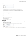
2 Controlling the Annuncicom
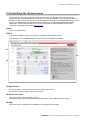
The Annuncicom has a local web server built in so that you can control it from anywhere on your
network using a standard web browser (from your PC, PDA or web tablet). This section describes the
WEB UI as seen on the Annuncicom 100. For other devices the pages are modified depending on what
features are supported on that particular HW. In which case the help pages provide the required
information. The Annuncicom web server can be customized to meet installation requirements.
Download the development kit from www.barix.com .
STEP 1
Open your web browser.
STEP 2
Type in the IP address of the Annuncicom in the address bar then press Enter.
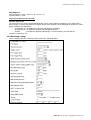
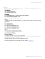
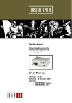
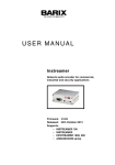
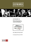
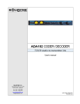
You should now see the Home page of the Annuncicom in the browser window:
F1
F3
F2
F1 Menu Frame
This frame allows selection of the Annuncicom web server features
Click on the selection to go to the relevant section.
F2 Status and control
This frame shows the current device status.
Several links allow control and simulation of button inputs, relay output and serial signals.
F3 Help
This frame shows the help for the available links in the device status page.
BARIX AG | 28. Jan. 2014 | Controlling the Annuncicom | Page 7/54
Annuncicom User Manual Version 4.07
2.1 User menu interface
➢
➢
➢
➢
➢
➢
The menu frame is loaded once and remains in place as the following features are selected:
Home
Configuration
Status
Defaults
Update
Reboot
2.1.1 Red Bar
On the red bar is displayed the HW type, MAC address and the FW version loaded
2.1.2 Barix Logo
Clicking the Barix logo will bring you to the Barix homepage. (www.barix.com)
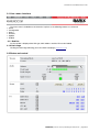
2.2 Status and control
BARIX AG | 28. Jan. 2014 | Controlling the Annuncicom | Page 8/54
Annuncicom User Manual Version 4.07
2.2.1 Stream
Shows the streaming mode and the audio format.
2.2.2 Audio
Shows the current Audio Input and Output Peak levels in dB, current volume in % and the audio input
source.
Volume Slider
In the audio section there is an imbedded volume slider. The volume level can be adjusted in steps of
5% and has immediate affect. Click closer to the + (plus) sign for higher volume or closer to the – (dash)
sign for lower volume. Clicking on the – (dash) sign decreases the volume by 5%. Clicking on the +
(plus) sign increses the volume by 5%. The changes are tempory. On device reboot the volume returns
to its configured setting.
2.2.3 Status
Shows the current audio status.("IDLE", "TALKING", "TALKING SUPPRESSED", "FORCED TALKING"
and "LISTENING"). Click the "FORCE" link to force talking This overrides the "LISTENING" mode, e.g.
when an other device is talking to this device. Click the "TALK" link to start talking. Click the "STOP"
link to stop talking. The Status indicator has the following meaning: GREY: not talking, GREEN: talking,
RED: forced talking. On "send always" the buttons are not visible and the status is permanently set to
"FORCED TALKING"
Table
Select the streaming table by number. Go to the configuration Basic or Table settings to create table
entries.
Entry
Select "All" for talking to all configured entries within the table. Select a particular number to talk only to
that entry.
2.2.4 I/0
The Annuncicom software supports 2 digital inputs and 1 digital output. In addition CTS and RTS can
also be used as digital input/output signals. Any signals not provided by the Annuncicom HW are not
displayed.
Button 0 and 1
Click the "SET" link to simulate the button being pushed.
Click the "CLR" link to simulate the button being released.
The indication next to "BUTTON" has the following meaning:
GREY: released, GREEN: pushed (simulation is not shown!)
Relay
Click the "TOGGLE" link to activate the relay for the "Relay toggle duration" time, adjustable in
"Settings" under "I/O". Click the "SET" link to activate the relay, the "CLR" link to deactivate the relay.
The indicator next to "RELAY" shows the physical status of the relay: GREY for inactivated, GREEN for
activated.
BARIX AG | 28. Jan. 2014 | Controlling the Annuncicom | Page 9/54
Annuncicom User Manual Version 4.07
CTS IN (RS-232)
Click the "SET" link to simulate CTS being activated. Click the "CLR" link to simulate CTS being
deactivated. The indicator next to "CTS IN" shows the physical status of the CTS GREY: inactive,
GREEN: active (simulation is not shown!)
- not activated
- activated
RTS OUT (RS-232)
Click the "SET" link to activate RTS. Click the "CLR" link to deactivate RTS. The indicator next to "RTS
OUT" shows the physical status of the RTS:
- not activated
- activated
2.2.5 Supervision
One of the range of Annuncicom HW, the Annunciocm 155, also supports supervision of microphone,
speaker and temperature. On the Annuncicom 155 the following fields are also displayed.
MIC
This field shows the status of the microphone:
- microphone detected and operating properly
- microphone not attached or short-cut detected
SPEAKER
This field is available only on devices supporting supervision. Shows the status of the attached speaker.
The speaker is supervised with an in-band tone. The supervision must be configured in the Audio
section and is by default off. The following values are displayed:
- supervision switched off or no value available yet
- speaker detected and operating properly
- speaker not attached or short-cut detected
TEMP
Shows the device's internal temperature in degrees centigrade. The information is available only on
devices supporting supervision.
BARIX AG | 28. Jan. 2014 | Controlling the Annuncicom | Page 10/54
Annuncicom User Manual Version 4.07
3 Configuration
To enter the Annuncicom device configuration log onto its local web server.
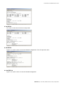
3.1.1 STEP 1
Open your web browser
3.1.2 STEP 2
Type in the IP address of the Annuncicom and press Enter
Example: 192.168.11.164
3.1.3 STEP 3
Click the Config button
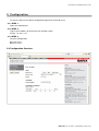
3.2 Configuration Overview
BARIX AG | 28. Jan. 2014 | Configuration | Page 11/54
Annuncicom User Manual Version 4.07
3.2.1 Configuration choices
From software version 4.06 the configuration is simplified to the following options:
➢ Basic Settings
Allowing the configuration of a simple use case, typically with two devices
➢ Advanced Settings
Allowing the configuration of all the parameters except the routing tables
➢ Table Settings
Allowing the configuration of all 64 table entries.
Within each of these 3 configuration groups, any parameters can be changed on multiple pages and applied
once. This is an improvement over previous versions of the software which required parameters to be saved
for every page. Use the “Apply” button to save all changes made in the current group. Use “Cancel” to
cancel all changes.
3.2.2 Parameters
If Advanced or Table Settings is chosen a further menu choice is available to select a group of parameters.
The menu selection is highlighted.
3.2.3 Help
Help is provided to configure each parameter. The help information is updated in parallel with the parameter
menu selection.
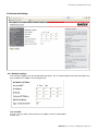
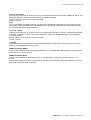
3.3 Basic Settings
The Basic Settings allow the most common parameters to be set. For a description of the parameters refer to
sections 3.4 Advanced Settings and 3.5 Table Settings below.
BARIX AG | 28. Jan. 2014 | Configuration | Page 12/54
Annuncicom User Manual Version 4.07
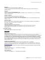
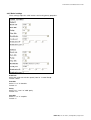
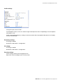
3.4 Advanced Settings
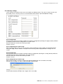
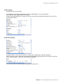
3.4.1 Network settings
Here a Static IP address can be configured for the device. This is recommended so that the device does not
have to obtain an IP address on every power-up.
Use SonicIP®
If set to "yes", the device will announce its IP address over the audio output.
Default: "yes"
BARIX AG | 28. Jan. 2014 | Configuration | Page 13/54
Annuncicom User Manual Version 4.07
IP Address
Enter the 4 values of the desired device IP address e.g.:
"0.0.0.0" for automatic discovery (DHCP/Bootp, IPzator, AutoIP), "192.168.0.12" for an internal LAN
Default: "0.0.0.0"
Netmask
Enter the 4 values of the desired Static IP e.g.:
"0.0.0.0" for a default Netmask depending on the IP Address used, "255.255.255.0" for a C class network
Default: "255.255.255.0"
Gateway IP Address
Enter the 4 values of the desired Gateway IP address e.g.:
"0.0.0.0" for no Gateway, "192.168.0.1" for a the LAN Gateway.
Note: The Gateway has to be set only when connecting to other devices over the WAN (through a router).
Default: "0.0.0.0"
DHCP Host Name
Name of the device sent in a DHCP request. If left empty, a name based on the device's MAC address is
generated automatically. Enter up to 15 Characters.
Type of Service/DSCP
ToS value used for TCP and UDP streaming.
DSCP(Differentiated Service Code Point) supersedes IP4 ToS value and uses the same byte.
check for DSCP services available in your network to set this value. Valid values are 0-63.
Default value is 0.
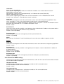
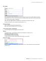
3.4.2 Audio settings
These settings adjust the audio input and output.
Input section
Input source
Choose the desired input source.
All input sources except "Line stereo" are mono. If you are using an Annuncicom 200 a further option is
available to select the SUB connector for Aiphone use. If this is selected the audio output will also be directed
to the SUB interface. NOTE: Aiphone panels have a "ring" button which when pressed produces a signal on
the SUB interface. This signal is used to trigger digital input 0 on the Annuncicom. However, this signal may
also be triggered by audio input and is, therefore, filtered out by the FW. For this filter to be effective, Aiphone
panels should only be connected to the SUB interface if the SUB interface is selected as an input source.
Default setting is "Mic".
Speaker Also As Microphone
A speaker can be wired to an Annuncicom so that it can also be used as a microphone.
In this case connect the speaker between (+) (A5) and ground (A3 or 4) instead of between (+) and (-) and
connect (+) to the Microphone Input (A1). You will find the pin outs in the Annuncicom Quick Install guides.
Barix Annuncicom Family
For proper operation of the device this feature should only be selected if the speaker is wired as described.
Microphone gain
Choose the desired gain ("21" - "43.5" dB) for the microphone.
Default setting is "21" dB.
A/D amplifier gain
Choose the desired gain ("-3" - "19.5" dB) for the A/D amplifier.
BARIX AG | 28. Jan. 2014 | Configuration | Page 14/54
Annuncicom User Manual Version 4.07
Loop Input to Output
Choose "Yes" to hear the attached input on the local Line Out (For testing only, feedback may occur when
using a speaker).
Default setting is "No".
Encoding
Choose between different encoding types (audio compression) and sampling frequencies.
From "MPEG1 / 48 kHz" down to "MPEG2 / 16 kHz" and "uLaw", "aLaw" or "PCM" at 8 or 24 kHz.
Default setting is "MPEG2 / 22.5 kHz".
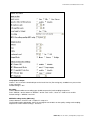
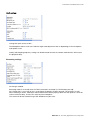
MPEG Encoding Quality (MP3 only)
Choose between "0 lowest" and "7 highest" in steps of 1.
The Encoder Quality table below shows the average bit rate in kbit/s for the quality settings and sampling
frequencies in kHz. Default setting is "0 lowest".
BARIX AG | 28. Jan. 2014 | Configuration | Page 15/54
Annuncicom User Manual Version 4.07
Qual.
0
1
2
3
4
5
6
7
44.1
65
68
73
80
90
105
125
140
22.05
35
38
40
45
50
60
75
90
Output Section
Volume
Choose between "0"% and "100"% in 5% steps.
Default: "50"%
Bass
Choose between "-10" and "10".
Default: "0"
Treble
Choose between "-10" and "10".
Default: "0"
Loudness Level
Choose between "0" and "20".
Default: "20"
Output Mode
Choose one of the "Mono", "Stereo" or "Bridge" settings.
The "Mono" mode produces a monophonic output signal out of both channels.
The "Stereo" mode lets both channels through.
The "Bridge" mode creates a mono differential left/right signal for connecting a single double-impedance
speaker as a bridge between left and right channel.
Note: The "Stereo" and "Bridge" settings apply for stereo hardware only.
The output mode should correspond to the audio encoding used. The MPEG encoding is stereo, whereas
uLaw, aLaw and PCM can transmit only monophonic signal.
Advanced Encoder Settings
MP3 Frame CRC
If set to "enable", the encoder will include the CRC-16 in each MP3 frame.
Default setting is "enable".
MP3 Bitreservoir Mode
The Bit reservoir is used to compensate the differences between the predefined frame sizes. If set to "used",
the encoder will use the bit reservoir.
Default setting is "kept empty”.
MP3 Copyright Protection
"Enable" or "disable" the copyright protection bit in the MP3 bitstream.
Default setting is "enable".
MP3 Stream Type
Select between a "copy" or an "original" bitstream in order to set the appropriate bit in the MP3 bitstream.
Default setting is "copy".
BARIX AG | 28. Jan. 2014 | Configuration | Page 16/54
Annuncicom User Manual Version 4.07
MP3 Emphasis
Select emphasis "none", "50/15 us" or "CCITT J.17".
Default setting is "none".
Supervision (Annuncicom 155 only)
Speaker Supervision
On the Annuncicom 155 the attached loudspeaker can be supervised by the hardware. The supervision is
done using a 11Hz tone injected into the signal. Status of the speaker is then displayed on the device's home
page. Configure the supervision:
• permanently off - to disable the 11Hz tone and speaker monitoring
• permanently on - to enable the speaker monitoring permanently
• periodic
- to enable the speaker monitoring in 1-minute intervals (10s tone pulses)
Default: "permanently off".
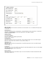
3.4.3 Streaming settings
These settings adjust the streaming mode, parameters and destinations.
BARIX AG | 28. Jan. 2014 | Configuration | Page 17/54
Annuncicom User Manual Version 4.07
Own Name
You can enter the name of the Annuncicom here. This name will be returned when using the DISCOVER
command (see technical documentation)
Default setting is "".
Streaming mode
"send always" will stream always
"send on TALK" will stream if the TALK button (command) is pressed
"send on Level" will stream if the incoming audio signal is above the Trigger level
"auto answer" will stream back for the Post Trigger Play duration after a stream has been received
"receive only" can receive a stream but will never send one
Default setting is "send on TALK".
Trigger level
Is only used when Streaming mode is "on Level".
Set to a value between 0 and 32767.
Open the Device status page and look for the Input peak value to get a hint for the trigger.
Default setting is "1000".
Pre Trigger Start
Pre Trigger Start can be adjusted to prevent cut offs when audio should be sent earlier than detected. It
defines the duration of the stream used before the actual trigger occurred.
This feature is normally used in combination with the send on level feature.
However, this parameter has a further use, to determine the receive stream strategy.
If 0, a minimum audio delay strategy is chosen at the receive side. Otherwise a minimum audio loss strategy
is chosen.
Default setting is "0" milliseconds.
Post Trigger Play
Post Trigger Play can be adjusted to prevent cut offs when audio should be sent longer than detected. It
defines the amount of time that the device will continue streaming after the actual trigger has been cleared.
This feature is normally used with the send on level feature. When Streaming mode is set to "auto answer"
this defines the duration the device will stream back after a stream has been received.
Default setting is "0" milliseconds.
Buffer Underrun Mode (TCP)
The Buffer Underrun Mode (TCP) defines the action if a TCP stream is slower than the real stream from the
encoder. In this case the output streaming buffer underruns and cannot hold older data anymore. The device
can then "disconnect" the TCP connection or it can "skip" the stream directly to the encoder stream without
disconnecting TCP.
Default setting is "disconnect".
Background Stream TCP Flow Control
The Background Stream TCP Flow Control defines data receiving strategy of stream interrupted by a priority
stream (so called background stream). If a priority stream is played, data in original stream can be either
accepted and thrown away or the TCP connection can be stopped.
Use throw away data if your streaming source is streaming in real time (e.g. Annuncicom). Use stop stream
when the streaming source is sending data as fast as possible (e.g. when sending a file from a PC).
This setting is only for receiving data and does not affect UDP streams.
BARIX AG | 28. Jan. 2014 | Configuration | Page 18/54
Annuncicom User Manual Version 4.07
Streaming Strategy
The Streaming Strategy defines how a packet is built and sent. On "lowest latency" the encoded data will be
sent directly after the encoding. On "optimal package" the packet will be filled up before sending.
Default setting is "lowest latency".
Non MP3 Packet Size
The Non MP3 Packet Size defines with how many bytes a non MP3 packet will be filled up before it is sent.
Set to a value between 1 and 1200.
Default setting is "1200".
Play Buffer
Defines the amount of bytes that will be stored before playing the received stream. Lower this value to
minimize delay, increase this value to prevent dropouts.
Default setting is "4096" Bytes.
Receive Timeout
Defines the amount of time between the end of a received stream and switching to being able to send.
Default setting is "200" msec.
TCP Priority Rx Port
Enter the port number for receiving a priority TCP stream. This stream always takes precedence.
Set to a value between 0 (disabled) and 65535.
Default port is "0".
UDP Priority Rx Port
Enter the port number for receiving a priority UDP stream. This stream always takes precedence.
Set to a value between 0 (disabled) and 65535.
Default port is "0".
Priority Message Minimum Volume
This is the guaranteed minimum volume for the priority message (received through UDP or TCP Priority
Streaming Listen Port). If the current volume is less than this and priority message begins, the volume is set
to this volume and reset back to original value when the message ends.
Default: "25%".
UDP Receiver Port
Enter the port number for receiving a UDP stream.
Set to a value between 0 (disabled) and 65535.
Default port for UDP is "3030".
UDP Tx Source Port
This setting is only used when working with a custom software application. Enter the source port number to
be used when sending a UDP stream. Set to a value between 0 and 65535. When set to 0 the port defined in
the Stream table destination entry is taken. Or if Stream destination is set to "origin source" then the UDP
Receiver Port is used.
Default setting is "0".
Radio Path
Enter a radio path to listen to the transmitted stream of this Barix Annuncicom using a device that is able to
play MP3 radio stations (also PC software like WinAmp).
The URL to connect is http://x.x.x.x/p. Where x.x.x.x is the IP address of this device and /p is this Radio
path.
Example: http://192.168.0.24/xstream
The device can serve up to 6 radio streams.
Default setting is "/xstream".
BARIX AG | 28. Jan. 2014 | Configuration | Page 19/54
Annuncicom User Manual Version 4.07
Relay While Audio
Activate relay when sound is coming out of the analog output and deactivate when not.
Default setting is "OFF".
Stream
There are two ways streaming can be set up:
1) Automatically by responding to the last calling station
(to the device from where the last communication came, viz. "to the origin source").
2) By means of Tables containing IP addressing information.
Refer to section 3.5 Table Settings for information on configuring tables.
Choose if the stream should be sent to the defined entries in the table or "to the origin source".
Current Table
There are 8 tables available, each with 8 entries. Only one table is in use at any particular time.
This parameter shows the current table selected over the remote command interface or the home page.
Multicast Address
Enter a Multicast address on which to receive an audio stream. As receive port the "UDP Receiver Port" is
taken. At start up the device will join the multicast group by periodically issuing IGMP join group messages.
Default setting is no address set, "0.0.0.0".
3.4.4 I/O Settings
These settings adjust the device behaviour for startup, inputs and outputs (attached buttons, the serial CTS
signal and the relay pulse duration).
Command Broadcasting
This option is for backward compatibility with firmware versions prior to 1.16. If you want "r=c=" commands
to be broadcast (UDP broadcast), set to compatibility mode. Otherwise choose secure mode, then "r=c="
commands will be sent only if stream to origin source is set and the origin source is known (command will be
sent to the last partner).
BARIX AG | 28. Jan. 2014 | Configuration | Page 20/54
Annuncicom User Manual Version 4.07
Init Sequence
This command sequence is always executed immediately after startup (see further below for commands).
Default: ""
I0 pushed command
Configure which command should be issued when the I0 button is pushed (see further below for commands).
Default: "c=83"
I0 released command
Configure which command should be issued when the I0 button is released (see further below for
commands).
Default: "c=84".
I1 pushed command
Configure which command should be issued when the I0 button is pushed (see further below for commands).
Default: "r=c=78"
I1 released command
Configure which command should be issued when the I0 button is released (see further below for
commands).
Default: "r=c=79"
Relay pulse duration
Defines the amount of time (in tenths of a second) the door strike will buzz when the "Dout" pulse command
is received.
Default: "30" (3 seconds)
CTS close command
Configures which command is issued when the CTS signal on the serial connector is activated (see further
information below in the command description).
Default: "r=c=78"
CTS open command
Configures which command is issued when the CTS signal on the serial connector is deactivated (see further
information below in the command description).
Default: "r=c=79"
RTS pulse duration
Defines the RTS pulse duration (in tenths of a second) when the "RTS" pulse command is received.
Default: "0".
BARIX AG | 28. Jan. 2014 | Configuration | Page 21/54
Annuncicom User Manual Version 4.07
Commands
Multiple commands can be added using the & character. They will be executed sequentially in the order that
they appear in the configuration field.
TALKING MODE
c=83 : Activate the talking mode
c=84 : Deactivate the talking mode
c=91 : Activate the forced talking mode
STREAMING
c=77 : Set destination Syntax : c=77&entry=x&ip=a.b.c.d&port=p&type=t
For x use 1 to 8 (Streaming destination 1 to 8)
a.b.c.d is the IP address to stream to
p stands for the port number to be used
For t use 0 (not used), 1 (Raw UDP) or 2 (Raw TCP)
Example:
c=77&entry=2&ip=192.168.0.100&port=3030&type=1 sets the destination 2 to Raw UDP to IP 192.168.0.100
on port 3030
I/O
c=78 : Activate the relay
c=79 : Deactivate the relay
c=80 : Pulse the relay for the preset time
c=85 : Simulate the I0 button being pressed
c=86 : Simulate the I0 button being released
c=87 : Simulate the I1 button being pressed
c=88 : Simulate the I1 button being released
SERIAL
c=89 : Simulates the CTS Signal being activated
c=90 : Simulates the CTS Signal being deactivated
c=60 : Activates the RTS Signal
c=61 : Deactivates the RTS Signal
REMOTE COMMANDS
r=x : send the command x to the last calling station remotely
r=a.b.c.d:p/x : send the command x, using UDP, to the remote IP a.b.c.d on the optional port p. Default if no
port is defined is the configured UDP command port.
Example:
r=192.168.0.99:12301/c=83 (sets the remote station to talking mode)
For further commands refer to the technical documentation available on www.barix.com.
BARIX AG | 28. Jan. 2014 | Configuration | Page 22/54
Annuncicom User Manual Version 4.07
3.4.5 Serial settings
These settings adjust the serial interface and serial gateway properties.
Baud rate
Select the serial transmission speed ("300" to "115200" Baud).
Default: "9600"
Data bits
Select "7" or "8" data bits.
Default: "8"
Parity
Select "no", "even" or "odd" parity.
Default: "no"
Stop bits
Select "1" or "2" stop bits.
Default: "1"
BARIX AG | 28. Jan. 2014 | Configuration | Page 23/54
Annuncicom User Manual Version 4.07
Handshake
Select the type of handshake:
Note: on ports supporting only RS485, the Handshake should be set to: "RS485 direction control"
RTS/CTS lines not used: "none"
RS232/RS422: "Software flow control(XON/XOFF)" or "Hardware flow control (RTS/CTS)"
RS485: "RS485 direction control"
Note: on ports supporting only RS485, make sure the Handshake is set to: "RS485 direction control"
Default: "none" for Serial 1, "RS45 direction control" for Serial 2
Local port
Defines the network port on which the serial interface can be accessed for the gateway application. Only
when "Local port" is set to "0" the serial interface can be used as a command interface.
If the serial gateway is enabled (Destination IP defined) and the "Local port" is set then this will be the source
port of the TCP connection. On "0" a random source port is used.
Default: "12303"
Destination IP
To have this device actively establish a serial gateway select the destination IP address of the partner device.
Select "0.0.0.0" when the serial interface is only used locally.
Default: "0.0.0.0" (disabled)
Destination port
Defines the port for the active serial gateway function (see destination IP).
Default: "0" (disabled)
Notes
Both settings, "Destination IP" and "Destination port" have to be set to enable the gateway function.
Serial 2
Local port
Defines the network port on which the 2nd serial interface can be accessed for the serial gateway application.
Default: "12304"
Destination IP
To have this device actively establish a serial gateway for serial port 2, select the destination IP address of
the partner device.
Select "0.0.0.0" to disable.
Default: "0.0.0.0" (disabled)
Destination port
Defines the port for the active serial gateway function for serial port 2 (see destination IP).
Default: "0" (disabled)
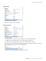
3.4.6 Control and SNMP settings
The Annuncicom provides two remote command interfaces: UDP and TCP. See the Technical Documentation
for more details about the protocol.
UDP Command Port
Configure a port number between 1 and 65535 to enable the UDP command interface.
Enter 0 to disable the UDP command interface.
Default: "12301"
TCP Command Port
Configure a port number between 1 and 65535 to enable the TCP command interface.
Enter 0 to disable the TCP command interface.
Default: "12302"
BARIX AG | 28. Jan. 2014 | Configuration | Page 24/54
Annuncicom User Manual Version 4.07
Web server port
Defines the port where the webserver of the device can be reached. If set to "0" the default HTTP port (80) is
used. Default: "0"
Serial Interface 1
Define the functionality of the 1st serial interface. "Command Interface" means the interface is used to input
commands. "Keypad" disables the serial command interface and supports a keypad.
Default: "Command Interface"
SNMP SETTINGS
Trap Target IP Address
Enter the IP address of the SNMP trap destination.
Default setting is "0.0.0.0".
Low Audio Level
Define the low audio level for the trap generation. A trap will be generated as soon as the audio level goes
below this value (and the silence timeout is run out). Default setting is "0".
High Audio Level
Define the high audio level for the trap generation. A trap will be generated as soon as the audio level goes
above this value.
Default setting is "0".
Trap Repeat
Define the repeat interval for the SNMP trap sending. The trap will be repeated if the values are still according
to the defined trap stages after this repeat time.
Default setting is "0".
Silence Timeout
Define the time that has to run out before a trap is sent when the audio level is below the defined low audio
value. Default setting is "0".
BARIX AG | 28. Jan. 2014 | Configuration | Page 25/54
Annuncicom User Manual Version 4.07
3.4.7 Security settings
These settings are used to secure access to the device on different levels. The status is shown next to each
password ("set" or "not set"). Access is unrestricted for levels without a password (default setting).
Save Configuration
Enter up to 24 characters to protect updates to the device configuration (Clicking the "Apply" button). Without
a valid password the device configuration can not be saved!
Enter 25 characters to erase the current password.
Default: "not set"
Save configuration password usage
When the password is set the user has to type in the password in the "Save Config Password field" before
hitting the "Apply" button. Without a valid password a warning will be displayed and the changes are not
saved.
View Configuration
Enter up to 24 characters to protect viewing the device configuration (Clicking the "Config" button). Without a
valid password the device configuration can not be viewed!
Enter 25 characters to erase the current password.
Default: "not set"
View configuration password usage
When the password is set login in using the the pop up window (the user name does not matter).
Only one user can log in at a time. Further attempts will be refused.
To log out click on the "Logout" link
Please widen the device window if the "Logout" link is not visible.
BARIX AG | 28. Jan. 2014 | Configuration | Page 26/54
Annuncicom User Manual Version 4.07
Control / Command
Enter up to 24 characters to secure the access to all control and command interfaces (WEB/CGI, Serial, TCP,
and UDP). Without a valid password the device can not be controlled.
Enter 25 characters to erase the current password.
Default: "not set"
Note
This security option should be used very carefully and is intended for advanced users only. Since the CGI
commands used in the web interface do not make use of passwords, setting this password would disable
any control of the device using a browser.
Level 4 to 6 (User)
Enter up to 24 characters to secure the access to customized web pages in 3 levels. Intended for advanced
users only, for details see the Technical Documentation. Without a valid password these user web pages
cannot be viewed.
Enter 25 characters to erase the current password.
Default: "not set"
Listening
Choose which level is used for preventing unauthorized listeners from listening to Annuncicom as Internet
Radio, or "not protected" for access for all.
SNMP Community RWrite
Choose a password for the Read and Write Community, or "not protected" to ignore both the read and write
communities or "no write access"
SNMP Community Read
Choose a password for the Read Community, or "not protected" to ignore the read community or "no
access"
Note that the Community RWrite setting takes priority.This means that if the Community RWrite is set to not
protected, Community Read is ignored.
BARIX AG | 28. Jan. 2014 | Configuration | Page 27/54
Annuncicom User Manual Version 4.07
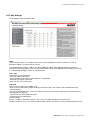
3.5 Table Settings
These settings adjust the table entries.
Table
Up to 8 entries can be set in a table. Each entry can be configured to stream to a device, a multi- or
broadcast address or to be a listener (server).
The numbered links (Table 1, Table 2 etc.) allow additional tables to be configured which can then be
selected via the home page or over the command interface. Only the configured Current Table (see section
3.4.3 Streaming settings) is active at a particular time.
Conn. type
Choose the type of connection:
"not used" for unused entries
"Internet Radio" for an internet radio station (1 user) (default)
"Raw UDP" for a UDP connection
"Raw TCP" for a TCP connection
IP # # # #
Enter 4 values of the entry IP address e.g.:
"0.0.0.0" for unused entries (except when the connection type is set to UDP it will be broadcasted e.g.
"192.168.0.255")
"0.0.0.0" for connection TCP + Port if this device is used as a TCP listener waiting for a connection from a
streaming device. (default)
"192.168.0.34" for a directed connection
"192.168.0.255" for a broadcast
Default settings:
Entry # 1 in table 1"Raw UDP 0.0.0.0:0". This means it is UDP broadcasting on port 3030!
All other entries are set to "not used" except for table 1 where all entries are set to "Internet Radio 0.0.0.0:0".
BARIX AG | 28. Jan. 2014 | Configuration | Page 28/54
Annuncicom User Manual Version 4.07
Port #
Enter the port number for each entry (between "0" and "65535"). If this port is set to "0" then the default ports
are used (Internet Radio "80", TCP "2020", UDP "UDP Receiver Port" or if "0" then "3030").
Default setting is "0".
Notes
The choice of settings to distribute the stream to the other station(s) depends on your environment and
desired functionality.
If the reception of up to 8 streams need to be guaranteed we recommend using TCP since lost packets are
retransmitted automatically.
If the stream is intended to be received by many devices we recommend using UDP broadcast (as long as all
devices are on the LAN as broadcast is not passed over a WAN by the routers).
If your network infrastructure is capable of multicasting use multicast to reduce the traffic generated by
broadcasting.
A mix of all the above is possible as each of the 8 destinations allow an individual choice of connection type.
BARIX AG | 28. Jan. 2014 | Configuration | Page 29/54
Annuncicom User Manual Version 4.07
4 Reverting to factory defaults
Click on the DEFAULTS button to enter the defaults page.
You will see the following screen:
Click on "Factory defaults" to revert all settings except "Network configuration" to factory defaults.
While restarting the device the following screen appears showing a number counting down:
Upon start up the following screen appears stating the successful reverting to factory defaults:
Hard default settings
To revert all settings (including the network settings) to factory defaults the Reset button has to be pressed
for about 5 seconds while the Annuncicom is powered.
Important note
Use this method if a connection to the Annuncicom cannot be established. This can happen if you have set a
Static IP address once, switched off Sonic IP and then forgotten the IP address.
The Hard default settings sets the IP Address to automatic discovery (0.0.0.0) and enables SonicIP.
If this fails we recommend downloading the Annuncicom Rescue Kit from www.barix.com.
Unzip the Kit and read "readme1st.txt" for instructions.
This Rescue Kit reloads the entire firmware, resets the device to factory default settings using the supplied
serial cross cable and a PC running W2K or XP.
BARIX AG | 28. Jan. 2014 | Reverting to factory defaults | Page 30/54
Annuncicom User Manual Version 4.07
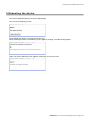
5 Rebooting the device
Click on the REBOOT button to enter the reboot page.
You will see the following screen:
Click "Reboot the device" to restart the Annuncicom.
While restarting the device the following screen appears showing a number counting down:
Upon start up the following screen appears stating the successful restart:
BARIX AG | 28. Jan. 2014 | Rebooting the device | Page 31/54
Annuncicom User Manual Version 4.07
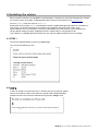
6 Updating the device
Barix constantly enhances the capabilities of their products. Therefore we recommend keeping the software
on the Annuncicom up-to-date. To download the latest firmware version please visit www.barix.com.
Click on downloads and then click on Annuncicom.
Scroll down to the section Firmware. Download the firmware update package and unpack to a local drive. If
your device can not be reached over the network using a browser the Rescue Kit can be used.
Read "readme1st.txt" for instructions. This Rescue Kit reloads the entire firmware, resets the device to
factory default settings using the supplied serial cross cable and a PC running W2K or XP.
If your device is reachable by browser follow the next steps to update the device over the network.
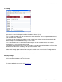
6.1 STEP 1
Click on the UPDATE button to enter the update page.
You will see the following screen:
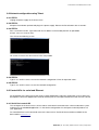
6.2 STEP 2
In order to upload a new firmware click on "Please click here to start the update".
After a count-down the device will restart in a special mode called Bootloader.
Please note that in this mode the standard HTTP port 80 is always used.
BARIX AG | 28. Jan. 2014 | Updating the device | Page 32/54
Annuncicom User Manual Version 4.07
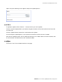
Upon start up the following screen appears ready for the update process.
6.3 STEP 3
To upload an update click on "Browse..." to locate the file you want to update.
The file is named compound.bin If you load the wrong file the device will not work and then the Rescue Kit
must be used.
Click the "Upload" button and wait for a confirmation of the upload.
Do not interrupt the upload process, reset or power off the device until the firmware is loaded.
After the file completely loads, click on update and then press the "reboot" button to restart the device with
the new firmware. The device takes a few seconds to reboot.
6.4 STEP 4
Click on the “here” link to reload the devices main page.
BARIX AG | 28. Jan. 2014 | Updating the device | Page 33/54
Annuncicom User Manual Version 4.07
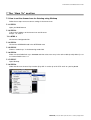
7 The “How To” section
7.1 How to set the Annuncicom for listening using WinAmp
Follow these steps to ensure correct settings in the Annuncicom.
7.1.1 STEP 1
Open your Web Browser
7.1.2 STEP 2
Type in the IP address of the Annuncicom and hit enter.
Example: 192.168.0.12
7.1.3 STEP 3
Click on the Configuration link.
7.1.4 STEP 4
Click on the STREAMING tab in the SETTINGS menu
7.1.5 STEP 5
Choose "send always" in the Streaming mode field.
7.1.6 STEP 6
Make sure that Radio Path says: /xstream and that at least one entry in the active table (usually table 1) is set
to “Internet Radio 0.0.0.0 : 0"
7.1.7 STEP 7
Open WinAmp
7.1.8 STEP 8
Under the file menu choose Play Location (Play URL in version 5) or hit CTRL and L on your keyboard.
BARIX AG | 28. Jan. 2014 | The “How To” section | Page 34/54
Annuncicom User Manual Version 4.07
7.1.9 STEP 9
Enter the IP address of your Annuncicom followed by /xstream.
Example: 192.168.0.12/xstream
Hit the Open button.
7.1.10 STEP 10
WinAmp will open the stream and buffer it. Wait a few seconds (to fill the buffer) before you can hear the input
signal in WinAmp.
7.1.11 NOTE
Once this works you can also try to set the Streaming mode to "send on TALK/CTS". Every time TALK is
activated WinAmp will start playing.
Also test the impact of different Quality and Sampling frequency settings. Play with the Buffer settings in
WinAmp to reduce dropouts or minimize delays.
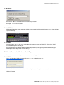
7.2 How to listen using Windows Media Player
Follow the steps 1 to 6 in chapter 8.1 to ensure correct settings in the Annuncicom.
7.2.1 STEP 1
Open your Windows Media Player and click on Open URL under the menu File.
Enter the IP address of your Annuncicom followed by /xstream. Example: 192.168.0.5/xstream
Hit the OK button.
BARIX AG | 28. Jan. 2014 | The “How To” section | Page 35/54
Annuncicom User Manual Version 4.07
7.2.2 STEP 2
The Media Player will open the stream and connect to the Annucicom. This is indicated by a single “)” going
from left to right and back in the stream bar on the bottom right.
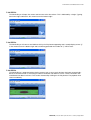
7.2.3 STEP 3
The Media Player will connect and indicate this by the Play button appearing and a steady display of two “))”
in the stream bar on the bottom right and as buffering proceeds the number of ”)” will increase.
7.2.4 STEP 4
The Media Player is programmed for playing streams from a server and calculates the buffer automatically.
Because the Annuncicom is streaming in real-time the buffer calculation assumes a slow connection and
would buffer for about 2 minutes. This can be shortened by clicking on the Play button. The playback then
starts immediately.
BARIX AG | 28. Jan. 2014 | The “How To” section | Page 36/54
Annuncicom User Manual Version 4.07
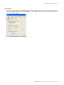
7.2.5 STEP 5
If you think that the delay is too be big the Media Player can be tuned to shorten it. Change the setting in the
Performance Tab (under the menu Tools/Options) as shown below and make sure that you click on Play as
soon as the button appears.
BARIX AG | 28. Jan. 2014 | The “How To” section | Page 37/54
Annuncicom User Manual Version 4.07
8 Application notes
This section will show you how to set the Annuncicom devices in common applications.
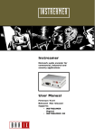
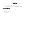
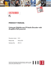
8.1 Two station intercom
Situation: two stations with one TALK button each.
Annuncicom’s default settings are already configured to allow two station intercom with only a few changes.
Station 1
192.168.0.10
LAN
Intercom
Panel with one
button
Station 2
192.168.0.20
Intercom
Panel with one
button
8.1.1 Station 1 configuration
Wiring
Station 1 is connected to an intercom panel:
Speaker to speaker out (C).
Microphone to Microphone In (E or F).
The TALK button to Input 0 (B1 and B3).
Network settings
If you have a DHCP Server in your network the device will automatically get an IP address and no changes
are needed.
Skip this step and go to Audio settings.
Use the following settings if you prefer to have a Static IP or if no DHCP server is available.
SonicIP is disabled; no need to hear it on power up as the IP Address is static and known and the device will
stay powered most of the time.
BARIX AG | 28. Jan. 2014 | Application notes | Page 38/54
Annuncicom User Manual Version 4.07
Audio settings
Change the Input source to "Mic".
The Microphone Gain as well as the Volume might need adjustment later on depending on the microphone
and speaker used.
Quality and Sampling frequency settings can be decreased to lower the network traffic but this will increase
the playback delay.
Streaming settings
No changes needed.
Streaming mode is set to talk when the TALK command is activated (i.e. TALK button pressed).
Post Trigger Play is set to talk on for 1 second after the button has been released. This prevents cut offs.
When receiving a stream, 4096 Bytes will be buffered first before playing it back over the speaker. Lower this
value to minimize delay, increase this value to prevent dropouts.
The stream will be transmitted using a UDP broadcast on port 3030.
BARIX AG | 28. Jan. 2014 | Application notes | Page 39/54
Annuncicom User Manual Version 4.07
IO settings
No changes needed.
The I0 pushed command c=83 will activate the TALK mode when the TALK button is pressed.
The I0 released command c=84 will deactivate the TALK mode when the TALK button is released.
Security settings
These settings need not to be changed for now.
Adjust them later according to your security needs.
Adjustments for Station 1 are completed.
8.1.2 Station 2 configuration
Wiring
Station 2 is connected to an Intercom panel:
Speaker to speaker out (C).
Microphone to Microphone In (E or F).
The TALK button to Input 0 (B1 and B3).
Network settings
If you have a DHCP Server in your network the device will automatically get an IP address and no changes
are needed.
Skip this step and go to Audio settings.
Use the following settings if you prefer to have a Static IP or if no DHCP server is available.
SonicIP is disabled; no need to hear it on power up as the IP Address is static and known and the device will
stay powered most of the time.
BARIX AG | 28. Jan. 2014 | Application notes | Page 40/54
Annuncicom User Manual Version 4.07
Audio settings
Change the Input source to "Mic".
The Microphone Gain as well as the Volume might need adjustment later on depending on the microphone
and speaker used.
Quality and Sampling frequency settings can be increased to lower the playback delay but this will slightly
increase network traffic.
Streaming settings
No changes needed.
See details under Station 1 configuration.
IO settings
No changes needed.
See details under Station 1 configuration.
Security settings
These settings need not to be changed for now.
Adjust them later according to your security needs.
BARIX AG | 28. Jan. 2014 | Application notes | Page 41/54
Annuncicom User Manual Version 4.07
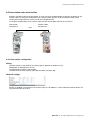
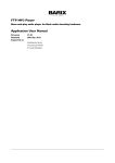
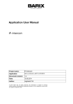
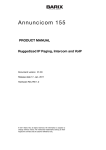
8.2 Door station and control station
Situation: one door and one control station. A visitor can push the RING button to activate the buzzer on the
control station. Pushing the TALK button on the control station permits to talk to the door station. When
releasing the TALK button the visitor can talk for a predefined time.
Pushing the DOOR button on the control station will activate the door strike to let the visitor in.
Door station
192.168.0.10
LAN
Control station
192.168.0.20
8.2.1 Door station configuration
Wiring
The door station is connected to an intercom panel: Speaker to speaker out (C).
Microphone to Microphone In (E or F).
The RING button to Input 1 (B2 and B3).
The door strike to Relay normally open (B4) and Relay common (B5).
Network settings
SonicIP is disabled; no need to hear it on power up as the IP Address is static and known and the device will
stay powered most of the time.
BARIX AG | 28. Jan. 2014 | Application notes | Page 42/54
Annuncicom User Manual Version 4.07
Audio settings
Change the Input source to "Mic".
The Microphone Gain might need adjustment later on depending on the used microphone.
Same goes for Volume depending on the speaker.
Quality and Sampling frequency settings can be increased to lower the playback delay but this will increase
network traffic slightly.
Streaming settings
The door station is set to auto answer for 12 seconds (Post Trigger Play) using UDP broadcast.
When receiving a stream, 4096 Bytes will be buffered first before playing it back over the speaker. Lower this
value to minimize delay, increase this value to prevent dropouts.
The stream will be transmitted using a UDP broadcast on port 3030.
BARIX AG | 28. Jan. 2014 | Application notes | Page 43/54
Annuncicom User Manual Version 4.07
IO settings
The I1 pushed command r=192.168.0.20/c=80 will activate the relay on the control station for the Relay
toggle duration time set in the control station when the RING button is pressed on the door station panel.
The I1 released command has to be blank.
Adjust the Relay toggle duration according to the specification of the door strike used.
All other commands are not used and can be left blank or as is.
Security settings
These settings need not to be changed for now.
Adjust them later according to your security needs.
8.2.2 Control station configuration
Lets take a look on how to configure the control station.
Wiring
The control station is connected to an intercom panel: Speaker to speaker out (C).
Microphone to Microphone In (E or F).
The TALK button to Input 0 (B1 and B3).
The DOOR button to Input 1 (B2 and B3).
The flash or buzzer to Relay normally open (B4) and Relay common (B5).
Network settings
SonicIP is disabled, no need to hear it on power up as the IP is static and known and will not be power
cycled anyway.
BARIX AG | 28. Jan. 2014 | Application notes | Page 44/54
Annuncicom User Manual Version 4.07
Audio settings
Change the Input source to "Mic".
See details under Door station configuration.
Streaming settings
No changes needed.
The control station is set to talk only when the Talk button is pushed using UDP broadcast.
Pre Trigger Start can be adjusted to prevent cut offs when starting to talk too early.
Post Trigger Play can be adjusted to prevent cut offs after the button has been released.
When receiving a stream, 4096 Bytes will be buffered first before playing it back over the speaker. Lower this
value to minimize delay, increase this value to prevent dropouts.
The stream will be transmitted using a UDP broadcast on port 3030.
BARIX AG | 28. Jan. 2014 | Application notes | Page 45/54
Annuncicom User Manual Version 4.07
IO settings
The I0 pushed command c=83 will activate the TALKING mode in the control station when the Talk button is
pressed on the control station panel and deactivated when released (c=84).
The I1 pushed command r=c=78 will activate the relay on the door station and hence open the door strike as
long the DOOR button is pushed.
To prevent the door from being opened by pressing the door button without someone first pushing the Bell
button change the Command Broadcasting to “secure mode”
The I1 released command r=c=78 will deactivate the relay on the door station and hence lock the door.
Another way is to use a pulse command instead:
Change the I1 pushed command to r=c=80 and leave the I1 released command blank. Adjust the Relay pulse
duration on the other station according to the spec of the used door strike.
Adjust the Relay pulse duration according to your needs of the flash or buzzer duration. The setting 30 means
that the flash will light up (or the buzzer will sound) for 3 seconds when someone pushes the Ring button at
the door.
All other commands are not used and can be left blank or as is.
Security settings
These settings need not to be changed for now.
Adjust them later according to your security needs.
For further application notes please visit www.barix.com.
BARIX AG | 28. Jan. 2014 | Application notes | Page 46/54
Annuncicom User Manual Version 4.07
9 Advanced user section
9.1 Network configuration using serial cable supplied
9.1.1 STEP 1
Open a Terminal program.
9.1.2 STEP 2
Go to the settings menu and adjust the following settings: Baud rate 9600 bit/sec, 8 Data Bits, no Parity and
1 Stop Bit.
9.1.3 STEP 3
Unplug the power supply of the Annuncicom.
9.1.4 STEP 4
Connect the supplied serial cable to your PC’s COM port and to the serial port of the Annuncicom.
9.1.5 STEP 5
Keep the Reset button pushed and plug in the power supply. Release the Reset button as soon as you see
the following screen:
9.1.6 STEP 6
Hit <s> to skip network discovery if not connected to a network and the following screen appears:
9.1.7 STEP 7
Hit <s> to get to the Annuncicom setup.
BARIX AG | 28. Jan. 2014 | Advanced user section | Page 47/54
Annuncicom User Manual Version 4.07
9.1.8 STEP 8
Hit <enter> to enter the Annuncicom setup mode.
9.1.9 STEP 9
Type in <0> and hit <enter> to enter the Network configuration. Enter all requested values:
9.1.10 STEP 10
Type in <9> and hit <enter> to save the Network configuration.
BARIX AG | 28. Jan. 2014 | Advanced user section | Page 48/54
Annuncicom User Manual Version 4.07
9.2 Network configuration using Telnet
9.2.1 STEP 1
Unplug the power supply of the Annuncicom.
9.2.2 STEP 2
Keep the Reset button pushed and plug in the power supply. Release the Reset button after 5 seconds.
9.2.3 STEP 3
Run a command session. Type telnet with the IP address announced by SonicIP on port 9999.
Example: telnet 192.168.0.168 9999
You will see the following screen:
Hit <enter> to access the Annuncicom in the setup mode.
9.2.4 STEP 4
Type in <0> and hit <enter> to enter the Network configuration. Enter all requested values.
9.2.5 STEP 5
Type in <9> and hit <enter> to save the Network configuration.
9.3 Control APIs for serial and Ethernet
For integration of the Annuncicom into various control applications and home automation systems, Barix has
developed a control API (Application Protocol Interface) for the serial port and Ethernet UDP and TCP control.
9.3.1 Serial Port control API
The serial port on the Annuncicom can be used to send control commands from a home automation system
and other PC or embedded applications. In the device configuration the serial port can be adjusted to suit
your application.
For a detailed list of serial commands refer to the Annuncicom Technical Documentation available on the
Barix website www.barix.com
BARIX AG | 28. Jan. 2014 | Advanced user section | Page 49/54
Annuncicom User Manual Version 4.07
9.3.2 Ethernet UDP or TCP control commands
The same control commands used on the serial port can be used as UDP or TCP commands over Ethernet.
For more information and a detailed list of UDP and TCP control commands refer to the Annuncicom
Technical Documentation available on www.barix.com
9.4 Expert settings
There is also the possibility to disable some IP protocols. Change the IP address in the serial- , Telnet- or
Web configuration to:
0.0.1.0 to disable AutoIP
0.0.2.0 to disable BOOTP
0.0.4.0 to disable DHCP
0.0.8.0 to disable IPZator
The values can be combined for example, 0.0.12.0 turns of DHCP and IPZator.
BARIX AG | 28. Jan. 2014 | Advanced user section | Page 50/54
10 FAQ and Troubleshooting
Q: I don’t see any status lights on at all.
A: Make sure the power cable is correctly plugged into the unit and make sure the power supply is plugged
into the wall.
Q: Red status light is flashing red.
A: Make sure the network cable is plugged into the unit. The status light on the jack indicates if you are
connected to the network or not. Make sure the Music Server program is running on the network. You can
also ping the device to see if it’s on your network.
Q: How do I ping the Annuncicom to see if it’s on my network?
A: You can ping any device on your network by opening a DOS command box.
Type ping and the IP address of the unit to see if you can get a response.
Example: ping 192.168.2.10
The proper response would be to see the message “reply from 192.168.2.10”.
If you see the message “request timed out”, it means that the Annuncicom is not on your network or that you
have entered the wrong numbers for the IP address.
Q: When I type in the IP address into the browser I get a “This Page Cannot Be Displayed” Message
A: This means that you cannot connect to the Annuncicom. There could be a couple of different reasons.
Make sure you are typing in the IP address correctly. Check the cables to make sure the Annuncicom is
properly connected to the network.
Q: Will the Annuncicom work on my operating system?
A: The Annuncicom works on virtually any operating system, to control the Annuncicom a standard web
browser is all you need.
Q: How can I prevent delays during speech transaction ?
A: There is no clear recommendation! This is depending from the customer´s environment. But the delay is
adjustable by the parameters play buffer, encoding quality and sampling frequency. A poor sound/voice
quality will fill the default buffer slower than a good sound/voice quality. But note, a higher sound quality
causes also much more network traffic !
BARIX AG | 28. Jan. 2014 | FAQ and Troubleshooting | Page 51/54
Annuncicom User Manual Version 4.07
11 Dictionary
DHCP
Short for Dynamic Host Configuration Protocol, DHCP is a protocol used to assign an IP address to a device
connected to a Network.
DOS
Microsoft DOS (Disk Operating System) is a command line user interface. MS-DOS 1.0 was released in 1981
for IBM computers. While MS-DOS is not used commonly today, it still can be accessed from Windows 95,
XP, Windows 98 or Windows NT by clicking Start / Run and typing command or CMD in Windows 2000.
IP
Short for Internet Protocol, the IP is an address of a computer or other network device on a network using IP
or TCP/IP. Every device on an IP-based network requires an IP address to identify its location or address on
the network.
Example: 192.168.2.10
IPzator
Barix IPzator™ technology is designed for the purpose that the Annuncicom can create its own IP address
according to the network structure in case it can’t receive one from your network. If DHCP, AUTO IP or
BOOTP fail, IPzator will create an IP address within the subnet and test it. If the address works and is not
being used by another device on the network, it will give the address to the Annuncicom.
MAC address
Abbreviation for Medium Access Control, a MAC is a unique address number formatted in hexadecimal
format and given to each computer and/or network device on a computer network. Because a MAC address
is a unique address a computer network will not have the same MAC address assigned to more than one
computer or network device.
Example: A1:B2:C3:D4:E5:F6
Netmask
A number used to identify a sub network so that an IP address can be shared on a LAN (Local Area Network).
A mask is used to determine what subnet an IP address belongs to. An IP address has two components, the
network address and the host address. For example, consider the IP address 150.215.17.009. Assuming this
is part of a Class B network, the first two numbers (150.2) represent the Class B network address, and the
second two numbers (.017.009) identify a particular host on this network. The Netmask would then be
255.255.0.0
Ping
Ping is a basic Internet program that lets you verify that a particular IP address exists and can accept
requests. Example: ping 192.168.2.10
SonicIP
Barix SonicIP® technology is designed to vocally announce the Annuncicom’s current IP address. This makes
it easier and faster to obtain the necessary network information. To make use of SonicIP plug in the included
earphone into RCA audio out, connect the network and plug in the power supply. It will announce the address
over the earphones right after power up.
Static IP
A Static IP is a fixed IP address that you assign manually
to a device on the network. It remains valid until you disable it.
BARIX AG | 28. Jan. 2014 | Dictionary | Page 52/54
Annuncicom User Manual Version 4.07
Telnet
Telnet is a user command and an underlying TCP/IP protocol for accessing remote computers. On the Web,
HTTP and FTP protocols allow you to request specific files from remote computers, but not to actually be
logged on as a user of that computer. With Telnet, you log on as a regular user with whatever privileges you
may have been granted to the specific application and data on that computer.
Example: telnet 192.168.2.10
BARIX AG | 28. Jan. 2014 | Dictionary | Page 53/54
Annuncicom User Manual Version 4.07
12 Legal Information
© 2014 Barix AG, Zurich, Switzerland.
All rights reserved.
All information is subject to change without notice.
All mentioned trademarks belong to their respective owners and are used for reference only.
Barix, Annuncicom, SonicIP and IPzator are trademarks of Barix AG, Switzerland and are registered in certain
countries.
For information about our devices and the latest version of this manual please visit www.barix.com.
Barix AG
Seefeldstrasse 303
8008 Zurich
SWITZERLAND
Phone:
Fax:
+41 43 433 22 11
+41 44 274 28 49
Internet
web: www.barix.com
email: [email protected]
support:[email protected]
wiki:
wiki.barix.com
BARIX AG | 28. Jan. 2014 | Legal Information | Page 54/54