1
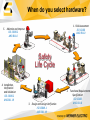
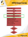
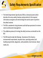
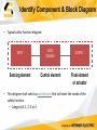
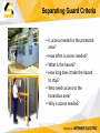
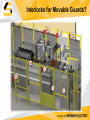
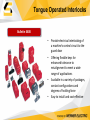
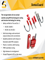
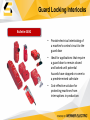
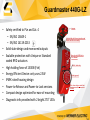
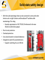
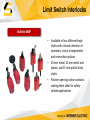
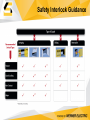
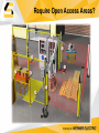
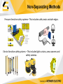
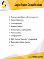
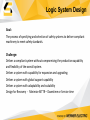
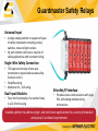
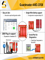
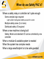
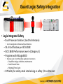
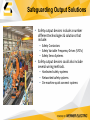
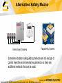
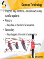
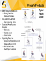
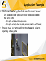
SF06
Machine Safety Solutions Overview
Welcome
During this session we will discuss various types of safety devices available for
machinery safety solutions to prevent access to or control a hazard.
We will include products from Rockwell Automation, Numatics and Paletti.
Additional discussion is available in these sessions:
• SF01 – Risk and Hazard Assessment
• SF02 – Introduction to ISO 13849
• SF04 – Guard Interlocking Update ref ISO 14119
• SF05 – Configurable Safety Relay Lab with 440R-CR30
Does it really matter which device?
A machine control strategy that includes both safety
and production control systems?
• Purpose of production system is to produce
• Purpose of safety system is to protect
In the past, safety and production control systems
shared little, if any information
Harmonizing your safety and production control
systems offer tremendous opportunities to improve
productivity
• Shared diagnostics on common HMI for faster
troubleshooting
• Safety system that changes parameters based on the
state of the production system
• Zone control to enable continued production flow
when one zone is shut down
• Better shut down and restart of production systems
after a safety event
Control
System
Operating
Equipment
Safety
System
When do you select hardware?
1. Risk Assessment
ISO 12100
ANSI B11.0
5. Maintain and Improve
ISO 13849-2
ANSI B11.0
Safety
Life Cycle
4. Installation,
Verification
and Validation
ISO 13849-2
ANSI B11.19
3. Design and Design Verification
ISO 13849-1
ANSI B11.19
2. Functional Requirements
Specification
ISO 12100
ANSI B11.0
Risk Assessment Overview
Determine the Limits of the Machinery
Hazard Identification
Risk Estimation
Risk Evaluation
Is the Risk
Reduced?
No
Measures for Risk Reduction
Refer to SF01 – Risk and Hazard Assessment for
more information on this process.
Yes
End
Risk Reduction Overview
Measures for Risk Reduction
1)
2)
3)
Inherently Safe Design
Safeguards & Complementary
Information for Use
Is a Control
System
Needed?
Yes
Design SRP/CS per ISO 13849-1:2006
Refer to SF01 – Risk and Hazard Assessment for
more information on this process.
No
Back to
Risk
Assessment
SRP/CS Design Overview
Identify the Safety Functions
Specify the Characteristics (SRS)
Required Performance Level (PLr)
Realization – Identify SRP/CS Components
Evaluate the Performance Level
1) Category/System Architecture
2) Mean Time to Dangerous Failure (MTTFd)
3) Diagnostic Coverage (DC)
4) Common Cause Failure (CCF)
5) Software (if existing)
Verification
Validation
Safety Requirements Specification
• The Safety Requirements Specification (SRS) is a formal document which
describes the various safety functions and provides all of the required
information an engineer will need to design the control system to perform
the safety functions.
• The SRS is considered a living document and shall have provisions for revision
control and document management.
• The validation protocols for testing the safety functions are derived from the
SRS.
• The SRS should include the following: Description of the function,
environmental requirements, response times, operating modes, fault
handling requirements, diagnostics, safe parameters, fault exclusion, failure
modes, etc.
Six Steps to Performance Level
Once the Safety Functions have been identified and defined, there are six basic
steps required to determine the Performance Level.
Step 1 – Determine the required performance level (PLr)
Step 2 – Identify the SRP/CS Components & Design Block Diagram
Step 3 – Evaluate the Performance Level (PL)
Step 3a - Category
Step 3b - Mean Time to Dangerous Failure (MTTFd)
Step 3c - Diagnostic Coverage (DC)
Step 3d - Common Cause Failure (CCF)
Step 4 – Develop Safety-Related Software (If Required)
Step 5 – Verification of Performance Level (PL > PLr)
Step 6 – Validation that all requirements are met
Performance Level Required
• The Risk Assessment determines the Performance Level required, PLr
• Creates the Foundation of the Safety System Functional Requirements,
System Design and Validation Protocol
• Shows “Due Diligence” and compliance to standards
Performance
Level, PLr
P1
F1
P2
S1
P1
Task/Hazard
a
Contribution to
Risk
Reduction
Low
b
F2
P2
P1
c
F1
P2
S2
P1
d
F2
P2
S = Severity
F = Frequency or Duration of Exposure
P = Avoidance Probability
e
High
Six Steps to Performance Level
Once the Safety Functions have been identified and defined, there are six basic
steps required to determine the Performance Level.
Step 1 – Determine the required performance level (PLr)
Step 2 – Identify the SRP/CS Components & Design Block Diagram
Step 3 – Evaluate the Performance Level (PL)
Step 3a - Category
Step 3b - Mean Time to Dangerous Failure (MTTFd)
Step 3c - Diagnostic Coverage (DC)
Step 3d - Common Cause Failure (CCF)
Step 4 – Develop Safety-Related Software (If Required)
Step 5 – Verification of Performance Level (PL > PLr)
Step 6 – Validation that all requirements are met
Identify Component & Block Diagram
• Typical safety function diagram:
INPUT
LOGIC
SOLVING
OUTPUT
Sensing element
Control element
Final element
or actuator
• The designer shall select an architecture that will meet the needs of the
safety function.
– Category B, 1, 2, 3 or 4
Risk Reduction Hierarchy
Design it out
Most
Effective
Fixed enclosing guard
Controlling, Limiting or
Monitoring Access
Awareness Means, Training and
Procedures (Administrative)
Personal protective equipment
Least
Effective
Design it out?
Mechanical and design engineers are integral to the safety process and often
the most capable to prevent a hazard.
Selection of technology
Is the technology/device inherently dangerous or safe?
Can an alternative technology be used?
Placement or orientation within the machine
Can the hazard be mitigated by redesign?
Physical characteristics
Can a hazard be mitigated through the design of parts?
Risk Reduction Hierarchy
Design it out
Most
Effective
Fixed enclosing guard
Controlling, Limiting or
Monitoring Access
Awareness Means, Training and
Procedures (Administrative)
Personal protective equipment
Least
Effective
Safeguard Requirements
• Prevent contact
– Prevent worker’s body or
clothing from contacting
hazardous moving parts
• Secure
– Safeguards are firmly secured
to machine and not easily
removed
(require use of tools)
• Protect from falling objects
– No objects can fall into moving
parts
Two Types of Guarding
• Separating
– Fixed fences & barriers
require a tool for removal
– Moveable guarding types
require interlock switches
• Non-Separating
– Mechanical detection devices
• Safety Mats
• Pressure Sensitive Edges
– Electro-Sensitive Devices
• Light Curtains
• Area Scanners
require safe distance
calculation
– Localized protection devices
• Emergency Stops
• Two Hand Control
– Moveable protection devices
• Enabling Switches
Separating Guarding Examples
Fixed Guarding
Separating guards provide a physical
separation from machine hazards
Moveable Guarding
Separating Guard Criteria
• Is access needed to the protected
area?
• How often is access needed?
• What is the hazard?
• How long does it take the hazard
to stop?
• Who needs access to the
hazardous area?
• Why is access needed?
Paletti Guarding Solutions
Interlocks for Movable Guards?
Tongue Operated Interlocks
Bulletin 440K
• Provide electrical interlocking of
a machine’s control circuit to the
guard door
• Offering flexible keys for
enhanced tolerance to
misalignment to meet a wide
range of applications
• Available in a variety of packages,
contact configurations and
degrees of holding force
• Easy to install and cost-effective
Non-Contact Interlocks
Bulletin 440N
• Requires no physical contact
with the actuator
• No contact between sensor
and actuator helps reduce risk
of debris contamination
• Large sensing field helps
compensate for door
misalignment
• Types: RFID coded (standard
& unique) and magnetically
coded
SensaGuard
The next generation of non contact
switches using RFID technology for coding
and inductive technology for sensing
• Safety certified to PLe and Cat. 4
• EN/ISO 13849-1
• EN/ISO 14119:2013
• Solid state design and monitored
outputs allows series connections
• Scalable protection with Unique or
Standard coded RFID actuators
• Plastic or stainless steel housing
• IP69K washdown rating
• High tolerance to misalignment
• Output/Diagnostic LED on the sensor
Guard Locking Interlocks
Bulletin 440G
• Provide electrical interlocking of
a machine’s control circuit to the
guard door
• Ideal for applications that require
a guard door to remain closed
and locked until potential
hazards have stopped or come to
a predetermined safe state
• Cost-effective solution for
protecting machines from
interruptions in production
Guardmaster 440G-LZ
• Safety certified to PLe and Cat. 4
– EN/ISO 13849-1
– EN/ISO 14119:2013
• Solid state design and monitored outputs
• Scalable protection with Unique or Standard
coded RFID actuators
• High holding force of 1300N (Fzh)
• Energy Efficient Device: only uses 2.5W
• IP69K-rated housing design
• Power-to-Release and Power-to-Lock versions
• Compact design optimized for ease of mounting
• Diagnostic info provided with 2 bright 270° LEDs
Actuator
Metal holding bolt (inserts into the metal
bracket and sensor assembly)
Bar code with URL link to
User Manual
LEDs (both sides)
Global approvals
Slim, clean design, sealed body
(IP69K)
Solid-state safety design
• With the solid state design these can be connected in series with other
devices such as Light Curtains and SensaGuard™ switches while
maintaining a PLe rating
– Exceeds requirements of ISO TR 24119 referenced in the new
EN/ISO 14119:2013 standard
• Short circuit protection
• Overload protection
• Cross fault (channel to channel) detection
• Designed to switch DC powered devices
– Supports switching of up to 200 mA
Hinge Operated Interlocks
Bulletin 440H
• Connect directly to a guard door
hinge and allow immediate
opening of the guard
• Provides good clearance due to
unobtrusive mounting
• Well-suited for machines where
product is loaded through a
hinged guard
• Ideal for machines with
misaligned guards or applications
with contaminants
Limit Switch Interlocks
Bulletin 440P
• Available in four different body
styles with a broad selection of
operators, circuit arrangements
and connection options
• 30 mm metal, 22 mm metal and
plastic, and 15 mm plastic body
styles
• Positive opening-action contacts,
making them ideal for safetyrelated applications
Safety Interlock Guidance
Require Open Access Areas?
Non-Separating Methods
Pressure Sensitive safety systems– This includes safety mats and safe edges.
Electro Sensitive safety systems – This includes light curtains, area scanners and
safety cameras.
Pressure Sensitive Devices
MatGuard™ Safety Mats
•
•
•
•
•
•
Specially hardened steel plate
construction
Active sensing over entire mat
surface
Four-wire system for fault detection
Minimum detection weight of 66 lbs
Variety of aluminum trim options
Special sizes and shapes are possible
IP67
Safedge™ Safety Edges
•
•
•
•
•
Conductive rubber profiles
5 mm, 19 mm or 41 mm (0.19 in.,
0.74 in. or 1.61 in.) cushion factors
available
50 m (164.04 ft.) maximum lengths
Variety of profile shapes
IP65
Light Curtains
GuardShield Type 4
•
•
•
•
Advanced features and functionality
Range: 16 m
Integrated laser alignment
Finger 14 mm or hand 30 mm
detection
• Cascadeable
• IP65 standard / IP67 kits available
Safe 4
•
•
•
•
ON/OFF functionality standard
Range: 9 m to 30 m
Integrated laser alignment
Finger 14 mm or hand 30 mm
detection
• IP65
NEW - SC300 Safety Camera
• Compact Safety Camera (Up to 2 meters)
• Expansion of safety light curtain portfolio
• One size fits all - solution
• No software needed
• Easy commissioning with teaching
• 24Vdc, 20ms response time, IP54
• Performance Level d (PLd ISO 13849)
• SIL 2 (IEC 61508)
• Type 3 (IEC 61496)
Presence Sensing Guidance
Other Non-Separating Devices
Localized safety systems such as emergency stop pushbuttons, pull-cords,
two hand control stations and emergency switching off devices
Movable safety systems such as enabling switches and pendants
NEW - MobileView
A new portable, tethered EOI device
• HMI Applications with line of sight
requirements
• Setup/calibration activities where
an operator needs to be in close
proximity to application with access
to HMI
• Applications requiring local safety
functionality through E-STOP or
enabling switch
• Maintenance applications
Identify Component & Block Diagram
• Typical safety function diagram:
INPUT
LOGIC
SOLVING
OUTPUT
Sensing element
Control element
Final element
or actuator
• The designer shall select an architecture that will meet the needs of the
safety function.
– Category B, 1, 2, 3 or 4
Logic System Considerations
1.
2.
3.
4.
5.
6.
7.
8.
9.
10.
Performance Level, Category or SIL level requirement
Functional Requirements
Control requirements
System size / footprint
System complexity – Logic Requirements
Process complexity
Zoning requirements
Safety Monitoring / Diagnostics / Information Needs
Documentation, Validation, Reporting
Cost
Logic System Design
Goal:
The process of specifying and selection of safety systems to deliver compliant
machinery to meet safety standards.
Challenge:
Deliver a compliant system without compromising the production capability
and flexibility of the overall system.
Deliver a system with capability for expansion and upgrading.
Deliver a system with global support capability
Deliver a system with adaptability and scalability
Design for Recovery - Minimize MTTR – Downtime or Service time
Guardmaster Safety Relays
Universal Input
•
•
A single catalog number to support all types
of safety components including e-stops,
switches, mats and light curtains
Six part numbers will cover a majority of
safety applications with consistent wiring
Single-Wire Safety Connection
•
•
•
TÜV approved concept of one-wire
connection to expand and cascade safety
functions to SIL3
Simplifies wiring
Maintains PLe , SIL3 rating
Dual Input Modules
•
EtherNet/IP Interface
•
Provides status communication with Logix
PAC, eliminating multiple wiring
terminations
Supports star, linear or DLR topologies
Twice the functionality of a standard relay
in a 22.5mm housing
• Reduced wiring for commissioning and
•
Scalable
tohave
address
and multi-zone applications for a variety of standard
multipleplatform
inputs can
logic singleconfigured
simply in a single relay
and special functional requirements
Guardmaster 440C-CR30
Safety made Simple & Flexible
• Supports four to nine dual channel input circuits and up to five safety output zones
• Flexible configuration allows you to re-engineer and rapidly integrate application without
having to incur high costs of rewiring
• Innovative safety logic editor reduces the friction involved in setting up a safety system by
minimizing manual input for a “best-in-class” configuration experience
Safety & Productivity
• Embedded serial port for direct diagnostic communications to PanelView
Component terminals or Micro800™ controllers
• 16 user configured status LEDs allow you to tailor indication to best suit your
application
Optimize Panel Space
• 22 Safety I/O in a compact 110mm wide housing
• Expand by up to 16 standard I/O using front mounted plug-in slots that allow
you to maintain the 110mm horizontal footprint
Part of the Connected Components Workbench™ Bundle
• Preferred compatibility within the bundle
• Reduced supply chain costs
• One software supports Guardmaster 440C-CR30, Micro800 controllers, PowerFlex®
drives, Kinetix™ 3 servo drives and PanelView™ Component terminals
Guardmaster 440C-CR30
• Single Wire Safety support:
• Easy to Use:
– Innovative rapid configuration editor
• 2080 Plug-in support:
– Expansion of standard I/O
Muting Sensors
Reset
Feedback Monitoring
– A single wire to expand safety I/O
• Serial Port for
Diagnostics
– PanelView Component or
Micro800
When do use Safety PAC’s?
Where a safety relay or controller isn’t quite enough
Some complex logic required
Light curtain muting plus enable pendant for a zone
Multiple safety zones (3 or more)
Distributed safety I/O required
Where a new machine is being built
Safety, Motion and standard I/O can be controlled by one
controller
When a modular & scalable system is needed
When the system has complex needs
When a large area/footprint is to be safe-guarded
GuardLogix Safety Integration
• Logix Integrated Safety
– Dual Processor Solution (1oo2 Architecture)
• 1oo2 is recognized as the best safety architecture
– SIL-3 Certification per IEC 61508
– ISO 13849 Performance Level e (Category 4)
– Programs with RSLogix5000
• Extensive suite of certified safety application instructions
– Simplifies design, validation, maintenance
– Dual Channel Suite
– Muting & Press Suite
– CIP Safety for safety rated interlocking or safety I/O on Ethernet
Output Device Considerations
1.
2.
3.
4.
5.
6.
7.
8.
9.
10.
What type of device needs to be isolated?
What type of power needs to be isolated?
What is the current requirements of the output device?
Where are the outputs located?
Is speed control needed?
Is position control needed?
Is signal control needed?
Hardwired or network control?
On-machine quick disconect solution?
Cost
Safeguarding Output Solutions
• Safety output devices include a number
different technologies & solutions that
include:
– Safety Contactors
– Safety Variable Frequency Drives (VFD’s)
– Safety Servo Systems
• Safety output devices could also include
several wiring methods.
– Hardwired safety systems
– Networked safety systems
– On-machine quick connect systems
Safety actuators/output devices
Safety
Contactors
PowerFlex
AC drives
Kinetix
Servo drives
• Mechanically linked,
positively guided and
Mirrored contacts
• Feedback circuit for
safety integrity
• Range of power ratings
• PowerFlex AC drives
with optional integrated
safety functions
• Advanced safety
functions in PowerFlex
750 series AC drives
• May replace the need
for safety contactors
• Remove torque without
powering down machine
• Restart machines faster
• Kinetix 6000 with
optional integrated
safety functions
• Safe Torque Off and
advanced safety
• Remove torque without
powering down machine
• Restart machines faster
Pneumatic and Hydraulic Systems
These valves meet Cat3
and Cat4 requirements and
are used in safety solutions
to control pneumatic &
hydraulic hazards.
Numaitcs Zone Safety
Series 503 valves with G3 communications
Numatics Zone Safety
https://www.youtube.com/watch?v=-x4TQVU20eI
You can see this technology at work in
booths 705 and 804 in the tradeshow area.
Questions
???
Alternative Safety Means
ElectroGuard Systems
Trapped Key Systems
Sometimes tradition safeguarding methods are not enough or
cannot meet the environmental requirements so there are
additional methods that can be used.
ElectroGuard System Description
& Uses
What is an ElectroGuard system? It is a energy control and isolation solution that provides a
systematic method of control.
An ElectroGuard system uses safety rated contactors, safety
rated pneumatic valves and safety rated hydraulic valves to
isolate the energy sources. Pressure switches and voltage
meters are used to verify that the energy sources have been
removed and safety relays to verify that the correct actions
have been taken.
Where do you use ElectroGuard systems?
ElectroGuard systems are used in areas where lock-out & tagout are complex, spread out, distributed or takes multiple steps.
Trapped Key System Description &
Uses
What is a trapped key system? It is a safety solution that uses keys to ensure a that
energy sources and access points are isolated prior to access.
The trapped key system uses a sequence of captive keys,
switches, valves, interlock devices and simple control
solutions to isolate energy sources.
How do trapped key systems work?
Trapped systems use keys that are captive when the
isolation device is in the on position. Keys can only be
removed when hazardous energy is removed.
How can trapped key solutions handle complex system requirements?
Trapped key solutions use a building block approach.
Common Terminology
• Trapped Key Interlock – also known as key
transfer systems
• Primary
– Keys free at the start of a sequence
• Secondary
– Keys trapped at the start of a sequence
• Personal key
Secondary
Keys
Primary
Key
Secondary/
Personal
Key
– Secondary key to be released and carried by
the person into the hazard
Primary
Key
Primary
Key
Copyright © 2012 Rockwell Automation, Inc. All rights reserved.
60
Prosafe Products
• Start Sequence Devices
Start Sequence Devices
Typical
Prosafe
System
– Rotary Switches
– Solenoid Release
• Key Control Element
– Key Exchange Units
• Guarded Area Access
Devices
– Bolt Lock
– Access Locks
– Slam Locks
Key Control Element
Guarded Area
Access Devices
• Specialty Devices
–
–
–
–
Electronic Timed Delay Unit
Stopped Motion Unit
Mini Valve Locks
Switchgear Adaptors
Copyright © 2012 Rockwell Automation, Inc. All rights reserved.
61
61
Application Example
• Customer has two gates that need to be accessed
– On occasion, both gates will need to be accessed at
the same time
• One gate will allow full-body access
• One gate will only allow top body access (reach in with hands)
• Power must be removed from the hazards prior to
opening either gate
Copyright © 2012 Rockwell Automation, Inc. All rights reserved.
62