1
363-211-129
Issue 5
June 2002
!
"#$ %
&'(
)$*&+
,$ $
-
!! !!
"#
$ %$! ./$ &012$
.$. . '.
3.
%
&
& !
($33
$ .3
!3
$(
'!
(
%$! 45467006078069996!):9"';
"'
#2 <,'#=
</#=
)*
!!
'!
/33&%
>
14D-322
!"
#$%
&'
())
())*
+
$'#,-.$#$%
/"
0#'%1
581-6646
! +
$3!
3/
3/
3/: 3!
3?:/ 3?:/ 3!
3!
3"@
!@
"3?:/ "3?:/ !#3:
$%3!
"3! 3 %$A;'
!
&'3@
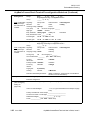
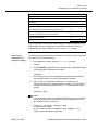
Quality Management System
The Quality Management System (QMS) for Lucent Technologies’ AnyMedia® Access Systems R&D
organizations has been registered to IS0 9001 under the Norwegian Scheme by Det Norske Veritas (DNV)
since June 1993. ISO 9001 is an international quality standard recognized by more than 90 countries
worldwide. It is a model for quality assurance in design, development, production, installation, and servicing.
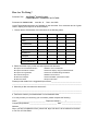
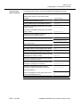
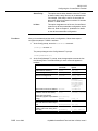
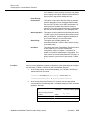
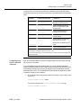
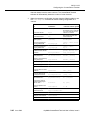
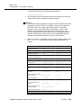
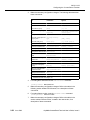
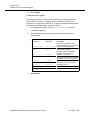
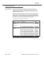
How Are We Doing?
Document Title:
Document No.:363-211-129
Issue No.: 5
Date: June 2002
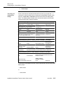
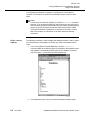
Lucent Technologies welcomes your feedback on this document. Your comments can be of great
value in helping us to improve our documentation.
0 &$>
Excellent
Good
Fair
Poor
Ease of Use
Clarity
Completeness
Accuracy
Organization
Appearance
Examples
Illustration
Overall Satisfaction
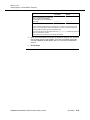
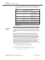
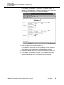
7 Please check the ways you feel we could improve this document:
7 Improve the overview/introduction
7 Improve the table of contents
7 Improve the organization
7 Include more figures
7 Add more examples
7 Add more detail
7 Make it more concise/brief
7 Add more step-by-step procedures/tutorials
7 Add more troubleshooting information
7 Make it less technical
7 Add more/better quick reference aids
7 Improve the index
Please provide details for the suggested improvement._________________________________
_____________________________________________________________________________
4 What did you like most about this document?
_____________________________________________________________________________
_____________________________________________________________________________
B Feel free to write any comments below or on an attached sheet.
If we may contact you concerning your comments, please complete the following:
Name: _______________________________ Telephone Number: (_____)_________________
Company/Organization: ______________________________ Date: _____________________
Address:_____________________________________________________________________
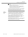
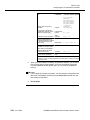
When you have completed this form, please fold, tape, and return it to the address on the back
or Fax it to: 973-581-6646.
--------------------------------------------------------------- Do Not Cut — Fold Here And Tape ------------------:'&'/)
:))/C
2@/!)#
:,)
:)#/)
!2
3
2!/&)@:'1 :)D&'?#):) :E
&'/)D!!")&/#"C/##)))
!
! 4 2
56
&'
(5 3
-7.%88
//
!9
#$%
(5 3*
+
$'#,-.$#$%
45467006078
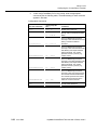
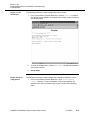
Table of
Contents
About This Document
1
2
3
4
Preinstallation Planning
About This Chapter
067
Configuration and Installation Process
064
Configuring the ConnectReach Terminal
About This Chapter
764
Preparing the ConnectReach Terminal for Initial
Configuration
76B
Using the Configuration Commands
7604
Reconfiguring the ConnectReach Terminal
76079
Installation
About This Chapter
464
What Are the Requirements?
461
Connector Pin Assignments
468
Interface Card Installation
460F
Mount the ConnectReach Terminal
467B
Connect Cables to the ConnectReach Terminal
464B
48-Line Master/Slave Configuration
46B5
Analog Voice Interface Considerations
461G
Alarm Relay
4614
ConnectReach Terminal Monitoring
About This Chapter
B64
Using the Statistics Command to Display System
Elements Status
B6B
Miscellaneous Monitoring Commands
B6B7
Issue 5
June 2002
:
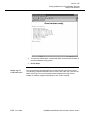
45467006078
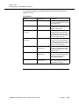
5
6
A
B
C
D
:
Configure/Monitor, and Upgrade Software for the
ConnectReach Terminal Using a Web Browser
About This Chapter
167
Preparing/Accessing the ConnectReach Terminal
164
Executing Commands from the Main Menu
165
Software Upgrade, Maintenance, and Trouble Clearing
About This Chapter
567
Maintenance Procedures
564
Trouble Clearing Procedures
560B
IP Network Addresses
About This Appendix
/60
IP Network Addresses Description
/67
Configuration Examples
About This Appendix
"60
Examples of the Different Methods of
Configuring the AnyMedia Access System
ConnectReach Terminal
"67
Custom Firewall Configurations
About This Appendix
60
Configuring IP Filter Groups
67
User Interface
June 2002
About This Appendix
#60
Business OfficeXchange Features
#67
Issue 5
45467006078
E
Configuring Enterprise NAT
About This Appendix
)60
, !60
%-
A60
Issue 5
June 2002
"
45467006078
"
June 2002
Issue 5
About This Document
0
Overview
Purpose
This document, AnyMedia® Access System, ConnectReach™ Terminal User’s
Guide, hereinafter referred to as the ConnectReach Terminal, provides the
following information:
• An overview of the system
• Specific information about the benefits, applications, features, and
operation of the product
• Configuration and engineering information for planning purposes
• Ordering information (for detailed ordering information, see the AnyMedia ®
Access System, Ordering Guide, code 363-211-125).
Intended audience
Customers who use this document include the following:
• Equipment engineers and outside plant engineers
• Transmission engineers
• Installation, operation, and maintenance personnel
• System administrators
• Technical support personnel
• Training personnel.
Issue
This is Issue 5 of the AnyMedia® Access System, ConnectReach™ Terminal
User’s Guide.
AnyMedia ConnectReach Terminal, User’s Guide, Issue 5
June 2002
xi
363-211-129
About This Document
Reason for reissue
The ConnectReach Terminal User’s Guide is being reissued to provide
information about the following new or changed features:
• Telnet port configuration commands (see Using a Telnet session to
reconfigure and monitor the ConnectReach Terminal on page 2-129).
• HTTP port configuration commands (see Using HTTP to manage the
ConnectReach Terminal on page 2-130).
• ARP protocol (see Using ARP on page 2-91) and statistics (see Displaying
Statistics for ARP on page 4-9).
• Port Address Translation (PAT) configuration (see Configuring NAT and PAT
on page 2-101) and statistics (see Displaying Statistics for NAT and PAT on
page 4-16).
• New Quickstart Configuration Example using NAT (see Quickstart
Configuration Example on page B-2). NAT examples (see NAT Examples
on page B-11).
• Enterprise NAT appendix added (see Appendix E, Configuring Enterprise
NAT).
• New Customized Configuration Example without firewall SOCKS (see
Customized Configuration Example on page B-5).
• Configure secondary IP address for the Ethernet Interface before enabling
Pass-Thru definition (see Pass-Thru on page 2-105 and Configuring the
Ethernet Interface on page 2-35).
• Channel Bank Configuration has on-hook-tx command (see Configuring the
Channel Bank Mode on page 2-37).
• Dialing Configuration has extension-prefix command (see Configuring
Dialing on page 2-68).
• SNMP Service commands has upsSnmp-enable command and additions to
Traps table (see Configuring the SNMP Service on page 2-84).
• Updated Frame Relay Interface Statistics (see Displaying Statistics for the
Frame Relay Interface on page 4-27).
• IP filtering changed to four filtergroups and sixteen filters (see Configuring
the Default Firewall on page 2-93 and Appendix C, Custom Firewall
Configurations).
• QOS has changed. For configuration, see Configuring QOS on page 2-111)
and for statistics see Displaying Statistics for QOS on page 4-8.
• UPS with special cables note (see Cables on page 3-8).
• Ethernet port transmission mode is half-duplex (see Connect the Ethernet
and T1 cables to the unit on page 3-42).
• New Line Statistics Events table (see Displaying Statistics and Setting/
Clearing Loopbacks on a T1 Interface on page 4-19).
• New SYSLOG command added (see “Configuring SYSLOG” on
page 2-115).
xii
June 2002
AnyMedia ConnectReach Terminal, Issue 5
363-211-129
About This Document
• New Lines Show-all response (see “Lines Show-all Response” on
page 2-64).
• New statistics commands: WAN FR Interface (show-frinterface) (see
“Displaying Statistics for the WAN Frame Relay Interface” on page 4-30),
Frame Relay PVCs (show-pvc) (see “Displaying Statistics for Frame Relay
PVCs” on page 4-33), and IP Protocols (show-ipsummary) (see “Displaying
Statics for IP Protocols” on page 4-35).
• New information for using the template archive (see “Using Template
Archive” on page 2-124).
• New information for using the service level agreement (SLA) (see “Using
the SLA commands” on page 2-31).
• SOCKS is no longer supported.
• IPX functionality is no longer supported.
Content
This issue of the ConnectReach Terminal contains the following:
• An overview of the ConnectReach Terminal
• A description of the system and its components
• Applications services and interfaces of the system
• Operations of the system
• Installation of the system
• Planning and engineering information for the system
• Ordering information for the system (for detailed ordering information, see
the AnyMedia® Access System, Ordering Guide, code 363-211-125)
• Table of contents, acronym list, glossary, and index for the document, which
help the reader find desired information quickly and easily
• A comment form so readers can give feedback to improve the next revision
of the document.
Document
organization
This guide describes how to configure, install, and manage the ConnectReach
Terminal. The information in this guide is organized as follows:
• About This Document
Defines the purpose of the document and the intended audience. Also
includes topics about the conventions used in the document, related
documentation, how to order documents, and how to comment on this
document.
AnyMedia ConnectReach Terminal User’s Guide, Issue 5
June 2002
xiii
363-211-129
About This Document
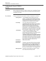
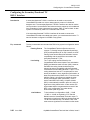
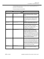
• Chapter 1, Preinstallation Planning
This chapter includes instructions for completing preconfiguration and
preinstallation worksheets that can be used to reduce the time it takes to
configure and install a ConnectReach Terminal.
• Chapter 2, Configuring the ConnectReach Terminal
This chapter contains procedures for configuring the ConnectReach Terminal
according to the settings selected on the preconfiguration worksheets.
These procedures assume that the ConnectReach Terminal is to be
configured at a staging area prior to installation at a customer site.
Procedures are also included for reconfiguring the ConnectReach Terminal
from a remote location after it has been installed.
• Chapter 3, Installation
This chapter provides the procedures for mounting and connecting cables
to the ConnectReach Terminal. The procedures for installing interface cards
into the ConnectReach Terminal and connecting two ConnectReach
systems together to obtain more than 24 voice channels are also included
in this chapter.
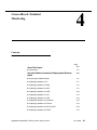
• Chapter 4, ConnectReach Terminal Monitoring
This chapter contains the procedures for accessing and displaying various
data that has been stored in or collected by the ConnectReach Terminal.
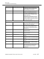
• Chapter 5, Configure/Monitor, and Upgrade Software for the ConnectReach
Terminal Using a Web Browser
This chapter contains the procedures for configuring, monitoring, and
performing software upgrades on the ConnectReach Terminal using a Web
browser. This chapter also includes the procedure for executing other
commands, rebooting the ConnectReach Terminal, and upgrading
ConnectReach Terminal.
• Chapter 6, Software Upgrade, Maintenance, and Trouble Clearing
This chapter contains the procedures for performing “as required”
maintenance and software upgrades on the ConnectReach Terminal. Also
included in this chapter is information to assist in the isolation of a trouble
condition using the indicators on the front of the ConnectReach Terminal
unit.
• Appendix A, IP Network Addresses
This appendix describes Internet protocol (IP) addressing including the five
classes of networks and the IP addresses that are valid for each one.
• Appendix B, Configuration Examples
This appendix contains examples of configuration sessions ranging from a
simple quickstart example to a more complex arrangement requiring many
parameter settings.
• Appendix C, Custom Firewall Configurations
This appendix contains procedures for configuring IP filter groups.
• Appendix D, User Interface
This appendix includes the procedures for using the Business
OfficeXchange (BOX) features.
xiv
June 2002
AnyMedia ConnectReach Terminal, Issue 5
363-211-129
About This Document
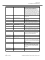
• Appendix E, Configuring Enterprise NAT
This appendix describes the configuration of and applications for Enterprise
Network Address Translation (Enterprise NAT).
• Glossary
Defines acronyms and terms that may be unfamiliar to the user.
• Index
Lists in alphabetical order the specific subject information in the document.
AnyMedia ConnectReach Terminal User’s Guide, Issue 5
June 2002
xv
363-211-129
About This Document
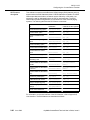
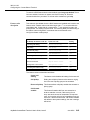
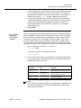
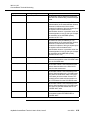
Conventions Used in This Document
%$>
Terms used
courier
2
% @33>
(config)>
courier bold
2% >
(config)> password
courier italic $$
2% >
(config:Password)> user name
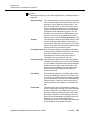
The following are terms used in this document that may have a different meaning
than the general or common use of the term.
• In the AnyMedia Access System, the term access means that the system
provides the primary service interface for the customer to enter the network.
Acronyms and
abbreviations
In the first chapter, acronyms are spelled out in lower case letters the first time
they are used. Acronyms are also expanded if the section topic is specifically
about the acronym.
Initial caps are used only when the acronym represents a system (e.g., the
Mechanized Loop Testing [MLT] system) or when used in a heading. If the
acronym is a trademark, it will not be spelled out.
Trademarks
The trademarks used in this document are identified for the first time on the
trademark page. Trademarks of Lucent Technologies and other companies are in
italics, and the trademarks modify a noun (e.g., the system name contains a
registered trademark, AnyMedia Access System). A trademark is not treated as
an acronym (it is not spelled out or expanded).
Lucent Technologies trademarks
0
Lucent Technologies trademarks are identified with the registered mark ( ® ) or
trademark ( ™ ) symbol the first time the trademarks are used in the text.
Trademarks of other companies
0
The trademarks of other companies are identified for the first time on the
trademark page. Trademark references from there on are in italics.
xvi
June 2002
AnyMedia ConnectReach Terminal, Issue 5
363-211-129
About This Document
Related Documentation
Document list,
packaging, and
formats
he following documentation is available for the AnyMedia Access System:
Available on the Web
0
• AnyMedia Access System Documents
— 363-211-125, AnyMedia® Access System, Ordering Guide
http://www.lucent8.com/library/AnyMediaOrderingGuide.pdf
Available on CD-ROM
0
363-211-103, AnyMedia® Access System, Documentation, which is a
CD-ROM that contains the following documents in various formats:
• AnyMedia Access System Documents
— 363-211-101, AnyMedia® Access System, Applications, Planning, and
Ordering Guide (APOG) (in PDF format)
— 363-211-125, AnyMedia® Access System, Ordering Guide (also has a
link to the website:
http://www.lucent8.com/library/AnyMediaOrderingGuide.pdf)
— 363-211-106, AnyMedia® Access System, Feature Supplement—MDS2
Shelf Configurations (in PDF format)
— 363-211-127, AnyMedia® Access System, Feature Supplement—
Integrated Access Terminal (in PDF format)
— 363-211-128, AnyMedia® Access System, Feature Supplement—
Central Office Terminal (in PDF format)
— 363-211-102, AnyMedia® Access System, Installation Manual (in PDF
format)
— AnyMedia® Access System, Commands and Procedures (363-211-100,
in HTML format, also includes PDFs of selected procedures)
— 363-211-129, AnyMedia® Access System, ConnectReach™ Terminal
User’s Guide (in PDF format)
— 363-211-130, AnyMedia® Access System, ConnectReach Plus™
Terminal User’s Guide (in PDF format)
— 363-211-520, AnyMedia® Access System (24 Channel) Optical Network
Unit Installation Manual for Outdoor Applications (in PDF format)
— 363-211-521, AnyMedia® Access System (24 Channel) Optical Network
Unit Installation Manual for Indoor Applications (in PDF format)
• Cabinet Documents
— 631-600-290,AnyMedia® Access System, 82-Type Outdoor Electronics
Cabinets (in PDF format)
— 631-600-293 AnyMedia® Access System, 52B and 52E Outdoor
Electronics Cabinets (in PDF format)
AnyMedia ConnectReach Terminal User’s Guide, Issue 5
June 2002
xvii
363-211-129
About This Document
— 640-250-307, AnyMedia® Access System, 92-Type Indoor Electronics
Cabinets Description, Installation, and Operations (to be supplied at a
later date in PDF format)
• SLC Documents
— SLC Series 5 Carrier System J1C182BC-1 Remote Terminal Ring Shelf,
User Manual (in PDF format)
An Adobe Acrobat Reader is provided to view all PDF files.
For documents in HTML format, users need and must supply their own Web
browser to view them. The documentation has been verified using the
following Web browsers: Netscape Navigator 4.0 and Internet Explorer 5.0
or later.
The AnyMedia Access System Management Interface, which includes the
graphical system interface (GSI) and the Network Maintenance Manager, is
available on CD-ROM.
xviii
June 2002
AnyMedia ConnectReach Terminal, Issue 5
363-211-129
About This Document
How to Order This Document
Ordering number
The ordering number for the AnyMedia® Access System, ConnectReach Terminal
is 363-211-129.
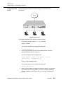
Order procedure
To order additional hard copies of this document and/or to request placement on
the standing order list, send or call in an order as follows:
!
. (
(
∗
!
/>')
7911:23
&'"%088G0
:B5708
6D/>-.,,,.2,
()*+,-,.)*+!,-,
62/A/>
-.,$$.;&&.#;&,
62/AD>
-.%-'.%88.&&##
!
%
&#
∗2 3 .@33!!
2:#069G9G2/ $
One-time orders
One-time orders include the contents for the current document issue in effect at
the time of order.
Standing orders
You may request placement on the standing order list for all later reissues of any
document. The standing order list for each document provides automatic
distribution for all reissues of the document.
Local exchange
carrier orders
Local exchange carrier customers should process documentation orders or
standing order requests through their Company Documentation Coordinator.
AnyMedia ConnectReach Terminal User’s Guide, Issue 5
June 2002
xix
363-211-129
About This Document
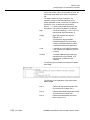
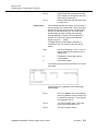
How to Comment on This Document
Document comment
procedure
Please send or fax your comments and suggestions concerning the User’s Guide,
363-211-129 to:
Attention: Lucent Technologies
Attn: Customer Documentation Coordinator
Room 15D-322
PO Box 903
67 Whippany Road
Whippany, NJ 07981-0903
Fax: 973-386-2388
xx
June 2002
AnyMedia ConnectReach Terminal, Issue 5
Preinstallation Planning
1
Contents
page
About This Chapter
3
Introduction
Configuration and Installation Process
1-2
1-2
1-3
3
Summary
1-3
3
Quickstart Configuration
1-5
3
Customized Configuration
1-7
AnyMedia ConnectReach Terminal User’s Guide, Issue 5
E7GG7
1-1
45467006078
&&
About This Chapter
Introduction
Contents
1-2 E7GG7
This chapter provides information about the following topics as they relate to the
ConnectReach Terminal:
3
Summary of the configuration and installation process
3
Discussion on the private and public switched networks
3
Quickstart and customized configurations
3
Preinstallation and preconfiguration worksheets.
AnyMedia ConnectReach Terminal User’s Guide, Issue 5
45467006078
&&
Configuration and Installation Process
Summary
Introduction
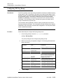
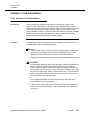
This section presents the steps required to configure and install the
ConnectReach Terminal. The more information you can gather about the
customer site before beginning to configure and install the ConnectReach
Terminal, the easier the process will be.
Customer site data
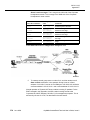
The complexity of a given ConnectReach Terminal installation depends mainly on
one factor; namely, whether or not the site is considered a “private” data network.
In a private data network, addresses are obtained from a common pool of
addresses and are not guaranteed to be unique on the Internet. Therefore, to
prevent confusion over packet destinations, the addresses cannot be visible to the
Internet. Instead, an address translating scheme, such as combined Network
Address Translation (NAT) and Port Address Translation (PAT), can be used to
manage the mapping of packets to the appropriate destination on the private
network.
Appendix A, IP Network Addresses describes private network addresses in more
detail.
Configuration and
installation process
summary
The following steps provide a summary of the action required to configure and
install the ConnectReach Terminal:
1.
Verify that the site meets the installation and site requirements (listed in
Chapter 3, Installation).
2.
Use the Preinstallation Worksheet to record the site’s installation
requirements.
3.
Using the Preconfiguration Worksheet, record the site’s configuration
requirements.
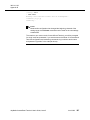
NOTE:
The procedures in this manual are written with the assumption that the
ConnectReach Terminal will be configured in a staging area before it is
installed at the customer site. If the ConnectReach Terminal is to be
configured after installation, then the ConnectReach Terminal should be
installed next using the procedures in Chapter 3, Installation, and then
configured using the procedures in Chapter 2, Configuring the
ConnectReach Terminal.
AnyMedia ConnectReach Terminal User’s Guide, Issue 5
E7GG7
1-3
45467006078
&&
4.
Apply power to the ConnectReach Terminal and observe the self-test lightemitting diodes (LEDs) to verify that the unit is starting up successfully. For
the self-test status information, refer to Chapter 6, Software Upgrade,
Maintenance, and Trouble Clearing.
5.
In a staging area, configure the ConnectReach Terminal according to the
Preconfiguration Worksheet. (Chapter 2, Configuring the ConnectReach
Terminal, describes the utility program used to configure the
ConnectReach Terminal.)
6.
Save the new configuration in the ConnectReach Terminal’s nonvolatile
random access memory (NVRAM). (Refer to Chapter 2, Configuring the
ConnectReach Terminal.)
7.
At the customer site, install the ConnectReach Terminal and connect all the
required cables according to the Preinstallation Worksheet. (Chapter 3,
Installation, describes the ConnectReach Terminal installation procedure.)
8.
Apply power to the ConnectReach Terminal and observe the self-test light
emitting diodes (LEDs) to verify that the unit is starting up successfully. For
the self-test status information, refer to Chapter 6, Software Upgrade,
Maintenance, and Trouble Clearing.
9.
If necessary, make any final configuration changes after physical
installation is complete (refer to Chapter 2, Configuring the ConnectReach
Terminal). Remember to save the revised configuration and reboot the
ConnectReach Terminal using the procedure in Chapter 6, Software
Upgrade, Maintenance, and Trouble Clearing, so that the changes take
effect.
10.
Changing the
configuration
settings
Perform channel unit provisioning and DS0 cross-connection procedures
from the AnyMedia Access System.
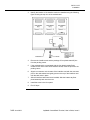
After the ConnectReach Terminal is configured and installed at the site, you can
change its configuration by means of the graphical system interface (GSI) at the
ConnectReach Terminal or a Telnet session or hypertext transfer protocol (HTTP)
connection either from the local Ethernet or over the T1 link from the carrier
central office (CO). If a modem is permanently connected to the RS-232 port, you
can also change the configuration by means of a dial-up connection. If the T1
connection to the ConnectReach Terminal is down, you can use the Ethernet
connection or the dial-up connection.
For more information about using a Telnet session, refer to Chapter 2, Configuring
the ConnectReach Terminal. For more information about HTTP connections, refer
to Chapter 5, Configure/Monitor, and Upgrade Software for the ConnectReach
Terminal Using a Web Browser.
1-4 E7GG7
AnyMedia ConnectReach Terminal User’s Guide, Issue 5
45467006078
&&
Quickstart Configuration
Description
The quickstart configuration is for channel bank configurations only where default
settings are used for all or most of the configuration parameters. Refer to
Appendix B, Configuration Examples, for a quickstart example of the local call
routing*/direct inward dialing (LCR/DID) configuration.
Quickstart
configuration
planning process
Unless stated otherwise, the numbered steps below are in the same order as the
numbered areas on the Preconfiguration Worksheet presented later in this
chapter. Default values, where applicable, are shown in parentheses below and in
bold on the worksheet. For detailed information about parameters and the
possible values, refer to Configuring the ConnectReach Terminal on page 2-1.
1.
Determine whether the Network T1/DSX-1 default values match the carrier
configuration of the T1 line. Since the ConnectReach Terminal will always
connect to an AnyMedia Access System, the Network T1/DSX-1 framing
format and line coding will be extended superframe (ESF) and bipolar 8
zero substitution (B8ZS), respectively.
2.
If the ConnectReach Terminal will have a T1 connection to the site phone
system, determine whether the Secondary T1/DSX-1 default values match
the configuration of the T1 connection to the phone system.
3.
DS0 provisioning (voice and data channel assignments). The default
channel assignments correspond to the actual hardware configuration. If
these are appropriate, you do not need to set or change the channel
assignments.
— Number of analog voice channels (channels set according to actual
hardware)
— Number of secondary T1/DSX-1 voice channels (none)
— Number of data channels (none). Must be set.
4.
Synchronous interface information:
— Encapsulation scheme used on the link to the CO (frame relay)
— ConnectReach Terminal IP address on the link to the data network
— Netmask (if any) for that address
— If frame relay, the data link connection identifier (DLCI) assigned to
the ConnectReach Terminal
— If frame relay, the local management interface (LMI) type used in
signaling.
5.
To configure the channel bank, you will need to know the CO digital trunk
configuration and the configuration of the equipment [analog phones,
private branch exchange (PBX), or key system] at the site [number 6
(Channel bank) on the worksheet]. The following is a list of data:
AnyMedia ConnectReach Terminal User’s Guide, Issue 5
E7GG7
1-5
45467006078
&&
— Trunk type [loop-ground-foreign exchange office/direct inward
dialing (FXO/DID)]
— Loop reversal from CO (enabled)
— Transmit gain (–3 db)
— Receive gain (–3 db)
— On-hook threshold (300 milliseconds)
— Alarm state (busy)
— State of unconfigured channels (idle).
6.
1-6 E7GG7
Obtain the local site’s domain name [number 14 (DHCP) on the
worksheet].
AnyMedia ConnectReach Terminal User’s Guide, Issue 5
45467006078
&&
Customized Configuration
Description
This customized configuration procedure applies if the site is not a private
network, or if other default parameter values are not appropriate.
Customized
configuration
planning process
The data that should be available before beginning the configuration procedure is
listed below. The numbered steps correspond to numbered areas on the
Preconfiguration Worksheet (presented later in this chapter).
Because the ConnectReach Terminal supports many interfaces and protocols, the
ConnectReach Terminal configuration utility offers a large number of configuration
parameters. However, almost all parameters have default values; if a parameter’s
default is appropriate for the customer site, you do not need to set the parameter.
Default values, where applicable, are shown in parentheses below and in bold in
the worksheet. All parameters listed below are described in more detail in
Chapter 2, Configuring the ConnectReach Terminal.
1.
Network T1/DSX-1 interface configuration. You need the following
information:
— Framing format (ESF)
— Line coding format [bipolar 8 zero substitution (B8ZS)]
— Build-out (0 dB)
— Clock source (network)
— Pulse density enforcement (off)
— Alarm (on) delay (15 seconds)
— ConnectReach Terminal is a slave (off)
— IP over FDL: IP address and netmask.
2.
Secondary/Fractional T1 DSX1 configuration. For this interface to the
phone system, You need the following information:
— Framing format (ESF)
— Line coding format (B8ZS)
— Build-out (0 dB)
— Pulse density (off)
— Alarm (off) delay (15 seconds)
— ConnectReach Terminal has a slave (off).
3.
DS0 provisioning. Voice and data channel assignments require the
following data:
— Number of analog voice channels (channels set according to actual
hardware), need begin and end range.
AnyMedia ConnectReach Terminal User’s Guide, Issue 5
E7GG7
1-7
45467006078
&&
— Number of secondary/fractional T1/DSX-1 voice channels (none)
— Number of data channels, need begin and end range.
— Number of secondary/fractional T1/DSX-1 data channels (none)
— Alignment secondary fractional T1/DSX1 (low)
— ConnectReach provisioning, need range for each CU.
— ClearReach feature (off)
4.
Synchronous interface configuration.
HDLC inversion. Determine whether the synchronous interface should
use HDLC inversion for pulse density enforcement (off). Pulse density
enforcement applies only when the network T1/DSX-1 interface line coding
format is set to alternate mark inversion (AMI), regardless of the
encapsulation scheme selected.
Determine whether the synchronous interface (the Network T1/DSX-1
interface) uses the following:
— Frame relay and how many PVCs (1 to 30) to be defined
— SLA
— Point-to-point protocol (PPP)
— HDLC.
Determine the following address information for each synchronous
interface (disabled): ConnectReach Terminal IP address on the link to the
carrier CO, or Enet (IP unnumbered), or Netmask (if any).
Frame relay. If the interface uses frame relay encapsulation, yYou need
the following information:
— Local management interface (LMI) type (T1.617 Annex D/ANSI))
— N391* polling cycles for permanent virtual circuits (PVCs) (6)
— N392* threshold (3)
— N393* monitored event counter (3)
— T391* link integrity polling timer (6).
PVC 1-30. Each PVC submenu allows the user to configure DLCI and IP
commands.
— DLCI number assigned to the ConnectReach Terminal
— RIP (diable)
— RIP version (1)
*
It is recommended that the default values be used for these parameters.
1-8 E7GG7
AnyMedia ConnectReach Terminal User’s Guide, Issue 5
45467006078
&&
— NAT (out)
— SLA (disable). A Service Level Agreement (SLA) is a contract
between a carrier and a customer that specifies a measurable level
of service the carrier will provide.
— SLA Thresholds. Choose SLA thresholds: latency, above CIR,
below CIR, PVC down.
PPP. If the interface uses PPP, You need the following information:
— IP address of the remote peer PPP device (disable)
— Netmask (if any) for that address.
— RIP (disable)
— RIP version (1).
HLDC. If the interface uses HDLC, You need the following information:
— IP address (disable)
— Netmask (if any) for that address
— RIP (disable)
— RIP version (1).
5.
Ethernet interface configuration. You need the following information:
— ConnectReach Terminal IP address on the network on which it will
be installed (192.168.0.1)
— Netmask (if any) for the network on which the ConnectReach
Terminal will be installed (255.255.255.0)
— Secondardy IP Address (0.0.0.0)
— Secondary netmask (255.255.255.0)
— RIP (disable)
— RIP version (1)
— 10Base-T link integrity testing (on).
If you are using a secondary Ethernet interface, you will need to specify the
IP address and netmask for this interface.
Appendix A, IP Network Addresses, describes the IP address scheme and
subnets. If the site already has an IP network that uses subnets, you
should obtain the netmask information from the network administrator.
6.
Channel bank configuration. For an analog interface to the phone
system, You need the following information:
— Channel Range for begin and end
— Signaling (Loop-ground)
— Analog interface (FXS loop start)
AnyMedia ConnectReach Terminal User’s Guide, Issue 5
E7GG7
1-9
45467006078
&&
— Loop reversal from CO (disabled)
— Transmit gain (–3 dB)
— Receive gain (–3 dB)
— On-hook threshold (1250 milliseconds)
— Alarm state (busy)
— State of unconfigured channels (idle)
— Loop ground disconnect delay (600 msec)
— Cross connect. Each DS0 to a line.
E&M signaling requires the additional following data:
— Type of incoming (wink-start)
— Type of outgoing (wink-start)
— Analog interface (current feed loop start)
— Far end disconnect (enabled).
NOTE:
In the ConnectReach Terminal, references to E&M signaling refer to a
signaling type supported on DID trunks. It does not refer to the E&M
signaling used over metallic leads with older transmission equipment.
7.
Digital trunk configuration. The Digital trunk menu is part of the LCR/DID
optional feature. The DID and trunk signaling parameters for each digital
trunk (DS0) are set here. You need the following information:
— Range for begin and end
— Trunk group (1)
— Trunk signaling (unconfigured)
— Direction (two-way)
— Incoming routing (DID-DNIS)
— Line group (1)
— Digit type [dial tone multifrequency (DTMF)]
— Busy treatment (busy signal)
— Busy line forward (24)
— Transmit gain (–3 dB)
— Receive gain (–3 dB).
E&M signaling requires the additional following data:
— Type of incoming (wink-start)
— Type of outgoing (wink-start).
1-10 E7GG7
AnyMedia ConnectReach Terminal User’s Guide, Issue 5
45467006078
&&
NOTE:
In the ConnectReach Terminal, references to E&M signaling refer to a
signaling type supported on DID trunks. It does not refer to the E&M
signaling used over metallic leads with older transmission equipment.
8.
Analog trunk configuration.The Analog trunk menu is part of the LCR/
DID optional feature. The DID and trunk signaling parameters for each
analog trunk (FXO) are set here. You need the following information:
— Range for begin and end
— Trunk group (2)
— Trunk signaling (unconfigured)
— Direction (two-way)
— Incoming routing (group)
— Line group (1)
— Digits type (DTMF)
— Busy treatment (busy signal)
— Busy line forward (24)
— Transmit gain (–3 dB)
— Receive gain (–3 dB).
9.
Line configuration. The Line menu is part of the LCR/DID optional
feature.The line signaling parameters for the LCR/DID lines are set here.
You need the following information:
— Range for begin and end
— Line group (1)
— Line signaling (unconfigured)
— Direction (two-way)
— Outgoing routing (LCR)
— Trunk group (1)
— On-hook threshold (1250 milliseconds)
— Far end disconnect (enable)
— Polarity reversal (enable)
— Trunk ring default (double)
— Paging line (0)
— Hunting (most idle)
— Business OfficeXchange (BOX) features (refer to Chapter 2,
Configuring the ConnectReach Terminal, for more information).
AnyMedia ConnectReach Terminal User’s Guide, Issue 5
E7GG7
1-11
45467006078
&&
10.
Map extension configuration. The Map Extension menu is part of the
LCR/DID optional feature. The extension table associates phone
extensions with analog lines.
— Extension digits (2).
— Assign extension numbers to line numbers with the option of an
alternate extension. All extension numbers must be unique.
11.
Dialing configuration. The Dialing menu is part of the LCR/DID optional
feature. The dialing table routes calls to digital or analog trunks and
translates special numbers such as 411, 611, and 911 to seven- or ten-digit
numbers. Refer to Chapter 2, Configuring the ConnectReach Terminal, for
more information. You need the following information:
— Pattern of detected digits
— Action on detected digits
— Primary and alternate trunk groups
— Trunk access code or local digits
— DID received digits (2)
— Pause (2000).
12.
Voice mail configuration. A group of lines may be configured to interface
with a voice mail system. The voice mail configuration allows for custom
configuration as well as five preset voice mail profiles. Refer to Chapter 2,
Configuring the ConnectReach Terminal, for more information. You need
the following information:
— Enable (off)
— Line group (5)
— Integration delay (500 ms)
— Stutter tone (off)
— Periodic ring (off)
— DTMF settings for direct prefix, ring no answer, busy no answer,
forward all, unforward, and message waiting indicators.
— Preset profile for generic or listed companies.
13.
Login name and password configuration. For security, it is
recommended that you configure login names and passwords to be used
by individuals who require access to the ConnectReach Terminal for
configuration and management. Two privilege levels are available and you
may set up one login name and password for each privilege level.
NOTE:
If you are upgrading to version 5.x.x of the ConnectReach Terminal
software from version 3.6.x, IPX functionality will no longer be supported.
1-12 E7GG7
AnyMedia ConnectReach Terminal User’s Guide, Issue 5
45467006078
&&
14.
DHCP service. If the site uses the Dynamic Host Configuration Protocol
(DHCP) on the ConnectReach Terminal to allocate IP addresses
dynamically to devices on the network, you need the following information:
— Enable (off)
— First and last of the IP address pool to be used at the site
— Whether or not the site is considered a private network. Appendix A,
IP Network Addresses describes the use of private IP network
addresses (on)
— Lease time of DHCP-allocated addresses (600)
— IP address of domain name service (DNS) server (192.168.0.1)
— Local site’s domain name.
If the site already has a DHCP server, or if each network device will be
permanently assigned a unique IP address, you do not need to enable and
configure DHCP on the ConnectReach Terminal.
15.
Simple network management protocol (SNMP) service. If SNMP traps
are sent automatically to a remote host, you must specify the IP address of
the host that will receive the SNMP traps. This is usually an SNMP host on
the carrier’s management network, so maintenance staff is aware of
changes in equipment status before getting calls from the customer site.
If you enable SNMP, you should also enable some or all of the possible
SNMP trap types (see the Preconfiguration Worksheet for the list).
— Enable (off)
— SNMP host IP address
— Enable messages
— Cold start (off)
— Warm start (off)
— Link down (off)
— Link up (off)
— Login failures (off)
— T1 traps: select ESs, SESs, SEFs, UASs, CSSs, PCVs,
LESs, BESs, DMs, LCVs.
16.
HTTP (Web browser) port. Configure the ConnectReach Terminal
remotely using a Web browser through an Ethernet or Internet/T1
connection (an IP connection over T1 using Frame Relay, PPP, or HDLC).
The Web browser feature is enabled by default (on).
17.
Telnet Port configuration. Before you can use a Telnet session to make
configuration changes on the ConnectReach Terminal, the unit must be
connected to the provided AC transformer, or 24 VDC power, initially
AnyMedia ConnectReach Terminal User’s Guide, Issue 5
E7GG7
1-13
45467006078
&&
configured for an Ethernet or Internet/T1 connection, including an IP
address, netmask, and broadcast address or connected to the network
through an Ethernet or T1 connection.
You must also have a computer that is connected to the same network as
the ConnectReach Terminal, or to a network from which access to the
ConnectReach Terminal is permitted. Once you are connected and have
access, you can configure the Telnet parameters. Telnet is enabled by
default (on).
18.
Route configuration. The ConnectReach Terminal allows the user to set a
default route and up to ten static routes. For ease of configuration, the user
may specify wide area network (WAN) or PVCn instead of an IP gateway
address. For each default or static route you must specify:
— Network IP address
— Netmask
— WAN, PVCn or gateway IP address.
19.
Network address translation (NAT) and port address translation (PAT)
configuration. NAT allows internal IP addressed workstations access to
the Internet through the use of an external IP address pool. NAT allows the
mapping of a range of LAN IP addresses to a range of WAN IP addresses.
The relation of the mapping may be one-to-one, many-to-one, or many-tomany. The three definitions are static allocations, dynamic allocation, and
pass-through. NAT is disabled by default (off).
PAT allows users on the public (WAN) side of a network to access specific
applications, or specific services, such as those provided by a Web server,
an email server (pop3), or an FTP server on the private (LAN) side of the
network.
To configure NAT in the dynamic definition, you need the following
information:
— Definition of traffic between LAN and WAN: dynamic allocation,
static allocation, or pass-thru.
— Source and end of LAN IP address
— Source and end of WAN IP address.
— Whether or not to allow Inbound connection. (In a one-to-one
relation, only Outbound connection is allowed, from LAN to WAN).
To configure PAT in the definition, you need the following information for
each NAT group you defined:
— Protocol
— Port number
— Keyword
— Inband IP.
1-14 E7GG7
AnyMedia ConnectReach Terminal User’s Guide, Issue 5
45467006078
&&
20.
ARP configuration. Address resolution protocol (ARP), is a TCP/IP
protocol used to convert IP addresses to physical addresses, such as
Ethernet (MAC) addresses. To configure ARP you need the following
information:
— IP address
— Ethernet address.
21.
Firewall configuration. The ConnectReach Terminal incorporates the IP
filtering firewall technology. For most installations, configuring the firewall is
extremely simple. The ConnectReach Terminal allows the following two
standard firewall configurations:
— IP filter
— IP filter plus server.
22.
Network time protocol (NTP) configuration. NTP is used to obtain the
time of day for time-stamping the event log messages. NTP is enabled by
default (on). You must specify the following for NTP:
— IP address or host name of the server
— The difference in minutes between local time and Greenwich Mean
Time (GMT).
23.
DNS Proxy Service. The ConnectReachTerminal uses DNS servers to
resolve host names for internal commands such as ping and network
upgrade. The DNS is enabled by default (on). To use this service, you will
need the following information:
— IP address of primary DNS server
— IP address of secondary DNS server.
24.
IP Quality of service (QoS) configuration. IP QoS allows prioritizing the
IP packets going out the WAN link. The priority routes are defined by the
source IP address, destination IP address, or source and destination IP
addresses. The IP address may either be a host or a subnet. QoS is
disabled by default (off). For QoS configuration you need the following
information:
— Source and/or end of the IP address to be used at the site
— Source and destination Netmask.
25.
RS-232 port baud rate. If the ConnectReach Terminal will have a modem
permanently attached to the RS-232 port to allow remote configuration and
management, and if the modem is capable of operating at speeds higher
than 9600 baud, you should set the RS-232 port baud rate to match the
modem’s data terminal equipment (DTE) speed. Available baud rates are
(9600 default), 19200, and 38400.
26.
SYSLOG utility. The SYSLOG utility creates a log of messages reporting
significant events occurring on an IAD, and makes this log available to a
remote computer. SYSLOG is enabled by default (on). You need the
following information to use this function:
AnyMedia ConnectReach Terminal User’s Guide, Issue 5
E7GG7
1-15
45467006078
&&
— IP address of host
— IP add/name of source
— sysconf facility or access facility.
1-16 E7GG7
AnyMedia ConnectReach Terminal User’s Guide, Issue 5
45467006078
&&
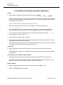
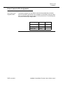
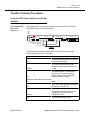
ConnectReach Terminal Preinstallation Worksheet
General
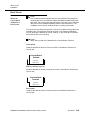
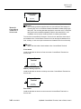
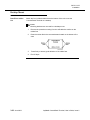
1. Where will the ConnectReach Terminal be placed? (circle one) RACK
(19” 23”)
WALL
DESKTOP
(A rack mount kit for ANSI*-type frames and a wall mount kit is included with all units, rubber feet are
included for desktop placement.) If rack mounted, allow 1.75" above unit for cooling. Wood screws for
wall mounting are not included.
*ANSI is a registered trademark of American National Standards Institute, Inc.
2. What is the distance from the Network T1/DSX-1 Demarc? (Connector type RJ48C)
____________________
(A 10 foot cable is included with each ConnectReach Terminal, a custom cable is required if the
distance is greater than 10 feet. See 363-211-125, AnyMedia Access System, Ordering Guide)
3. If AC powered, is the power receptacle within six feet of where the unit will be located?
Y
N
Power requirement: 120 V AC at 1 Amp
4. If DC powered, a DC power cable is included.
5. If battery backup is desired, refer to 363-208-000, AnyMedia Access System, Applications, Planning,
and Ordering Guide for ordering information.
Coordinate with the PBX vendor to be on-site for the installation of the ConnectReach Terminal in case
any changes need to be made to the routing parameters, etc.
Analog Voice
6. What is the distance between the ConnectReach Terminal and the PBX/KTS or patch panel?
__________
Analog channels are available on a standard female RJ21X 25 pair connector (order the appropriate
cable length).
Secondary/Fractional T1/DSX-1 RJ48C (Optional)
7. What is the distance between the ConnectReach Terminal and the PBX/KTS or patch panel?
__________
Pinouts are the same as the Network T1/DSX-1, a rollover/crossover cable is required to connect to
the PBX or KTS. The cable pin outs are shown in Chapter 3, Installation.
Ethernet 10BaseT
8. What is the distance between the ConnectReach Terminal and the 10BaseT hub?
___________________
(Order or make appropriate cable length)
AnyMedia ConnectReach Terminal User’s Guide, Issue 5
E7GG7
1-17
45467006078
&&
ConnectReach Terminal Preinstallation Worksheet (Continued)
RS232 Craft Port
9. Uses standard 9 pin female/female null modem cable to connect to PC (not included)
Remote Configuration or Diagnostics
10. Will a modem be used for remote configuration or diagnostics?Y
N
If yes was circled, order a 1 MB (Measured Business) line
Is a modem cable required? (Connector on the ConnectReach Terminal requires a standard 9 pin
female PC modem cable) Y
N
1-18 E7GG7
AnyMedia ConnectReach Terminal User’s Guide, Issue 5
45467006078
&&
NOTE:
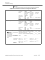
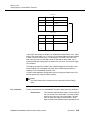
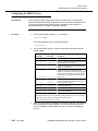
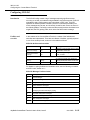
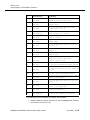
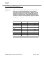
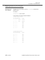
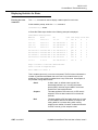
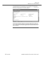
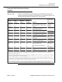
In the following worksheet, the default values (if any) appear in bold type.
AnyMedia ConnectReach Terminal Preconfiguration Worksheet
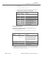
1.
2.
3.
Network
T1/DSX-1
Secondary/Fractional T1 DSX1
DS0 Provisioning
Framing Format:
4ESF
4D4/SF
Line Coding:
4B8ZS
4AMI
Buildout:
40-133 ft / 0 dB 4133-266 ft
4266-399 ft
4 399-533 ft
4 533-655 ft
4–7.5 dB
4 –15 dB
4 –22.5 dB
Clock Source:
4Network
4Internal
Pulse Density:
4Off
4On
Alarm:
4Off
4On
Is-slave:
4Off
4On
Delay: ______
(0...15...3600 sec.)
IP over FDL
IP address___________
4Off
4On
netmask_______________
Framing Format:
4ESF
4D4/SF
Line Coding:
4B8ZS
4AMI
Buildout:
40-133 ft / 0 dB 4133-266 ft
4266-399 ft
4 399-533 ft
4 533-655 ft
4–7.5 dB
4 –15 dB
4 –22.5 dB
Pulse Density:
4Off
4On
Alarm:
4Off
4On
Has-slave:
4Off
4On
Delay: ______ (0...15...3600 sec.)
Voice Channels: 4Analog channel range: Begin ____ End ____
Note: A total of 24
Data Channels:
channels are
available. Ranges
must not overlap.
Channels assigned Alignment Sec/
Frac. T1/DSX1:
in blocks of four
DS0s.
ConnectReach
Provisioning
ClearReach
Feature
4Sec./Frac. T1/DSX-1 voice channel range: Begin ____ End ___ (none)
4Data channel range: Begin ____ End ____
4Sec./Frac. T1/DSX-1 data channel range: Begin ____ End ____ (none)
4 Low
4 Same
Range: 1—4
CU: _____
Range: 5—8
CU: _____
Range: 9—12
CU: _____
Range: 13—16
CU: _____
Range: 17—20
CU: _____
Range: 21—24
CU: _____
4Off
4On
AnyMedia ConnectReach Terminal User’s Guide, Issue 5
E7GG7
1-19
45467006078
&&
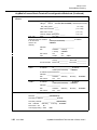
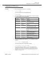
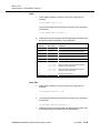
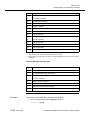
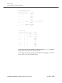
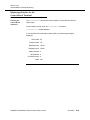
AnyMedia ConnectReach Terminal Preconfiguration Worksheet (Continued)
4.
Synchronous
Interface
HDLC Inversion: 4Off
4Frame Relay
4On
DLCI: ________ (16…991)
4None
LMI type:
PVC 1-30
N391 polling cycles: ______
(1...6...255)
N392 event threshold: ______
(1...3...255)
N393 event counter: ______
(1...3...10)
T391 link integrity polling timer: ______
(1...6...10)
DLCI:
(16...991)
(Duplicate and fill IP Address:
in for each PVC
that is to be
defined.)
4SLA
4______________________________&
4)*&+
4Disable
Netmask:
___________________________
RIP
4)
%'
%'
<
RIP version
41
42
NAT:
4&
4
4Enable
4
4Disable
Latency _____________ Above CIR ____________
Below CIR ___________ PVC Down ____________
SLA Thresholds:
4PPP
4T1.617 (Annex D/ANSI) 4Q.933 (Annex A/ITU)
4_______________________IP address
4Enet (IP unnumbered)
4Disable
IP address:
IP address of peer PPP device: _________________
Netmask: _________________
4HDLC
RIP:
4Enable
4RxOnly
4TxOnly
4Disable
RIP version:
41
IP address:
4_______________________IP address
4Enet (IP unnumbered)
4Disable
42
Netmask: _________________
5.
RIP:
4Enable
RIP version:
41
4RxOnly
4TxOnly
4Disable
42
Ethernet Interface IP address: _________________ (192.168.0.1)
Netmask: _________________ (255.255.255.0)
Secondary IP address: _________________(0.0.0.0)
Secondary netmask: _________________ (255.255.255.0)
RIP:
4Enable
RIP version: 41
4Rx Only
Link integrity testing: 4Off
1-20 E7GG7
4Tx Only
4Disable
42
4On
AnyMedia ConnectReach Terminal User’s Guide, Issue 5
45467006078
&&
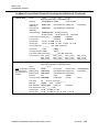
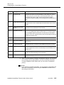
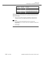
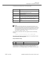
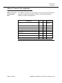
AnyMedia ConnectReach Terminal Preconfiguration Worksheet (Continued)
6.
Channel Bank
Range:
Begin _____ (1...24)
End _____ (1...24)
Beginning and ending of configuration blocks.*
Signaling:
4Loop-ground 4E&M
4Unconfigured
Incoming type:
(E&M only)
4Wink start
4Immediate start 4Delay dial
Outgoing type:
(E&M only)
4Wink start
4Immediate start 4WinkDelay
Analog interface:
4FXS loop start
4FXO loop start
4FXS ground start
4FXO ground start
4FXO-DID
Far end disconnect (E&M only): 4Enabled
4Disabled
Loop reversal:
4Enabled
4Disabled
Transmit gain:
40 dB
4–3 dB
4–6 dB
Receive gain:
40 dB
4–3 dB
4–6 dB
On-hook threshold: ________
4–12 dB
(300...1250...2000 msec)
4Idle
4Busy
Unconfigured state: 4Idle
4Busy
Alarm state:
4–9 dB
4Wink delay
Loop Ground Disconnect Delay:__________(20...600...2000 msec)
7.
Digital Trunk
DS0__to line__
DS0__to line__
DS0__to line__
Range:
Begin _____ (1...24)
End _____ (1...24)
Beginning and ending of configuration blocks.*
Group:
______ (1...5)
Note: Configuration Signaling:
is required only if
E&M incoming:
the LCR feature is
E&M outgoing:
enabled.
Direction:
DS0__to line__
DS0__to line__
DS0__to line__
DS0__to line__
DS0__to line__
DS0__to line__
Cross Connect:
4E&M
4Loop start
4Wink start
4Immediate start 4Delay dial
4Wink start
4Immediate start 4Wink Delay
4In
4Out
42-way
4ANI-DNIS
4Group
Incoming routing: 4DID-DNIS
Line group:
41
Digit type:
4DTMF
Busy treatment:
4Busy signal
4 Ground start
DS0__to line__
DS0__to line__
DS0__to line__
4 Unconfigured
4Wink delay
4Line
4Line or line group# _______
4MF
4Pulse
4Busy out
4Forward
Busy forward line: Line # ______ (1...24)
Transmit gain:
40 dB
4–3 dB 4–6 dB
Receive gain:
40 dB
4–3 dB 4–6 dB
AnyMedia ConnectReach Terminal User’s Guide, Issue 5
4–9 dB
4–12 dB
E7GG7
1-21
45467006078
&&
AnyMedia ConnectReach Terminal Preconfiguration Worksheet (Continued)
8.
Analog Trunk
Range:
Begin _____ (1...24)
End _____ (1...24)
Beginning and ending of configuration blocks.*
Group:
______ (1…2…5)
Note: Configuration Signaling:
is required only if
Direction:
the LCR feature is
Incoming routing:
enabled.
Line group:
4Loop start
4Ground start
4Unconfigured
4In
4Out
42-way
4Group
41
4Line
4Line or line group# _______
Digit type:
4DTMF
Busy treatment:
4Busy signal
4Pulse
4Busy out
4Forward
Busy forward line: Line # ______ (1...24)
9.
Line
Transmit gain:
40 dB
4–3 dB 4–6 dB
Receive gain:
40 dB
4–3 dB 4–6 dB
Range:
Begin _____ (1...24)
End _____ (1...24)
Beginning and ending of configuration blocks.*
Group:
______ (1...5)
4Loop start
Note: Configuration Signaling:
is required only if
Direction:
4In
the LCR feature is
Outgoing routing: 4LCR
enabled.
Trunk group:
41
4Ground start
4Group
(300...1250...2000 msec)
4Disable
4Enable
Polarity reversal: 4Disable
4Enable
Trunk ring
default:
4Double
4Single
Paging line:
0 (valid line)
Hunting:
4Linear
4Most idle
Business OfficeXchange features
10.
Map Extensions
11.
Dialing
(See “Configuring
Dialing” on
page 2-68)
4Unconfigured
42-way
4Trunk group # _______
On-hook threshold: ________
Far end
disconnect:
4–12 dB
(Refer to Chapter 2, Configuring the ConnectReach
Terminal, for more information)
Extension Digits: (1...2...10)
Extension Assignment:
Pattern of Detected Digits: Digits
Action on Detected Digits:
Range
Any Digiit (X)
Local (L)
Timeout(T)
1...12, D, P) (see the Detect-Insert example on page
2-69).
Primary and Alternate Trunk Groups:________________________
Trunk Access Code or Local Digits:_________________________
DID Received Digits:_____________________(1...2...12)
Pause:_____________(100...2000....20000 msec)
1-22 E7GG7
AnyMedia ConnectReach Terminal User’s Guide, Issue 5
45467006078
&&
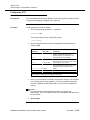
AnyMedia ConnectReach Terminal Preconfiguration Worksheet (Continued)
12.
Voice Mail
Enable:
4Off
Line group:
(1...5)
4On
Note: Configuration Integration delay: (0...500...5000) ms
is required only if
Stutter tone:
4Off
4On
the LCR feature is
Periodic ring:
4Off
4On
enabled.
DTMF settings for direct prefix, ring no answer, busy no answer, forward all, unknown forward,
and message waiting indications.
Preset profile:
4 Generic 4BBS Telecom 4Panasonic TD1232
4Toshiba DK280 4 Samsung DCS
13.
Names and
Passwords
User privilege: Name: _______________Password: ________________
Additional User Access Groups: 4Voice
4Data
4Physical
4Utils
Carrier privilege: Name>HHHHHHHHHHHHHHHPassword>HHHHHHHHHHHHHHHHHH
14.
DHCP Service
Enable:
4On
4Off
First IP address in range: ____________________ (192.168.0.2)
Last IP address in range: ____________________ (192.168.0.254)
Private network: 4On
4Off
Lease time: _______ (600…7200 seconds)
DNS server IP address: _________________ (192.168.0.1)
Domain name: ______________
15.
SNMP Service
4On
Enable:
4Off
IP address of SNMP host: __________________ (0.0.0.0)
Enable messages:
Cold start
4On
4Off
Warm start
4On
4Off
Link down
4On
4Off
Link up
4On
4Off
Login failures 4On
4Off
T1 traps
4ESs
4SESs
4SEFs
4UASs
4CSSs
4PCVs
4LESs
4BESs
4DMs
4LCVs
HTTP (Web
Browser) Port:
Enable:
17.
Telnet Port:
Enable:
4'
4'
18.
Route
Default:
WAN, PVCn or Gateway IP Address: _______________
16.
Static:
Note: One default
and up to 30 static.
4
4
Port Number:_____________________________(default 80)
Port Number:_____________________________(default 23)
Network IP Address:______________________
Netmask: _____________________
WAN, PVCn or Gateway IP Address: _______________
AnyMedia ConnectReach Terminal User’s Guide, Issue 5
E7GG7
1-23
45467006078
&&
AnyMedia ConnectReach Terminal Preconfiguration Worksheet (Continued)
19.
NAT and PAT
Dynamic
Enable:
4Off
4On
Enable:
4Off
4On
Group 1
In Start IP Address ______________ Last IP Address: _______________
Out Start IP Address _____________ Last IP Address: _______________
PAT: Protocol:_______Port #:______Keyword:_______Inband IP:______
Group 2
In Start IP Address ______________ Last IP Address: _______________
Out Start IP Address ____________ Last IP Address: _______________
PAT: Protocol:_______Port #:______Keyword:_______Inband IP:______
Group 3
In Start IP Address ______________ Last IP Address: _______________
Out Start IP Address _____________ Last IP Address: _______________
PAT: Protocol:_______Port #:______Keyword:_______Inband IP:______
Group 4
In Start IP Address ______________ Last IP Address: _______________
Out Start IP Address _____________ Last IP Address: _______________
PAT: Protocol:_______Port #:______Keyword:_______Inband IP:______
Static
Enable:
4Off
Group 1
In Start IP Address ______________ Last IP Address: _______________
4On
Out Start IP Address _____________ Last IP Address: _______________
Allow Inbound
Group 2
4Yes
4No
In Start IP Address ______________ Last IP Address: _______________
Out Start IP Address _____________ Last IP Address: _______________
Allow Inbound
Group 3
4Yes
4No
In Start IP Address ______________ Last IP Address: _______________
Out Start IP Address _____________ Last IP Address: _______________
Allow Inbound
Group 4
4Yes
4No
In Start IP Address ______________ Last IP Address: _______________
Out Start IP Address _____________ Last IP Address: _______________
Allow Inbound
Pass Thru
Enable:
4Off
4Yes
4No
4On
In Range: _____________________ to ____________________
20.
21.
ARP Configuration
IP Address_________________________________________
Ethernet Address___________________________________
IP Address_________________________________________
Ethernet Address___________________________________
IP Address_________________________________________
Ethernet Address___________________________________
IP Address_________________________________________
Ethernet Address___________________________________
IP Address_________________________________________
Ethernet Address___________________________________
IP Address_________________________________________
Ethernet Address___________________________________
IP Address_________________________________________
Ethernet Address___________________________________
IP Address_________________________________________
Ethernet Address___________________________________
Firewall
1-24 E7GG7
Standard:
4IP Filter
4IP Filter/server
Custom:
(See Appendix C, Custom Firewall Configurations for
custom IP firewall configuration.)
AnyMedia ConnectReach Terminal User’s Guide, Issue 5
45467006078
&&
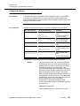
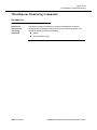
AnyMedia ConnectReach Terminal Preconfiguration Worksheet (Continued)
22.
NTP
4On
Enable:
4Off
Host name or IP address: ________________
Difference in minutes between local time and Greenwich Mean Time (GMT): ___________
23.
4On
DNS Proxy Service Enable:
4Off
IP address of primary DNS server: ____________________
IP address of secondary DNS server: ____________________
24
.
QoS
Enable:
4On
First QoS
Source IP Address
_________________
Source Netmask
___________________
Destination IP Address
______________
Destination Netmask
________________
Source IP Address
_________________
Source Netmask
___________________
Destination IP Address
______________
Destination Netmask
________________
Source IP Address
_________________
Source Netmask
___________________
Destination IP Address
______________
Destination Netmask
________________
Source IP Address
_________________
Source Netmask
___________________
Destination IP Address
______________
Destination Netmask
________________
Source IP Address
_________________
Source Netmask
___________________
Destination IP Address
______________
Destination Netmask
________________
and/or
Second QoS
and/or
Third QoS
and/or
Fourth QoS
and/or
Fifth QoS
and/or
25.
RS-232 Port
26.
SYSLOG
Baud rate:
4On
4Off
49600 (This is the default and recommended setting.)
419200
438400
4Off
IP add/name of source:
IP Address of Host:
sysconf facility 4(User-level msgs) access facility 4(Security/Authorization msgs)
* Duplicate and fill in this numbered item of the worksheet for each set of channels requiring different configuration.
AnyMedia ConnectReach Terminal User’s Guide, Issue 5
E7GG7
1-25
45467006078
&&
1-26 E7GG7
AnyMedia ConnectReach Terminal User’s Guide, Issue 5
Configuring the ConnectReach
Terminal
2
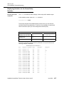
Contents
page
About This Chapter
3
Introduction
2-3
2-3
Preparing the ConnectReach Terminal for Initial Configuration
2-4
3
Equipment Required to Set Up the ConnectReach Terminal
2-4
3
Making Connections to the ConnectReach Terminal
2-5
3
Initiating a Session with the ConnectReach Terminal
2-9
3
Using the ConnectReach Terminal Utility
2-10
Using the Configuration Commands
2-13
3
Basic Procedure For Using the Configuration Commands
2-13
3
Configuring the Network T1/DSX-1 Interface
2-17
3
Configuring the Secondary/Fractional T1/DSX-1 Interface
2-20
3
Configuring DS0 Provisioning
2-23
3
Configuring the Synchronous Interface
2-28
3
Configuring the Ethernet Interface
2-35
3
Configuring the Channel Bank Mode
2-37
AnyMedia ConnectReach Terminal User’s Guide, Issue 5
E7GG7
2-1
45467006078
page
3
Configuring Digital Trunks
2-44
3
Configuring Analog Trunks
2-50
3
Configuring Lines
2-55
3
Configuring Extensions
2-66
3
Configuring Dialing
2-68
3
Configuring Voice Mail
2-75
3
Configuring Passwords
2-79
3
Configuring the DHCP Service
2-82
3
Configuring the SNMP Service
2-84
3
Configuring Routes
2-87
3
Using ARP
2-91
3
Configuring the Default Firewall
2-93
3
Configuring NAT and PAT
2-101
3
Configuring NTP
2-107
3
Configuring the DNS Server
2-108
3
Configuring the RS-232 Interface
2-109
3
Configuring QOS
2-111
3
Configuring SYSLOG
2-115
3
Configuring FTP Log Dump
2-121
3
Setting Features
2-122
3
Using Template Archive
2-124
3
Displaying Current Configuration Settings
2-126
3
Setting All Configuration Settings to Default
2-127
Reconfiguring the ConnectReach Terminal
2-128
3
2-2 E7GG7
Session Choices for Accomplishing Reconfiguration
2-128
AnyMedia ConnectReach Terminal User’s Guide, Issue 5
45467006078
About This Chapter
Introduction
Contents
This chapter provides the procedures for setting up and configuring the
ConnectReach Terminal in a staging area prior to installation. This chapter also
includes information that can be used to reconfigure the ConnectReach Terminal
system remotely after it has been installed.
AnyMedia ConnectReach Terminal User’s Guide, Issue 5
E7GG7
2-3
45467006078
Preparing the ConnectReach Terminal for
Initial Configuration
Equipment Required to Set Up the
ConnectReach Terminal
List of required
equipment
In order to initially configure the ConnectReach Terminal, you will need the
following components and equipment:
3
A ConnectReach Terminal system unit with a 120 V AC power supply
transformer and power cord or a DC power cord.
3
A computer equipped with a terminal emulation application for null modem
or dial up modem connections. This can be an IBM-compatible personal
computer (PC) running an application such as HyperTerminal, or a UNIX
workstation running tip, or any computer running a similar application. The
Telnet application is used for Ethernet connections.
3
A connection between the ConnectReach Terminal and a computer
terminal that can be accomplished in one of the three following ways:
— A modem and cable for remote connection.
— A null modem cable to connect to the serial port of a local computer
terminal. For information about the pin assignments on the RS-232
connector, refer to Chapter 3, Installation.
— An Ethernet cross-over cable to connect to the Ethernet port on a
computer equipped with an Ethernet card (required only when a PC
is being connected to ConnectReach Terminal 10BaseT port). The
ConnectReach Terminal Ethernet port operates in half-duplex
transmission mode.
3
If the ConnectReach Terminal is being configured from the GSI at the
AnyMedia Access System, the following connections must be made:
— The DS1 connection must be made at the ConnectReach Terminal
NETWORK T1 port
— GSI must be connected to the AnyMedia Access System.
2-4 E7GG7
AnyMedia ConnectReach Terminal User’s Guide, Issue 5
45467006078
Making Connections to the
ConnectReach Terminal
Introduction
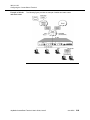
There are four ways to obtain initial access to the ConnectReach Terminal in order
to perform configuration procedures:
3
Connect a computer directly to the RS-232 port on the ConnectReach
Terminal using a null modem cable.
3
Connect a modem to the RS-232 port on the ConnectReach Terminal using
a standard serial cable and then dial up that modem from a remote
computer.
The default settings to use for the connection at the RS-232 port are as
follows:
— 9,600 baud
— Eight data bits
— One stop bit
— No parity
— Hardware flow control.
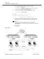
3
Connect a computer, running the CTRM terminal emulator software, or an
American standard code for information interchange (ASCII) terminal to the
GSI at the AnyMedia Access System and access the ConnectReach
Terminal by means of the T1 network interface. Refer to the AnyMedia®
Access System, Commands and Procedures, TU-830 Verify Operations Data
Link.
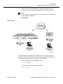
3
Connect a computer directly to the 10BaseT (Ethernet) port on the
ConnectReach Terminal using an Ethernet cross-over cable. For this
connection, the computer must have a network interface card installed. The
default IP address setting for the ConnectReach Terminal Ethernet
connection is 192.168.0.1 with a subnet mask of 255.255.255.0. The IP
address and netmask for the TCP/IP protocol of the network interface card
should be set at 192.168.0.2 and 255.255.255.0, respectively.
Once the computer has been configured with the correct IP address to
enable it to communicate with the ConnectReach Terminal Ethernet
interface, the ConnectReach Terminal supports the following sessions:
— A Telnet session over the Ethernet using a Telnet application. Once
the Telnet session is initiated, the user interface is identical to the
console session.
— A hypertext transfer protocol (HTTP) session using the Ethernet
interface and a Web browser.
AnyMedia ConnectReach Terminal User’s Guide, Issue 5
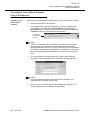
E7GG7
2-5
45467006078
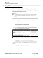
Connection at the
RS-232 port
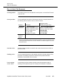
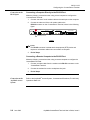
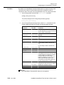
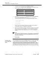
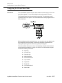
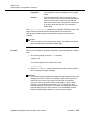
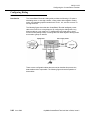
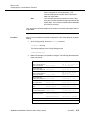
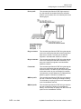
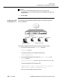
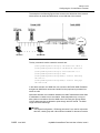
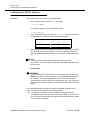
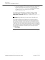
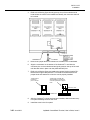
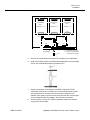
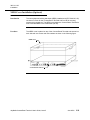
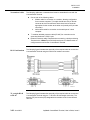
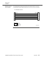
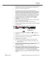
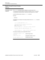
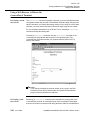
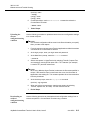
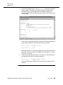
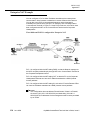
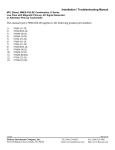
Connecting a Computer Directly to the RS-232 Port
Make the following connections when using a local computer to configure the
ConnectReach Terminal:
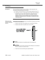
1.
Connect one end of a null modem cable to the serial port on the computer.
2.
Connect the other end of the null modem cable to the
RS-232 connector on the ConnectReach Terminal, shown in the following
figure:
ConnectReach™
RS-232
NETWORK T1
10BASE - T
STATUS
SECONDARY T1
LINE
LINE
MONITOR
VOICE CHANNELS
POWER
T1 STATUS FRAMING
MAINT. T1 STATUS FRAMING
TX RX
DTE
RS-232 DTE connector
T1/DSX-1
NOTE:
The RS-232 connector is a data terminal equipment (DTE) device and
requires a null modem cable when connected to a computer.
3.
End of Steps.
Connecting a Remote Computer to the RS-232 Port
Make the following connections when using a remote computer to configure the
ConnectReach Terminal:
Connection at the
AnyMedia Access
System
2-6 E7GG7
1.
Connect a modem cable from the modem to the RS-232 connector on the
ConnectReach Terminal.
2.
Connect the modem line cord to a telephone line jack.
3.
End of Steps.
Refer to the AnyMedia® Access System, Commands and Procedures, TU-830 Verify
Operations Data Link.
AnyMedia ConnectReach Terminal User’s Guide, Issue 5
45467006078
Connection at the
10BaseT (Ethernet)
port
Make the following connections when using a local computer to configure the
ConnectReach Terminal:
1.
Connect one end of a crossover cable to the 10BaseT (Ethernet)
connector on the ConnectReach Terminal, shown in the following figure.
ConnectReach™
RS-232
NETWORK T1
10BASE - T
STATUS
SECONDARY T1
LINE
LINE
MONITOR
VOICE CHANNELS
POWER
T1 STATUS FRAMING
MAINT. T1 STATUS FRAMING
TX RX
DTE
10BASE-T (Ethernet) connector
T1/DSX-1
Power connection
2.
Connect the other end of the crossover cable to a network interface card
on the computer.
3.
Set the Internet protocol (IP) address and netmask for transport control
protocol/Internet protocol (TCP/IP) of the network interface card using the
following example:
IP address: 192.168.0.2
netmask: 255.255.255.0
4.
End of Steps.
The ConnectReach Terminal can be powered by either a 120 V AC power supply
transformer or from a 48-volt power source such as central office (CO) battery or
an approved DC battery backup unit. For more information about the power
requirements for the ConnectReach Terminal, refer to Chapter 3, Installation. Make
power connections to the ConnectReach Terminal as follows:
1.
Plug in the power cable from the power supply source into the POWER
connector on the ConnectReach Terminal. The location of the POWER
connector is shown in the following figure:
ConnectReach™
RS-232
STATUS
NETWORK T1
10BASE - T
SECONDARY T1
LINE
LINE
MONITOR
VOICE CHANNELS
POWER
T1 STATUS FRAMING
MAINT. T1 STATUS FRAMING
TX RX
DTE
POWER connector
T1/DSX-1
2.
Position the power cable connector so that the locking ramp is toward the
top of the ConnectReach Terminal, as shown in the following figure:
Position locking ramp
towards top of unit.
3.
Plug in the AC power supply transformer into a 120 V AC receptacle or turn
on the circuit breaker switch as appropriate.
AnyMedia ConnectReach Terminal User’s Guide, Issue 5
E7GG7
2-7
45467006078
4.
Observe the light emitting diodes (LEDs) on the ConnectReach Terminal to
verify that the unit is starting up successfully.
Requirement: The STATUS, NETWORK T1 - T1 STATUS,
and NETWORK T1 - FRAMING LEDS are lighted.
5.
2-8 E7GG7
End of Steps.
AnyMedia ConnectReach Terminal User’s Guide, Issue 5
45467006078
Initiating a Session with the
ConnectReach Terminal
From a computer
connected to
RS-232 port
After you have connected a computer or modem to the ConnectReach Terminal,
start a serial terminal emulation application to initiate a communications session.
For example, you can start an application such as tip on a UNIX workstation, or
HyperTerminal on Microsoft Windows.
From the GSI or
terminal of the
AnyMedia Access
System
Refer to the AnyMedia® Access System, Commands and Procedures, TU-830 Verify
Operations Data Link to initiate a session with the ConnectReach Terminal.
AnyMedia ConnectReach Terminal User’s Guide, Issue 5
E7GG7
2-9
45467006078
Using the ConnectReach Terminal Utility
Description
After the computer terminal is connected to the ConnectReach Terminal using a
terminal emulation application, the ConnectReach Terminal activates the utility
program which allows the computer to communicate with the ConnectReach
Terminal to issue commands and receive messages from the ConnectReach
Terminal. During start-up, the utility causes a series of session start-up messages
and a command prompt to appear in the console window. This prompt, a greaterthan symbol ( > ), is the ConnectReach Terminal Utility Main Menu prompt, as
shown in the following figure.
NOTE:
These messages are not displayed if the power was applied before the
terminal program was started. The Main Menu prompt ( > ) will be the only
thing appearing on the screen. To display these messages, enter the
version command.
NOTE:
The following screen display is only an example of what may appear on
your console window. The actual display will depend on the version of
software in the ConnectReach Terminal. Refer to the appropriate software
release description for additional information.
Entering commands
At the Main Menu prompt, you can enter a set of commands called the Main Menu
commands.
These commands are not case sensitive. You can abbreviate a command to the
minimum number of characters that uniquely identify the command. For example,
you can enter the configure command by typing the first four characters:
> conf
2-10 E7GG7
AnyMedia ConnectReach Terminal User’s Guide, Issue 5
45467006078
After you enter a command, the ConnectReach Terminal Utility either executes the
command or displays a submenu command prompt. For example, if you enter the
configure command, the Config submenu prompt appears:
(config) >
At the Config prompt, you can enter the commands to configure specific sets of
commands. Each set has its own submenu, where a new prompt is displayed. For
example, when you enter the command to configure the Ethernet interface, the
prompt changes to:
(config:Ethernet)>
After completing the configuration for each component, you return to the Config
menu by entering the exit command or, if you are not entering commands from
the AnyMedia Access System GSI, by typing an exclamation point ( ! ).
Getting online help
At any time, you can display a list of the commands in the current menu by typing
a question mark (?). If you enter a question mark after partially typing a command,
the options for that specific command are displayed. Otherwise, a list of the
currently available commands is displayed. The default settings are enclosed in
brackets.
In addition to the question mark, each menu has a help command. The help
command displays a brief explanation of each command on the current menu.
Exiting the Utility
When you are finished configuring the ConnectReach Terminal, you should exit the
Utility by using the exit command at the Main Menu prompt.
The ConnectReach Terminal Utility allows only one management session at a time.
Exiting the Utility allows another administrator to connect to the ConnectReach
Terminal and configure or monitor it.
A ConnectReach Terminal management session can override another session in
the following ways:
3
If another session is already in progress, and you start a new session, you
will be notified that another user is logged in and asked whether you wish
to override that user.
3
If you have a management session in progress, and another administrator
overrides your session, you will be notified that your session has been
overridden.
AnyMedia ConnectReach Terminal User’s Guide, Issue 5
E7GG7
2-11
45467006078
Using the Main
Menu commands
The following table lists the commands available at the Main Menu prompt.
To…
Enter this command…
Display Online Help for the commands currently
available
? (question mark)
Configure the ConnectReach Terminal
config
Display statistics about the ConnectReach Terminal
statistics
Upgrade the ConnectReach Terminal with new software
using the network
network-upgrade
Upgrade the ConnectReach Terminal with new software
using a modem
xmodem-download
Save the current configuration or retrieve a
configuration from a remote computer
archive
Display version and uptime information
version
Show the hardware configuration
show-hardware-config
View a log of events
log
Set an analog voice channel to a known state for testing diagnose
2-12 E7GG7
Check that a device is communicating on the network
ping
Trace the route between two points on the network
traceroute
Reboot the ConnectReach Terminal. Existing voice calls
are dropped if T1 feeder is TR-303.
warm-start
Reboot the ConnectReach Terminal with interruptions of
both voice and data connections
cold-start
Reboot the ConnectReach Terminal Slave with minimal
interruption of existing voice connections
slave-warm-start
Reboot the ConnectReach Terminal Slave with
interruptions of both voice and data connections
slave-cold-start
Get online assistance
Help
Exit the ConnectReach Terminal Utility and disconnect
from the ConnectReach Terminal
exit
AnyMedia ConnectReach Terminal User’s Guide, Issue 5
45467006078
Using the Configuration Commands
Basic Procedure For Using the
Configuration Commands
Introduction
A list of all configuration menu commands is given in the following table.The
command(s) associated with a particular feature will appear only if that feature is
available (activated).
To…
Enter this command…
Configure the Network T1/DSX-1 interface to the carrier CO
Network-t1
Configure the Secondary T1/DSX-1 or Fractional T1/DSX-1
interface
Secondary-t1 or
Fractional-t1
Specify the split between voice and data T1 DS0s
DS0-Provisioning
Configure the synchronous interface
Synchronous-interface
Configure the Ethernet interface to the local area network (LAN) Ethernet
Configure telephony functionality for channel-bank mode
Channel-bank
Configure digital trunks
Digital-trunk
Configure analog trunks
Analog-trunk
Configure lines
Line
Configure (Map) Line Extensions
Map-Extensions
Configure dialing
Dialing
Configure attached Voice Mail System
Voice-Mail
Configure user names and passwords
Passwords
Configure the Internet protocol (IP) address allocation service
DHCP
Configure the simple network management protocol (SNMP)
service
SNMP
Configure a Telnet port
Telnet
Configure a Web browser port
HTTP
Configure the default route(s)
Route
Set or clear MAC/IP address mapping
ARP
Configure Firewall support
FIREWALL
Configure network address translation (NAT)
NAT
Configure network time protocol (NTP)
NTP
Configure domain name service (DNS)
DNS
Configure the RS-232 port
RS232
Configure syslog monitoring facility
syslog
Configure IP quality of service (QOS)
qos
Configure log on for file transfer protocol (FTP) download
Ftp-log-dump
AnyMedia ConnectReach Terminal User’s Guide, Issue 5
E7GG7
2-13
45467006078
To…
Enter this command…
Using template archive
template-archive
Display features
features-show
Set features
set-features
Show all configuration settings
show
Save the configuration settings in the ConnectReach Terminal
save
Set all configuration commands to their default values
default
Set all configuration commands to their default values, retaining
the Ethernet, password, and RS232 commands
preserve-default
Access online assistance
Help
Exit the Config prompt and return to the Main Menu prompt
exit
Every configuration command has default settings, including IP addresses. The
default settings for each configuration command are displayed on screen in
brackets after you enter a question mark ( ? ) at the Config prompt.
Basic steps in
configuring and
saving new settings
The following steps provide the basic procedure for entering configure commands
and saving the configuration settings:
1.
At the Main Menu prompt, enter the configure command.
config
2.
Press the ENTER key and the prompt changes to the Config prompt where
you can enter the Configuration commands.
(config)>
3.
At the Config prompt, enter the appropriate Configuration commands or
type a question mark (?) for a list of all available commands.
4.
After you use the configuration commands, you must save your
configuration settings in nonvolatile random access memory (NVRAM). To
save the configuration settings, enter the save command at the Config
prompt.
(config)> save
NOTE:
If you do not wish to save the configuration settings that you have entered,
you can discard them by using the exit command, explained in the next
step, instead of the save command.
5.
2-14 E7GG7
Enter the exit command: (config)> exit
You will receive a prompt:
Do you really want to abandon your changes? [n]y:
Type y to save the original configuration.
AnyMedia ConnectReach Terminal User’s Guide, Issue 5
45467006078
6.
Activating new
configuration
settings
End of steps.
Some commands are activated and take effect as soon as you enter the save
command, but others require that you reboot the ConnectReach Terminal, using
either the warm-start or cold-start command, before the new settings take
effect. The following table indicates which commands require a reboot to take
effect and which type of reboot is required.
Commands Requiring the Save Command to Take Effect:
Analog Trunk
Channel Bank
Dialing
Digital Trunk
DS0-Provisioning* (all commands except Ethernet (all commands except IP or
ConnectReach and Analog-begin)
secondary-IP)
Firewall
Lines
Map-Extensions
NAT/PAT
NTP
Password
QOS
RS-232
SNMP (all commands except enable on/
off and changing SNMP-host)
Synchronous-Interface: changing IP
addressing
SYSLOG
Voice-Mail
template-archive
Commands Requiring the Save and Warm-Start Commands to Take Effect:
Default
DHCP
DNS (enable on/off)
Ethernet (IP and
secondary-IP)
Network-T1 Other
than Clock
Preserve-Default
Route
Secondary-T1 or
Fractional-T1
Set-Features
Synchronous-Interface: all commands except IP addressing
Commands Requiring the Save and Cold-Start Commands to Take Effect:
ARP
ConnectReach
DS0-Provisioning:
Modify Analog-begin HTTP Port
Cross-connect (channel-bank submenu);
Network-T1 Clock
SNMP (enabling/
disabling, changing
host)
Telnet Port
To reboot the ConnectReach Terminal, enter the appropriate command at the Main
Menu prompt:
> warm-start
or
> cold-start
AnyMedia ConnectReach Terminal User’s Guide, Issue 5
E7GG7
2-15
45467006078
NOTE:
Rebooting a ConnectReach Terminal fed by a TR-303 T1 line using the
warm-start command drops all existing calls.
Rebooting the ConnectReach Terminal with the cold-start command
interrupts both voice and data connections. All connections are lost. New
connections cannot be made for up to 60 seconds.
If you set up login names during the initial configuration, when the ConnectReach
Terminal reboots, the Utility prompts you to enter a login name and password.
Information about login names is presented later in this chapter.
Archiving
configuration
settings
In the event that the ConnectReach Terminal loses the configuration settings stored
in nonvolatile random access memory (NVRAM), it is suggested that the
configuration information be stored (archived) in a remote computer so that the
information can be restored without having to enter all of it again.
The archive command, located in the Main Menu, is used to upload the
configuration settings to a remote computer and download the saved
configuration settings from the remote computer. The archive command also
allows you to download identical or nearly identical settings to multiple
ConnectReach Terminal units from a remote computer.
For more information concerning the use of the archive command to upload and
download configuration settings from a remote computer, refer to Chapter 6,
Software Upgrade, Maintenance, and Trouble Clearing.
2-16 E7GG7
AnyMedia ConnectReach Terminal User’s Guide, Issue 5
45467006078
Configuring the Network T1/DSX-1
Interface
Introduction
Before configuring the Network T1/DSX-1 interface of the ConnectReach Terminal,
you must determine how the DS1 signal on the network carrier facility has been
configured by the carrier.
Key commands
The key commands that must match the carrier’s configuration are as follows:
Framing Format
The ConnectReach Terminal offers the two most
common T1 framing formats: Extended Superframe
(ESF) and Superframe (SF or D4). However, the ESF
framing format should always be selected to assure
compatibility with the AnyMedia Access System.
Line Coding
The T1 line coding formats offered by the
ConnectReach Terminal are bipolar 8 zero substitution
(B8ZS) and alternate mark inversion (AMI). However,
the B8ZS line coding format should always be
selected to assure compatibility with the AnyMedia
Access System. T1 line coding determines how the T1
requirement for ones density is handled. In every eight
bits of information, at least one pulse must be present.
Line Buildout
T1 line buildout is configurable to 0 dB, –7.5 dB,
–15 dB, or –22 dB, as required by Federal
Communications Commission (FCC) Part 68. Buildout
sets the ConnectReach Terminal’s output T1
transmission signal level (0 dB is the highest level and
–22.5 dB is the lowest level). The default, 0 dB, is the
most common signal level for connection to the carrier.
If line buildout is set incorrectly, the carrier may detect
errors ranging from bipolar violations (line buildout too
high) to loss of signal (line buildout too low).
Clock Source
Always select network.
Pulse Density
Enforcement
Alarm Operation
This option is used when AMI line coding is selected
(see the description of line coding presented earlier).
Per the AT&T TR-62411 ACCUNET specification, bit
stuffing must be enabled when AMI line coding is
selected. This ensures that ones density requirements
are met (see ANSI standard T1.403, paragraph 5.6).
This option controls whether the network T1 going
down causes the alarm relay to close.
AnyMedia ConnectReach Terminal User’s Guide, Issue 5
E7GG7
2-17
45467006078
Procedure
Alarm Delay
This option sets the delay between when the T1 alarm
is cleared and the relay returns to an unalarmed state.
For example, if the delay is set for 15 seconds, the
alarm relay will go from alarm to no alarm 15 seconds
after the T1 alarm clears.
Is Slave
This option designates one of the two ConnectReach
systems in a 48-line master/slave configuration as the
slave unit. Refer to Chapter 3, Installation for details
on the 48-line master/slave configuration.
After you have determined the carrier’s configuration, follow these steps to
configure the network T1/DSX-1 interface:
1.
At the Config prompt, enter the network-t1 command:
(config)> network-t1
The prompt changes to the Config:Network T1 prompt.
(config:Network-t1)
2.
At the Config:Network T1 prompt, enter the appropriate commands from
the following table. The default setting for each command appears in
brackets:.
To
Enter this
command...
...and one of these
options
Enable Network T1/DSX-1
enable
off, [on]
Set the framing format
framing
[ESF], D4
Set the line coding format
linecode
[B8ZS], AMI
Set the build out in feet or decibels * buildout
[0-133ft(DSX)/
0dB(CSU)],
133-266ft(DSX),
266-399ft(DSX),
399-533ft(DSX),
533-655ft(DSX),
– 7.5dB(CSU),
–15dB(CSU),
-22.5dB(CSU)
Set the clock source (this option only
available if internal clock exists)
clock
[network], internal
Comply with ones density
specification (applies only to AMI line pulse-densitycoding)
enforce
[off], on
If set to on, an alarm on Network T1/
DSX-1 will cause the alarm relay to
close
alarm-operation off, [on]
Sets the delay between a Network
T1/DSX-1 alarm and closing of the
alarm relay
2-18 E7GG7
alarm-delay
0..[15]..3600 sec
AnyMedia ConnectReach Terminal User’s Guide, Issue 5
45467006078
To
Enter this
command...
Set the ConnectReach Terminal as a
slave to another ConnectReach
Terminal (allows for 25-48 ports for
voice only) †
is-slave
Access online assistance
...and one of these
options
[off], on
Help
* The line buildout command may be specified for connection to a channel service unit
(CSU) or to a digital signal cross-connect (DSX). For a CSU, the value is specified in
decibels (dB); for a DSX, the value is specified in feet.
I
J
All of the channel units for the DS0-Provisioning:ConnectReach command must also be
set to none to allow for a slave.
This command is not used in the ConnectReach Terminal
3.
When you have made the necessary configuration changes, you can return
to the Config menu by typing exit or, if you are not entering commands
from the AnyMedia Access System GSI, you can enter an exclamation
point (!).
4.
End of Steps.
AnyMedia ConnectReach Terminal User’s Guide, Issue 5
E7GG7
2-19
45467006078
Configuring the Secondary/Fractional T1/
DSX-1 Interface
Introduction
A secondary/fractional T1/DSX-1 interface can be used to connect the
ConnectReach Terminal to a voice or data system by means of a fractional
daughter card. The secondary/fractional T1/DSX-1 interface can also be used to
connect another ConnectReach Terminal as a slave to support up to 24 additional
lines. Examples of voice systems are key system, PBX, or channel bank. A data
system is connected by means of a CSU/DSU and a router.
If the secondary/fractional T1/DSX-1 interface will be used to connect the
ConnectReach Terminal to the telephone system, you must determine how the T1
service has been configured in the PBX or key system.
Key commands
2-20 E7GG7
The key commands that must match the PBX or key system’s configuration are as
follows:
Framing Format
The ConnectReach Terminal offers the two most
common T1 framing formats: Extended Superframe
(ESF) and Superframe (SF or D4). However, the ESF
framing format should always be selected to assure
compatibility with the equipment connected to the
secondary/fractional T1 port.
Line Coding
The T1 line coding formats offered by the
ConnectReach Terminal are bipolar 8 zero substitution
(B8ZS) and alternate mark inversion (AMI). However,
the B8ZS line coding format should always be
selected to assure compatibility with the equipment
connected to the secondary/fractional T1 port. T1 line
coding determines how the T1 requirement for ones
density is handled. In every eight bits of information, at
least one pulse must be present. If the T1 service uses
AMI line coding, it is important to enable the pulse
density enforcement option (see below). If the T1
service uses B8ZS line coding, a bipolar violation
(BPV) is automatically inserted in place of a string of
eight zeros during transmission. At the receiver, the
original data stream is regenerated as a result of the
BPV. In this configuration, the pulse density
enforcement option is ignored.
Line Buildout
T1 line buildout is configurable to 0 dB, –7.5 dB
–15 dB, or –22 dB, as required by FCC Part 68.
Buildout sets the ConnectReach Terminal’s output T1
transmission signal level (0 dB is the highest level and
-15 dB is the lowest level). The default, 0 dB, is the
most common signal level for connection to the carrier.
AnyMedia ConnectReach Terminal User’s Guide, Issue 5
45467006078
If line buildout is set incorrectly, the carrier may detect
errors ranging from bipolar violations (line buildout too
high) to loss of signal (line buildout too low).
Pulse Density
Enforcement
Procedure
This option is used when AMI line coding is selected
(see the description of line coding presented earlier).
Per the AT&T TR-62411 ACCUNET specification, bit
stuffing must be enabled when AMI line coding is
selected. This ensures that ones density requirements
are met (see ANSI standard T1.403, paragraph 5.6).
Alarm Operation
This option controls whether the secondary/fractional
T1/DSX-1 going down causes the alarm relay to close.
Refer to Chapter 6, Software Upgrade, Maintenance,
and Trouble Clearing, for more information.
Alarm Delay
This option sets the delay between the
secondary/fractional T1/DSX-1 alarm and the closing
of the alarm relay.
Has Slave
This option allows the ConnectReach Terminal to serve
as the master unit in a 48-line master/slave
configuration. Refer to Chapter 3, Installation for
details on the 48-line master/slave configuration. The
clock source for the secondary/fractional T1/DSX-1 is
always internal, synchronous to the network T1/DSX1.
After you have verified the required configuration, follow these steps to configure
the secondary T1/DSX-1 interface for the ConnectReach Terminal
1.
At the Config prompt, enter the secondary-t1 (T1/DSX-1 interface) or
fractional-T1 command:
(config)> secondary-t1 or (config)> fractional-t1
(config:Secondary-t1)> or (config:Fractional-t1)
2.
At the Config:Secondary/Fractional T1 prompt, enter the appropriate
commands from the following table. The default setting for each command
appears in brackets:
To
Enter this
command... ...and one of these options
Enable secondary/fractional
T1/DSX-1
On, [Off]
Set the framing format
[ESF], D4
Set the line coding format
[B8ZS], AMI
AnyMedia ConnectReach Terminal User’s Guide, Issue 5
E7GG7
2-21
45467006078
Enter this
command... ...and one of these options
To
Set the build out in feet or
decibels *
Comply with ones density
specification (applies only to
AMI line coding format)
66
On, [Off]
Enables the alarm operation
6
[off], on
Sets the delay between a
secondary/fractional T1/DSX1 alarm and closing of the
alarm relay.
6
0..[15]..3600 sec
Set the secondary/fractional
T1/DSX-1 to accept a slave
from another ConnectReach
Terminal (allows for 25-48
ports for voice only).
6$
[off], on
Access online assistance
,
K
3.
[0-133ft(DSX)/
0dB(CSU)],
133-266ft(DSX),
266-399ft(DSX),
399-533ft(DSX),
533-655ft(DSX),
–7.5dB(CSU), –
15dB(CSU),
–22.5dB(CSU)
The line buildout command may be specified for connection to a CSU or to a
DSX. For a CSU, the value is specified in decibels (dB); for a DSX, the value is
specified in feet.
When you have made the necessary configuration changes, you can return
to the Config menu by typing exit or, if you are not entering commands
from the AnyMedia Access System GSI, you can enter an exclamation
point (!).
NOTE:
If you change any of these commands, you must save the configuration and
reboot the ConnectReach Terminal using the warm-start command for the
new settings to take effect.
4.
2-22 E7GG7
End of Steps.
AnyMedia ConnectReach Terminal User’s Guide, Issue 5
45467006078
Configuring DS0 Provisioning
Introduction
A T1 consists of 24 time-division multiplexed channels, which are called DS0s.
The DS0 provisioning menu maps ranges of DS0s to any of these destinations:
Analog
Voice (DS0s) to analog (FXS and FXO) ports
Data
Data (DS0s) for Ethernet hosts or for the
ConnectReach Terminal’s internal router
Secondary/Fractional
T1/DSX-1 voice
Secondary/Fractional
T1/DSX-1 data
Alignment of Secondary/
Fractional T1/DSX-1
ConnectReach
Voice (DS0s) for a PBX or channel bank
connected to the Secondary/Fractional T1/DSX-1
interface
Transparent data (DS0s) for a CSU/router
connected to the Secondary/Fractional T1/DSX-1
interface
The two options are as follows:
1. The DS0s on the Network T1/DSX-1 can be
connected to the same DS0 numbers on the
Secondary/Fractional T1/DSX-1.
2. The lowest numbered DS0 on the Network T1/
DSX-1 that is assigned to the Secondary/
Fractional T1/DSX-1 port can be connected to the
first DS0 on the Secondary/Fractional T1/DSX-1.
If the lowest numbered DS0 option is used with
the Secondary/Fractional T1/DSX-1 port and
analog ports are enabled, a fractional T1/digital
signal processor (DSP) combination circuit card is
required.
Channel unit assignment to DS0 channels and
change of status of the ClearReach™ feature.
NOTE:
Secondary/Fractional T1/DSX-1 voice uses robbed bit signaling (RBS),
which is the common method of transporting voice over T1. Secondary/
Fractional T1/DSX-1 data does not use RBS.
NOTE:
If the Alignment is set to the low option, do not begin the range of DS0s for
either Secondary Voice or Secondary Data with DS0 number 3. Beginning
the range with DS0-3 will cause a failure of the bit error rate (BER) test.
AnyMedia ConnectReach Terminal User’s Guide, Issue 5
E7GG7
2-23
45467006078
Procedure
By default, the ConnectReach Terminal software sets the number of analog voice
channels to the number of actual analog ports that are installed. It sets no
channels for data. The range of the four destinations may not overlap each other
1.
At the Config prompt, enter the DS0-provisioning command:
(config)> DS0-provisioning
The prompt changes to the Config:DS0-provisioning prompt.
(config:DS0-provisioning)>
2.
At the Config:DS0-provisioning prompt, enter the DS0 command from the
following table and specify the ranges of analog and data channels:
Enter this
command...
...and specify
the value
Comments
analog-begin
[n] 0...24
Software automatically detects the number
of voice channels. If no voice channels are
found, a value of 0 is entered.
analog-end
[n] 0...24
Sets value to the last voice channel
detected.
sec-voice-begin
[0] 0...24
For secondary T1/DSX-1 interface use
only.
sec-voice-end
[0] 0...24
For secondary T1/DSX-1 interface use
only.
sec-data-begin
[0] 0...24
For secondary T1/DSX-1 interface use
only.
sec-data-end
[0] 0...24
For secondary T1/DSX-1 interface use
only.
data-begin
[0] 0...24
data-end
[0] 0...24
If set to the default value, low, the
ConnectReach Terminal connects the lowest
numbered DS0 on the Network T1/DSX-1
to the first DS0 on the Secondary/
Fractional T1/DSX-1. If set to same, the
DS0s on the Network T1/DSX-1 are
connected to the same DS0 numbers on
the Secondary/Fractional T1/DSX-1.
alignment-sec-t1
[low] same
ConnectReach
Allows available channel units to be
DS0 range CU designated for DS0 channels and enables/
disables the ClearReach feature.
ClearReach
Help
Access online assistance.
NOTE:
The ConnectReach Terminal HDSL feature is not supported.
2-24 E7GG7
AnyMedia ConnectReach Terminal User’s Guide, Issue 5
45467006078
3.
Assign available channel unit types to designated DS0 channels and, if
necessary, enable/disable the ClearReach feature using the
ConnectReach command.
NOTE:
Provisioning of the ConnectReach Terminal channel unit types is defaulted
according to the hardware configuration of the system (FXS and FXO
cards). If a 452 data channel unit type or 443 channel unit type is to be used
for the data channels or the foreign exchange lines, respectively, then it
must be provisioned using the ConnectReach command.
NOTE:
The ConnectReach command must be executed before saving other DS0
provisioning values or a confirmation error message may be displayed.
4.
When you have made the necessary configuration changes, you can return
to the Config menu by typing exit or, if you are not entering commands
from the AnyMedia Access System GSI, you can enter an exclamation
point (!).
NOTE:
If you change the begin channel in any of the ranges while using any of the
DS0 commands, the new command values do not take effect until you save
the configuration and reboot the ConnectReach Terminal using the coldstart command. If you do not change the begin channel in any of the
ranges, the new command values take effect as soon as you save the
configuration. In this case you do not need to reboot the ConnectReach
Terminal to use the new values.
5.
Examples of
channel assignment
schemes
End of Steps.
Examples of channel assignment schemes are listed below:
3
Configure full T1 bandwidth for data as follows: set data-begin to 1,
data-end to 24, and all other values to 0 (zero).
3
Configure full T1 bandwidth for voice lines connected to the
Secondary/Fractional T1/DSX-1 connector as follows: set
sec/frac-t1-voice-begin to 1, sec/frac-t1-voice-end to 24, and all other
values to 0 (zero).
3
Configure half the T1 bandwidth for analog voice connections and
half for data as follows: set analog-begin to 1, analog-end to 12, databegin to 13, and data-end to 24.
NOTE:
There is a restriction in the same mode, that any DS0s used for analog
voice must have lower channel numbers than any DS0s used for the
Secondary/Fractional T1/DSX-1.
AnyMedia ConnectReach Terminal User’s Guide, Issue 5
E7GG7
2-25
45467006078
It is recommended that you always configure the voice channel range to start with
channel 1 and increment from there. Configure the data channel range to start
with the highest numbered channel group (21-24) and decrement from there. If
some channels are unconfigured, it will be easier to make changes later if the
unconfigured channels are between the voice range and the data range.
When the ConnectReach command is selected, the following is a sample of the
display that will appear on the terminal monitor:
1-4
: 440
([440] 443 452 456 400 none)
5-8
: 440
([440] 443 452 456 400 none)
9 -12
: 456
([440] 443 452 456 400 none)
13 -16
: none
([440] 443 452 456 400 none)
17-20
: none
([440] 443 452 456 400 none)
21-24
: 452
([440] 443 452 456 400 none)
ClearReach-enable
: off
([off] on)
Help
!
The left column in the display indicates a DS0 channel range. The middle column
shows the currently configured channel unit type. The right column shows all
possible channel unit choices, including none, with the default choice in square
brackets. In this specific example, for DS0 channels 1 through 4 and 5 through 8,
440D channel unit types are being emulated. A 456 channel unit type is emulated
for DS0 channels 9 through 12 and a 452 channel unit type is emulated for DS0
channels 21 through 24. Since DS0 channels 13 through 16 and 17 through 20
have the “none” option, no channel unit type is to be emulated in these positions.
The SPQ400 may only be provisioned in an AnyMedia ConnectReach system
operating as a secondary voice channel, and cannot provide the ClearReach
feature.
To change channel unit type assignments for a specific DS0 channel range, enter
the following command:
(config:DS0-provisioning:ConnectReach)> channel range channel unit
Example:
(config:DS0-provisioning:ConnectReach)> 1-4 443
Example of
ClearReach feature
enabling/disabling
When the ConnectReach command is selected, the display on the terminal
monitor shows a listing of the channel unit assignments, as described in
Examples of channel assignment schemes on page 2-25, and the status of the
ClearReach feature. If it is necessary to change the status of the ClearReach
feature, use the following syntax to make the appropriate change:
(config:DS0-provisioning:ConnectReach)>clearreach /
2-26 E7GG7
AnyMedia ConnectReach Terminal User’s Guide, Issue 5
45467006078
Example:
(config:DS0-provisioning:ConnectReach)>clearreach NOTE:
When the ClearReach feature is enabled in the ConnectReach terminal, the
LCR and BOX features are unavailable (disabled). When the LCR and BOX
features are enabled in the ConnectReach terminal, ClearReach is turned
off.
AnyMedia ConnectReach Terminal User’s Guide, Issue 5
E7GG7
2-27
45467006078
Configuring the Synchronous Interface
Introduction
You must specify Synchronous Interface Encapsulation for installations that use
data channels. After you specify an encapsulation method, you must also
configure the associated interface settings through the Modify-encap-data
command. For example, if you set the encapsulation to point-to-point protocol
(PPP), then you must also configure the PPP interface with the
Modify-encap-data command.
Key commands
The following key commands are available using the synchronous interface
command:
Encapsulation
Allows the selection of the encapsulation protocol to be frame
relay, PPP, or high-level data link control (HDLC).
HDLC Inversion
Enabling HDLC inversion helps the line comply with the ones
density specification. Ones density applies only if the network
T1/DSX-1 interface is configured to use AMI line coding,
regardless of the encapsulation scheme being used on the
synchronous interface.
Modify encap data Allows the selection of specific values appropriate to the
chosen encapsulation scheme.
Procedure
IP Unnumbered
The ConnectReach Terminal allows the use of “Internet
protocol (IP) unnumbered” WAN interfaces. An unnumbered
interface is an interface that does not consume a unique IP
address. This option is enabled by setting the IP-address
command to Enet, indicating that this interface is to share the
same IP address as the Ethernet interface.
RIP
For each encapsulation there are four routing information
protocol (RIP) options; Enable, RxOnly, TxOnly and Disable.
If RxOnly RIP is selected, advertisements are accepted (that
is, received). If TxOnly RIP is selected, advertisements are
sent (that is, transmitted). Setting RIP to enable activates
both transmit and receive. To turn off RIP, select disable.
1.
At the Config prompt, enter the synchronous-interface command:
(config)> synchronous-interface
The prompt changes to the Config:Synchronous-interface prompt.
(config:Synchronous-interface)
2-28 E7GG7
AnyMedia ConnectReach Terminal User’s Guide, Issue 5
45467006078
2.
To set the synchronous interface encapsulation, enter the
encapsulation command at the Config:Synchronous-interface prompt
and the appropriate setting from the following table:
Enter this command...
...and specify this setting
encapsulation
[Frame-relay], PPP, HDLC
HDLC-inversion
[off], on
modify-encap-data
Help
3.
Enter the Modify-encap-data command to specify values appropriate
to the chosen encapsulation scheme. The Modify-encap-data
command changes the prompt to the selected encapsulation scheme.
(config:Frame-relay)>
(config:PPP)>
(config:HDLC)
Refer to one of the following procedures that pertains to the selected
encapsulation scheme to complete the configuration.
4.
When you have made the necessary configuration changes, you can return
to the Config menu by typing exit or, if you are not entering commands
from the AnyMedia Access System GSI, you can enter an exclamation
point (!).
NOTE:
If you change any of these commands, you must save the configuration and
reboot the ConnectReach Terminal using the warm-start command for the
new settings to take effect.
5.
Using the frame
relay modification
menu
End of Steps.
The ConnectReach Terminal uses the standard request for comment (RFC) 1490
to send IP packets over a frame relay connection. The local management
interface (LMI)-type provides for two different signaling specifications, T1.617
(ANSI) and Q.933-annex-A [International Telecommunication Union/Consultative
Committee for International Telegraph and Telephone (ITU/CCITT)]. The frame
relay modification menu allows configuration for as many as 30 permanent virtual
AnyMedia ConnectReach Terminal User’s Guide, Issue 5
E7GG7
2-29
45467006078
circuits (PVCs). At the Config:Synchronous-interface prompt, enter the Modifyencap-data command to access the frame relay commands listed in the following
table:
Enter this
command...
...and specify this value
Comments
LMI-type
none,[T1.617-annex-D *],
Q.933-annex-A †
Specify annex type of Local
Management Interface (LMI).
N391 J
[6] 1...255
Specify the polling cycles for
status of all permanent virtual
circuits (PVCs).
N392J
[3] 1...255
Specify the threshold for the
monitored event counter.
N393J
[3] 1...10
Specify the monitored event
counter interval.
T391J
[6] 1...10
Specify the time in seconds for
LMI requests to be sent.
show-all-PVCs
Displays the configuration for all
PVCs.
Help
Access online assistance.
* This setting is sometimes referred to as Annex D or .
Configuring using
the PVC submenu
commands
I
This setting is sometimes referred to as CCITT or ITU.
J
It is recommended that you use the default values for these commands unless the carrier
specifies otherwise.
Each PVC submenu allows the user to configure Data Link Connection Identifier
(DLCI) and IP commands.
The ConnectReach Terminal’s implementation of Inverse Address Resolution
Protocol (InARP) is based on RFC 1293. It allows a router at the other end of the
Frame Relay network to discover the IP address of the ConnectReach Terminal
associated with a PVC. The ConnectReach Terminal passively responds to InARP
requests by supplying its IP address.
1.
At the Config:Frame-relay prompt, enter PVCn where n is any number from
one to five.
(config:Frame-relay)> PVC1
The prompt changes to the Config:FrameRelay:PVC1 prompt.
(config:FrameRelay:PVC1)
2-30 E7GG7
AnyMedia ConnectReach Terminal User’s Guide, Issue 5
45467006078
2.
At the Config:FrameRelay:PVC1 prompt, enter the appropriate commands
from the following table. The default setting for each command appears in
brackets.
Enter this
command...
...and specify this value Comments
DLCI
[16]...991
Enter the assigned DLCI for the
ConnectReach Terminal.
IP-address
IP-address, Enet*,
[Disable]
Enter the IP address for the
frame relay’s interface, Enet or
disable this command.
netmask
netmask
Enter a netmask value, such as
255.255.255.0.
RIP
Enable, RxOnly,
TxOnly, [Disable]
Select the mode of RIP to use.
version-RIP
[1], 2
Select the version of RIP to use.
Help
Access online assistance.
* The Enet value assigns the primary Ethernet IP address (IP unnumbered).
3.
Using the SLA
commands
End of Steps.
A service level agreement (SLA) is a contract between a carrier and a customer
that specifies a measurable level of service the carrier will provide. SLAs offer a
way to document the success of a network to meet the needs and expectations of
the user.
Minimum and maximum levels of performance, reliability, security and cost,
defined in the SLA contract are based on customer requirements as well as
service provider needs. The implementation of the SLA for the ConnectReach
Terminal includes the measurements of end-to-end latency, below Committed
Information Rate (CIR) DDR, above CIR DDR ratios and various statistics on the
PVC status. For ease of management a number of SLA SNMP traps have been
made available. The SLA implemented for the ConnectReach Terminal is
proprietary, therefore monitoring is possible between two or more ConnectReach
Terminal units connected through a Frame Relay network. SLA statistics are
stored in intervals of 15 minutes and kept for a period of 24 hours. All SLA
statistics are based on the proprietary MIB. SLA requires the activation of the SLA
feature key, see “Setting Features” on page 2-122.
1.
At the config:Frame-relay:PVCn prompt, enter SLA.
(config:Frame-relay:PVC1)> SLA
The prompt changes to the config:FrameRelay:PVC1:SLA prompt.
(config:FrameRelay:PVC1:SLA)>
AnyMedia ConnectReach Terminal User’s Guide, Issue 5
E7GG7
2-31
45467006078
2.
At the config:FrameRelay:PVC1:SLA prompt, enter the appropriate
commands (see the following tableThe default setting for each command
appears in brackets.
Configuration Commands
Enter this command...
...and specify this
value
Comments
enable
[off], on
Enable SLA on this PVC.
CIR
[0]...2048 KB
Specify CIR (Committed Information
Rate).
[0]...10000 ms
This is an SNMP trap parameter.
This trap is sent when the end-to-end
latency exceeds the defined
threshold.
[0]...10000
This is an SNMP trap parameter.
This trap is sent when the above CIR
data delivery ratio drops below the
defined threshold. The number
specifies 1/100 of a percent (e.g.,
10000 = 100%).
[0]...10000
This is an SNMP trap parameter.
This trap is sent when the below CIR
data delivery ratio drops below the
defined threshold. The number
specifies 1/100 of a percent (e.g.,
10000 = 100%).
[0]...100
This is an SNMP trap parameter.
This trap is sent when the PVC down
time exceeds the defined threshold.
The number represents the number
of times the PVC has been down
within the 15 minute interval.
LatencyThreshold
aboveCIRThreshold
belowCIRThreshold
PVCDownThreshold
Help
2-32 E7GG7
Access online assistance.
AnyMedia ConnectReach Terminal User’s Guide, Issue 5
45467006078
The statistics described in the following table will be measured when SLA is
enabled on a PVC.
SLA Statistics
Statistic
Sampling Interval
Description
End-to-End Latency
Once a minute
This is a running average of the
current 15 minute interval. The units
are in milliseconds.
Peak End-to-end Latency Once a minute
This is the peak latency so far during
the current 15 minute interval. The
units are in milliseconds.
Data Delivery Ratio
above CIR
Once a minute
A ratio of the number of bytes
received over the number of bytes
sent that are above the CIR. This is a
percent value with units of measure
as low as 1/100 of a percent.
Data Delivery Ratio
below CIR
Once a minute
A ratio of the number of bytes
received over the number of bytes
sent that are below the CIR. This is a
percent value with units of measure
as low as 1/100 of a percent.
PVC Up Time
Each time there is an
SNMP request
The amount of time in milliseconds
during the 15 minute interval where
the PVC was reported up or active
through the LMI.
PVC Down Time
Each time there is an
SNMP request
The amount of time in milliseconds
during the 15 minute interval where
the PVC was reported down or
inactive through the LMI.
PVC Down Time Totals
At the end of a 15
minute interval.
The number of times during the 15
minute interval where the PVC was
reported down or inactive.
AnyMedia ConnectReach Terminal User’s Guide, Issue 5
E7GG7
2-33
45467006078
Using the PPP
commands
At the Config:Synchronous-interface prompt, enter the Modify-encap-data
command to access the PPP commands listed in the following table:
Enter this
command...
...and specify this
value
Comments
IP-address
IP-address, Enet *,
[Disable]
Enter the IP address for the PPP interface,
Enet or disable.
netmask
netmask
Enter a netmask value, such as
255.255.255.0.
RIP
Enable, RxOnly,
TxOnly, [Disable]
Select the mode of RIP to use.
version-RIP
[1], 2
Select the version of RIP to use.
Access online assistance.
Help
* The Enet value assigns the primary Ethernet IP address (IP unnumbered).
Using the HDLC
commands
At the Config:Synchronous-interface prompt, enter the Modify-encap-data
command to access the HDLC commands listed in the following table:
Enter this
command...
...and specify this
value
Comments
IP-address
IP-address, Enet*,
[Disable]
Enter the IP address for the HDLC
interface, Enet or disable.
netmask
netmask
Enter a netmask, such as
255.255.255.0.
RIP
Enable, RxOnly,
TxOnly, [Disable]
Select the mode of RIP to use.
version-RIP
[1], 2
Select the version of RIP to use.
Help
Access online assistance.
* The Enet value assigns the primary Ethernet IP address (IP unnumbered).
2-34 E7GG7
AnyMedia ConnectReach Terminal User’s Guide, Issue 5
45467006078
Configuring the Ethernet Interface
Procedure
Use the following procedure to configure the Ethernet interface:
1.
At the Config prompt, enter the Ethernet command:
(config)> Ethernet
The prompt changes to the Config:Ethernet prompt
(config:Ethernet)
2.
At the Config:Ethernet prompt, enter the appropriate commands from
the following table:
...and specify this
Enter this command... value
Comments
IP-address
IP-address
Enter the IP address of the Ethernet
interface (the default is 192.168.0.1).
netmask
netmask
Enter a netmask, such as
255.255.255.0.
secondary-ip
IP-address
Enter a second IP address for a
separate logical network on the
same physical network; required for
Pass-Thru NAT (see Pass-Thru on
page 2-105).
sec-netmask
netmask
Enter a netmask for the second IP
address.
RIP
Enable , RxOnly,
TxOnly ,[Disable primary and secondary IP
addresses.
]
version-RIP
[1], 2
Enter the version of RIP in use.
link-integrity-test
off, [on*]
Enable or disable automatic testing
of Ethernet connectivity.
Enter the mode of RIP to use for the
Help
Access online assistance.
* This setting turns on detection of conditions such as whether the Terminal
is disconnected from the 10BaseT hub or the hub’s power is off. If SNMP is enabled, and
if SNMP messages of this type are also enabled, the Terminal reports
these conditions to the SNMP host.
3.
When you have made the necessary configuration changes, you can return
to the Config menu by typing exit or, if you are not entering commands
from the AnyMedia Access System GSI, you can enter an exclamation
point (!).
AnyMedia ConnectReach Terminal User’s Guide, Issue 5
E7GG7
2-35
45467006078
NOTE:
The new command values, except IP address and secondary-IP, take
effect as soon as you save the configuration. You only need perform a
warm-start if the IP address and secondary-IP settings have changed.
The IP address must be that assigned to the site by the carrier. Otherwise, all IP
addresses may be private.
NOTE:
The default IP address is 192.168.0.1, which is one of the suggested Class
C private network addresses from RFC 1918 (see Appendix A, IP Network
Addresses).
4.
2-36 E7GG7
End of Steps.
AnyMedia ConnectReach Terminal User’s Guide, Issue 5
45467006078
Configuring the Channel Bank Mode
Introduction
The ConnectReach Terminal acts as a channel bank in which there is a one-to-one
association between T1 voice DS0s (digital trunks) and analog (FXS) ports.
The following figure shows channel-bank functionality. The telephone symbol
represents users of the system. The ConnectReach Terminal maps digital trunks to
FXS or DID lines.
Before configuring the channel bank menu, you must know how the digital trunks
are configured in the central office, and how the equipment connected to the
analog ports (analog phones, PBX or key system) is configured.
The user interface allows you to set up a configuration template which contains
commands that are applied to a range of channels. The channel bank template
contains the following commands:
3
Signaling
3
Incoming-type
3
Outgoing-type
3
Analog-interface
3
Far-end-disconnect
3
Loop-reversal
3
Tx-gain-db
3
Rx-gain-db
3
On-hook-threshold
3
Alarm-state.
AnyMedia ConnectReach Terminal User’s Guide, Issue 5
E7GG7
2-37
45467006078
There is one channel bank configuration command, unconfigured-state, that
is not part of the template. The value set for unconfigured-state applies to all
unconfigured analog voice channels.
Key commands
The channel bank configuration key commands are used as follows:
Begin and end
The ConnectReach Terminal uses a template
mechanism to set groups of channels or DS0s and
associated options within the voice menus. For the
Channel-bank and DigitalTrunk submenus, the
begin and end commands refer to the DS0s. For the
AnalogTrunk and Line submenus, the begin and end
command submenus refer to the FXO and FXS
channels, respectively.
The begin and end commands determine the range of
channels or DS0s to be configured. The channels or
DS0s may be set individually or in groups of similar
configuration. The copy-to-channel-data command
copies the configuration template commands to the
range between the begin and end settings. If you are
accessing the ConnectReach Terminal via the
console or Telnet, you must use the copy-tochannel-data command after modifying the data in
the configuration template. If you do not, the
configuration data for the individual channels will not
be modified. If you are accessing the ConnectReach
Terminal from a Web browser, there is no copy-tochannel-data command. Instead, the Update button
performs the same function. The Show-all command
displays the data in the individual channels.
For the Analog and Lines submenus, the channel
numbers specified in the begin and end commands
refer to the analog ports, not the T1 DS0s. For
example, in the DS0 menu, if analog-begin is set to 8,
then channel 1 in the Analog or Lines submenus
refers to the first pair on the analog connector, which is
connected to DS0 number eight. In order to avoid
confusion, we recommend you provision your T1 lines
with the voice channels starting at the first DS0. In that
case, the analog ports and DS0 channels always have
the same numbers. The ConnectReach Terminal
software will automatically detect the number of voice
channels.
If you are accessing the ConnectReach Terminal by
means of the console or Telnet, you must use the
copy-to-channel-data command after modifying
the data in the configuration template. If you do not,
the configuration data for the individual channels will
2-38 E7GG7
AnyMedia ConnectReach Terminal User’s Guide, Issue 5
45467006078
not be modified. If you are accessing the
ConnectReach Terminal from a Web browser, there is
no copy-to-channel-data command. Instead, the
Update button performs the same function. The
Show-all command displays the data in the
individual channels.
Signaling
Use loop-gnd for loop- or ground-start trunks. If
loop-gnd is selected, the digital trunk and analog
interface must both be loop-start or both be
ground- start. The ConnectReach Terminal does not
perform loop- to ground-start conversion. Use E&M to
convert digital E&M to analog loop- or ground-start
signaling. Unconfigured is used for all unassigned
channels.
NOTE:
In the ConnectReach Terminal, references to E&M
signaling refer to a signaling type supported on DID
trunks. It does not refer to the E&M signaling used
over metallic leads with older transmission equipment.
Incoming-type
This command is only used for E&M trunks. This
command must be set to comply with the signaling
mode of the digital trunk for incoming calls. The four
options are wink start (wnk-s), immediate start (imms), delay dial (dly-d), and wink delay (wnk-d). If wink
start is selected, the ConnectReach Terminal sends a
wink as soon as the central office seizes the trunk to
make an incoming call. If wink delay is selected, the
wink is delayed until the device on the analog port has
answered the call and is listening. Wink delay is
normally used with PBXs, Voice Mail systems, etc.
Outgoing-type
This command is only used for E&M trunks. This
command must be set to comply with the signaling
mode of the digital trunk for outgoing calls. The three
options are wink start (wnk-s), immediate start
(imm-s), and delay dial (dly-d).
Analog-interface
This command must be set to comply with the
signaling requirements of the device attached to the
analog port. The five options are fxs-loop,
fxs-ground, fxo-did, fxo-loop, and fxo-ground. The
fxs-loop and fxs-ground options, which require FXS
hardware, are for E&M only. The fxs-loop and
fxs-ground options convert E&M signaling to FXS for
connection to a loop-start or ground-start device,
respectively. The fxo-did option, which requires FXO
hardware, converts E&M DID signaling to FXO to
allow an incoming DID connection to a PBX.
AnyMedia ConnectReach Terminal User’s Guide, Issue 5
E7GG7
2-39
45467006078
The fxo-loop and the fxo-ground options, which
require FXO hardware, provides a connection
between loop-start or ground-start at the CO and the
FXO interface. Conversion from E&M signaling to FXO
loop and FXO ground is not available.
Far-enddisconnect
Loop-reversal
Analog transmit
gain
Analog receive
gain
On-hookthreshold
Alarm-state
Unconfiguredstate
2-40 E7GG7
This command is only used for E&M trunks. If this
command is enabled, and the digital central office
disconnects the call, the ConnectReach Terminal opens
the FXS tip for 1.4 seconds. This tells the analog
equipment (for example, a PBX) that the call has
terminated.
This command is only used for loop-ground trunks. If
enabled, and a polarity reversal signal is received on
the digital trunk, then the ConnectReach Terminal
reverses the polarity of the tip and ring leads of the
FXS interface. If disabled, then polarity reversal
signals from the digital trunk are ignored.
This command adjusts the transmit signal levels to the
network from the FXS interface. The available settings
are 0, –3, and –6 dB.
This command adjusts the received signal levels from
the network to the FXS interface. The available
settings are 0, –3, –6, –9, and –12 dB.
This command (expressed in milliseconds) allows the
ConnectReach Terminal to differentiate between a flash
request and an on-hook (disconnect) condition. If the
telephone equipment on the far end of the digital trunk
supports hook switch flash, set on-hook-threshold to
a long enough interval (1500 milliseconds is typical)
for the ConnectReach Terminal to differentiate between
a flash and a disconnect. Note that during the
on-hook-threshold interval, the on-hook is sent to the
far end equipment. If the telephone equipment does
not support flash, use the default value of
300 milliseconds.
In the event of a network T1/DSX-1 alarm, this
command determines if the FXS is to be put into a
busy (tip closed) or idle (tip open) state.
This command determines if the FXS ports for
unconfigured channels are put into a busy (tip open) or
idle (tip closed) state. It is not part of the configuration
template and has no impact on configured channels.
AnyMedia ConnectReach Terminal User’s Guide, Issue 5
45467006078
Load template
This command loads all of the configuration command
values that are stored in a template to the channel
being configured. This command allows multiple
channels to be set up identically without having to
enter each individual command for all channels.
Loop-gnddisconnect-delay This command sets the length of time that a
disconnect signal must persist on the digital side
before the loop opens on the analog side. The default
setting of 600 milliseconds complies with ANSI
T1.403. Settings between 125 and 500 milliseconds
comply with AT&T Pub. 43801. When the ClearReach
feature is enabled and operational, the lp-gnddisconnect- delay operates at 500 milliseconds, and is
not adjustable. The setting displayed here should be
disregarded.
Procedure
on-hook-tx
This command enables or disables transmission of
signals over the T1 line when the phone is on-hook. If
enabled, the message light on all on-hook phones
configured will function.
cross-connect
This command allows assignment of DS0s to specific
lines. This becomes relevant when using four port
boards or a combination of FXS and FXO boards with
less than eight lines used on each board. If this
command is enabled, then all DS0s must be assigned
through the associated submenu.
After you have verified the required configuration, follow these steps to configure
the voice channels:
1.
At the Config prompt, enter the channel-bank command:
(config)> channel-bank
The prompt changes to the Config:Channel-bank prompt.
(config:channel-bank)
2.
Use the begin and end commands to specify the range of analog ports to
which subsequent changes will apply.
NOTE:
The channel numbers specified in the begin and end commands refer to the
analog ports, not the T1 DS0s. For example, if begin is set to eight, then
channel one in the voice menu refers to the first pair on the analog
connector, which is connected to DS0 number eight. In order to avoid
confusion, we recommend you provision your T1 lines with the voice
channels starting at the first DS0. In that case, the analog ports and DS0
AnyMedia ConnectReach Terminal User’s Guide, Issue 5
E7GG7
2-41
45467006078
channels always have the same numbers. The ConnectReach Terminal
software will automatically detect the number of voice channels.
3.
Make the necessary configuration changes (see the following table) or use
the load-template command to load an existing configuration of a
channel.
Enter this
command...
...and one of these options
Set the first channel
begin
Software automatically detects
the number of voice channels.
If no voice channels found, a
value of 0 is entered.
Set the last channel
end
Sets value to the last voice
channel detected.
Enter the type of trunk
signaling (input)
signaling
[loop-gnd], E&M,
unconfigured
Specify the signaling for
incoming E&M trunks
incoming-type
[wnk-s], imm-s, dly-d,
wnk-d
Specify the signaling for
outgoing E&M trunks
outgoing-type
[wnk-s], imm-s,
dly-d
To
Specify the equipment that
is attached to the channel
analog-interface
bank/lines
[fxs-loop], fxsground, fxo-did, fxoloop, fxo-ground
Disable if not supported by
analog equipment
far-end-disconnect
disable, [enable]
Disable if not supported by
analog equipment
loop-reversal
disable, [enable]
Adjust transmit gain
tx-gain-db
0, [-3], -6
Adjust receive gain
rx-gain-db
0, [-3], -6, -9, -12
Adjust on-hook threshold
on-hook-threshold
[300] 300...2000 msec
Set the tip status for alarm
conditions
alarm-state
idle, [busy]
Set the tip status for all
unconfigured channels
unconfigured-state
[idle], busy
Set the delay for loopground disconnect
lp-gnd-disc-delay
20...[600]msec
Set the line to transmit
message waiting signal
when on-hook
on-hook-tx
on, [off]
Load a configuration of a
channel
load-template
1...24
Write your changes to the
specified channels
copy-to-channel-data
Display channel-bank mode Show-all
2-42 E7GG7
Configure cross-connect
cross-connect
Access online assistance
Help
AnyMedia ConnectReach Terminal User’s Guide, Issue 5
45467006078
4.
If you are connected to the ConnectReach Terminal by means of a console
session or a Telnet session, enter the copy-to-channel-data
command to write your changes to the specified channel(s).
5.
If you are accessing the ConnectReach Terminal Utility from a Web browser,
select the Update button to write your changes to the specified channel(s).
6.
Repeat Steps 3, 4, and 5 to change the configuration for other channels or
ranges of voice channels, if appropriate.
7.
Use the Show-all command to see the actual channel configuration.
8.
At the Config:Channel-bank prompt, set the tip status for all
unconfigured channels using the unconfigured-state command. The
unconfigured-state command applies to all unconfigured channels.
9.
To assign DS0s manually, enter the Cross-connect command from the
channel-bank prompt (the procedure for using the Cross-connect
command is located in the following section).
10.
Type exit or, if you are not entering commands from the AnyMedia Access
System GSI, enter an exclamation point (!) to return to the Config menu.
NOTE:
The new command values take effect as soon as you save the
configuration. You do not need to reboot the ConnectReach Terminal to use
the new values.
11.
End of Steps.
AnyMedia ConnectReach Terminal User’s Guide, Issue 5
E7GG7
2-43
45467006078
Configuring Digital Trunks
Introduction
The Digital Trunk table defines DID and trunk signaling commands for each digital
trunk (DS0).
The digital-trunk command is included in the LCR/DID telephone functionality
mode and the digital-trunk menu will appear only when the LCR/DID optional
feature is installed in the ConnectReach Terminal. In the LCR/DID mode additional
configuration menus, including the digital-trunk menu, are used to specify call
routing and DID operation.
NOTE:
The channel-bank menu must be used in conjunction with the digital-trunk
menu.
Key commands
The key commands for the ConnectReach Terminal’s Digital Trunk menu are as
follows:
Begin and end
The ConnectReach Terminal uses a template
mechanism to set groups of channels or DS0s and
associated options within the voice menus. For the
Channel-bank and DigitalTrunk submenus, the
begin and end commands refer to the DS0s. For the
AnalogTrunk and Line submenus, the begin and end
command submenus refer to the FXO and FXS
channels, respectively.
The begin and end commands determine the range of
channels or DS0s to be configured. The channels or
DS0s may be set individually or in groups of similar
configuration. The copy-to-channel-data command
copies the configuration template commands to the
range between the begin and end settings. If you are
accessing the ConnectReach Terminal via the
console or Telnet, you must use the
copy-to-channel-data command after modifying
the data in the configuration template. If you do not,
the configuration data for the individual channels will
not be modified. If you are accessing the
ConnectReach Terminal from a Web browser, there is
no copy-to-channel-data command. Instead, the
Update button performs the same function. The
Show-all command displays the data in the individual
channels.
For the Analog and Lines submenus, the channel
numbers specified in the begin and end commands
refer to the analog ports, not the T1 DS0s. For
2-44 E7GG7
AnyMedia ConnectReach Terminal User’s Guide, Issue 5
45467006078
example, in the DS0 menu, if analog-begin is set to 8,
then channel 1 in the Analog or Lines submenus
refers to the first pair on the analog connector, which is
connected to DS0 number eight. In order to avoid
confusion, we recommend you provision your T1 lines
with the voice channels starting at the first DS0. In that
case, the analog ports and DS0 channels always have
the same numbers. The ConnectReach Terminal
software will automatically detect the number of voice
channels.
If you are accessing the ConnectReach Terminal by
means of the console or Telnet, you must use the
copy-to-channel-data command after modifying
the data in the configuration template. If you do not,
the configuration data for the individual channels will
not be modified. If you are accessing the
ConnectReach Terminal from a Web browser, there is
no copy-to-channel-data command. Instead, the
Update button performs the same function. The
Show-all command displays the data in the
individual channels.
Group
This command specifies the trunk group to which this
DS0 belongs.
Signaling
The ConnectReach Terminal supports loop-start,
ground-start, or conversion from E&M trunk signaling
to loop- or ground-start. The ConnectReach Terminal
also provides an unconfigured option for signaling that
is absent. If the E&M option is selected, then the
following E&M signaling commands must be defined:
NOTE:
In the ConnectReach Terminal, references to E&M
signaling refer to a signaling type supported on DID
trunks. It does not refer to the E&M signaling used
over metallic leads with older transmission equipment.
E&M-typeincoming Signaling for incoming E&M trunks is configured to
comply with the signaling mode of the provider. There
are four options: wink start (wnk-s), immediate start
(imm-s), delay dial (dly-d), and wink delay (wnk-d).
With the wink delay option, the off-hook signal for
incoming calls is delayed until the PBX is connected
and “listening.”
E&M-typeoutgoing
Signaling for outgoing E&M trunks is configured to
comply with the signaling mode of the provider. There
are three options: wink start (wnk-s), immediate start
(imm-s), and delay dial (dly-d).
AnyMedia ConnectReach Terminal User’s Guide, Issue 5
E7GG7
2-45
45467006078
Direction
This command provides three options: incoming (calls
from the CO), outgoing (calls to the CO), and two-way
(calls from and to the CO). The incoming option
specifies that analog lines can only receive incoming
calls, but cannot originate calls.
Incoming-routing This command specifies the routing options for
incoming calls. If you select the DID-dialed number
identification service (DNIS) or automatic number
identification (ANI)-DNIS options, the incoming digits
are collected by the ConnectReach Terminal and routed
to the appropriate analog line. Additional options allow
an incoming call to be routed to a line or a group of
lines.
Line-group
This command allows a trunk group to be routed to a
line (station) or to a line group. It is used when the line
associated with a DID or DNIS trunk is busy. When
this line is busy, the ConnectReach Terminal forwards
the call to the analog line specified in the line-group
command.
Digits-type
This command allows the user to select the
digit-addressing option. There are three options:
dual-tone multiple frequency (DTMF), multiple
frequency (MF), and pulse. Incoming addressing
contains DID or DNIS information.
Busy-treatment
This command specifies how a call will be handled if
the line (station) is busy. If the busy-signal option is
selected, the caller will hear the standard busy signal.
If the busy-out option is specified, whenever all lines in
a line group are in use, all trunks that route to that line
group are placed in busy-out mode by taking them
off-hook. The forward option sends the call to another
line.
Busy-forward-line This command specifies the line to which a call should
be forwarded if the initial line is busy. This command is
used in conjunction with the line option for
incoming-routing. If the line specified for receiving
incoming calls is busy, the call will be forwarded to the
line specified in the busy-forward-line command.
Analog transmit
gain
Analog receive
gain
2-46 E7GG7
This command adjusts transmit signal levels to the
network from the FXS interface. Three settings are
available (0, –3, and –6 dB).
This command adjusts receive signal levels from the
network to the FXS interface. Four settings are
available (0, –3, –6, –9, and –12 dB).
AnyMedia ConnectReach Terminal User’s Guide, Issue 5
45467006078
Load template
This command loads all of the configuration command
values that are stored in a template to the channel
being configured. This command allows multiple
channels to be set up identically without having to
enter each individual command for all channels.
The copy-to-channel-data command only modifies LCR/DID channels. If
the begin and end commands include channels that are not LCR/DID, the
copy-to-channel-data warns the user that data for those channels was not
modified.
The Show-all command only displays all digital trunk configuration.
Procedure
After you have verified the required configuration, follow these steps to configure
digital trunks
1.
Before you can set the desired channels in the digital trunk menu, you will
need to unconfigure them in the channel bank menu. Refer to the previous
table containing channel bank configuration commands.
2.
At the Config prompt, enter the Digital Trunk command:
(config)> Digital-trunk
The prompt changes to the Config:Digital Trunk prompt.
(config:DigitalTrunk)
3.
Use the begin and end commands to specify the digital trunk or range of
digital trunks to which subsequent changes will apply.
NOTE:
The channel numbers specified in the begin and end commands refer to the
analog ports, not the T1 DS0s. For example, if begin is set to eight, then
channel one in the voice menu refers to the first pair on the analog
connector, which is connected to DS0 number eight. In order to avoid
confusion, we recommend you provision your T1 lines with the voice
channels starting at the first DS0. In that case, the analog ports and DS0
channels always have the same numbers. The ConnectReach Terminal
software will automatically detect the number of voice channels.
4.
Make the necessary configuration changes. The following table describes
these commands:
To
Enter this
command...
...and one of these options
Set the first channel
begin
[1]...24
Set the last channel
end
1...[24]
AnyMedia ConnectReach Terminal User’s Guide, Issue 5
E7GG7
2-47
45467006078
To
Enter this
command...
...and one of these options
Specify the trunk group
group
[1]...10
Enter the trunk signaling type signaling
2-48 E7GG7
E&M, loop-start,
ground-start, [Unconfigure]
Enter the signaling type for
incoming E&M trunks
[wnk-start], imm-s, dly-d,
E&M-type-incoming wnk-d
Enter the signaling type for
outgoing E&M trunks
E&M-type-outgoing [wnk-start], imm-s, dly-d
Specify the direction
direction
in, out , [two-way]
Select the routing option for
incoming calls
incoming-routing
DID-DNIS , ANI-DNIS ,
[Group], Line
Select the line routing option line-group
[1] , line or line group #
Select the digit-addressing
option
[DTMF], MF , Pulse
digits-type
Specify how call is handled if
busy-treatment
line is busy
[busy-sig], busy-out,
forward
Select the line to forward the
busy-fwd-line
call if line is busy
1...[24]
Adjust transmit gain
tx-gain-db
0, [-3], –6
Adjust receive gain
rx-gain-db
0, [-3], -6, -9, -12
Load a configuration of a
channel
load-template
1...24
Write your changes to the
specified channels
copy-to-channeldata
Display all DS0s
Show-all
Access online assistance
Help
5.
Use the copy-to-channel-data command to write your changes to the
specified trunks.
6.
Use the Show-all command to see the actual channel configuration.
7.
Type exit or, if you are not entering commands from the AnyMedia Access
System GSI, enter an exclamation point (!) to return to the Config menu.
AnyMedia ConnectReach Terminal User’s Guide, Issue 5
45467006078
NOTE:
The new command values take effect as soon as you save the
configuration. You do not need to reboot the ConnectReach Terminal to use
the new values.
8.
End of Steps.
AnyMedia ConnectReach Terminal User’s Guide, Issue 5
E7GG7
2-49
45467006078
Configuring Analog Trunks
Introduction
The Analog Trunk menu defines DID and trunk signaling commands for each
analog trunk (FXO).
The analog-trunk command is included in the LCR/DID telephone functionality
mode and the analog-trunk menu will appear only when the LCR/DID optional
feature is installed in the ConnectReach Terminal. In the LCR/DID mode additional
configuration menus, including the analog-trunk menu, are used to specify call
routing and DID operation.
NOTE:
The channel-bank menu must be used in conjunction with the analog-trunk
menu.
Key commands
The key commands for the ConnectReach Terminal’s Analog-Trunk menu are as
follows:
Begin and end
The ConnectReach Terminal uses a template
mechanism to set groups of channels or DS0s and
associated options within the voice menus. For the
Channel-bank and DigitalTrunk submenus, the
begin and end commands refer to the DS0s. For the
AnalogTrunk and Line submenus, the begin and end
command submenus refer to the FXO and FXS
channels, respectively.
The begin and end commands determine the range of
channels or DS0s to be configured. The channels or
DS0s may be set individually or in groups of similar
configuration. The copy-to-channel-data command
copies the configuration template commands to the
range between the begin and end settings. If you are
accessing the ConnectReach Terminal via the
console or Telnet, you must use the copy-tochannel-data command after modifying the data in
the configuration template. If you do not, the
configuration data for the individual channels will not
be modified. If you are accessing the ConnectReach
Terminal from a Web browser, there is no copy-tochannel-data command. Instead, the Update button
performs the same function. The Show-all command
displays the data in the individual channels.
For the Analog and Lines submenus, the channel
numbers specified in the begin and end commands
refer to the analog ports, not the T1 DS0s. For
example, in the DS0 menu, if analog-begin is set to 8,
2-50 E7GG7
AnyMedia ConnectReach Terminal User’s Guide, Issue 5
45467006078
then channel 1 in the Analog or Lines submenus
refers to the first pair on the analog connector, which is
connected to DS0 number eight. In order to avoid
confusion, we recommend you provision your T1 lines
with the voice channels starting at the first DS0. In that
case, the analog ports and DS0 channels always have
the same numbers. The ConnectReach Terminal
software will automatically detect the number of voice
channels.
If you are accessing the ConnectReach Terminal by
means of the console or Telnet, you must use the
copy-to-channel-data command after modifying
the data in the configuration template. If you do not,
the configuration data for the individual channels will
not be modified. If you are accessing the
ConnectReach Terminal from a Web browser, there is
no copy-to-channel-data command. Instead, the
Update button performs the same function. The
Show-all command displays the data in the
individual channels.
NOTE:
Systems configured for Master/Slave have the
following limitation; the total of combined Lines and
Analog trunks are not to exceed 16 on the Master
ConnectReach Terminal.
Group
This command specifies the trunk group to which this
analog line belongs.
Signaling
The ConnectReach Terminal supports loop-start or
ground-start and also provides an unconfigured option
for signaling that is absent.
Direction
This command provides three options: incoming (calls
from the CO), outgoing (calls to the CO), and two-way
(calls from and to the CO). The incoming option
specifies that analog lines can only receive incoming
calls, but cannot originate calls.
Incoming-routing This command specifies the line, group of lines, or
trunk to which the analog trunk is routed.
Line-group
This command is used when the line or group of lines
option is selected in incoming-routing. Use this
command to specify the line or group number
designated to receive incoming calls. When line is
specified and the line specified is busy, the call will be
forwarded to the line designated in the busyforward-line command. When group of lines is
specified and the first line in the group is busy, the
ConnectReach Terminal will forward the call to the next
AnyMedia ConnectReach Terminal User’s Guide, Issue 5
E7GG7
2-51
45467006078
line in the group until an available line is found. If all
lines in the group are busy, the caller will hear a busy
signal. To assign lines to a group, refer to the group
command under the section entitled “Configuring
Lines” located later in this chapter.
Digits-type
This command allows the user to select the
digit-addressing option.
Busy-treatment
This command specifies how a call will be handled if
the line (station) is busy. If the busy-signal option is
selected, the caller will hear the standard busy signal.
If the busy-out option is specified, the ConnectReach
Terminal busies out all members of the trunk when the
line or line group is busy. The forward option sends the
call to another line.
Busy-forward-line This command is used in conjunction with the line
option for incoming-routing. If the line specified
for receiving incoming calls is busy, the call will be
forwarded to the line specified in the busy-forwardline command.
Analog transmit
gain
Analog receive
gain
Load template
This command adjusts transmit signal levels to the
network from the FXS interface. Three settings are
available (0, –3, and –6 dB).
This command adjusts receive signal levels from the
network to the FXS interface. Three settings are
available (0, –3, –6, –9, and –12 dB).
This command loads all of the configuration command
values that are stored in a template to the channel
being configured. This command allows multiple
channels to be set up identically without having to
enter each individual command for all channels.
The copy-to-channel-data command only modifies LCR/DID channels. If the
begin and end commands include channels that are not switched, the
copy-to-channel-data command warns the user that data for those channels
was not modified.
Procedure
After you have verified the required configuration, follow these steps to configure
analog trunks:
1.
At the Config prompt, enter the Analog trunk command:
(config)> Analog trunk
2-52 E7GG7
AnyMedia ConnectReach Terminal User’s Guide, Issue 5
45467006078
The prompt changes to the Config:Analog trunk prompt.
(config:AnalogTrunk)
2.
Use the begin and end commands to specify the analog trunk or range of
analog trunks to which subsequent changes will apply.
NOTE:
The channel numbers specified in the begin and end commands refer to the
analog ports, not the T1 DS0s. For example, if begin is set to eight, then
channel one in the voice menu refers to the first pair on the analog
connector, which is connected to DS0 number eight. In order to avoid
confusion, we recommend you provision your T1 lines with the voice
channels starting at the first DS0. In that case, the analog ports and DS0
channels always have the same numbers. The ConnectReach Terminal
software will automatically detect the number of voice channels.
3.
Make the necessary configuration changes (see the following table) or use
the load-template command to load an existing configuration of a
channel:
To
Enter this command... ...and one of these options
Set the first channel
begin
[1]...24
Set the last channel
end
1...[24]
Specify the trunk group
group
1[2]...10
Enter the trunk signaling type signaling
loop-start, grnd-start,
[Unconfigure]
Specify the direction
direction
in, out, [two-way]
Select the routing option for
incoming calls
incoming-routing
[Group], Line
Select the line routing option line-group
[1], line or line group #
Select the digit-addressing
option
[DTMF], PULSE
digits-type
Specify how call is handled if
busy-treatment
line is busy
[busy-sig], busy-out,
forward
Select the line to forward the
busy-fwd-line
call if line is busy
1...[24]
Adjust transmit gain
tx-gain-db
0, [-3], -6
Adjust receive gain
rx-gain-db
0, [-3], -6, -9, -12
Load a configuration of a
channel
load-template
1...24
Write your changes to the
specified channels
copy-to-channel-data
Display switched channels
Show-all
Access online assistance
Help
AnyMedia ConnectReach Terminal User’s Guide, Issue 5
E7GG7
2-53
45467006078
4.
Use the copy-to-channel-data command to write the changes to the
specified trunks.
5.
Use the Show-all command to see the actual channel configuration.
NOTE:
The new command values take effect as soon as you save the
configuration. You do not need to reboot the ConnectReach Terminal to use
the new values.
6.
2-54 E7GG7
End of Steps.
AnyMedia ConnectReach Terminal User’s Guide, Issue 5
45467006078
Configuring Lines
Introduction
The Line menu defines line signaling commands for each LCR/DID line (FXS).
The Line command is included in the LCR/DID telephone functionality mode and
the Line menu will appear only when the LCR/DID optional feature is installed in
the ConnectReach Terminal. In the LCR/DID mode additional configuration menus,
including the Line menu, are used to specify call routing and DID operation.
NOTE:
The channel-bank menu must be used in conjunction with the Line menu.
Key commands
The key commands for the ConnectReach Terminal’s Line menu are as follows:
Begin and end
The ConnectReach Terminal uses a template
mechanism to set groups of commands and
associated options within a given menu. For any given
menu, the template is applied to a range of commands
contained within the begin and end commands.
The begin and end commands determine the range
of channels to be configured. Channels may be set
individually or in groups of similar configuration. The
copy-to-channel-data command copies the
configuration template commands to the channels in
the range between begin and end. If you are
accessing the ConnectReach Terminal by means of the
console or Telnet, you must use the copy-tochannel-data command after modifying the data in
the configuration template. If you do not, the
configuration data for the individual channels will not
be modified. If you are accessing the ConnectReach
Terminal from a Web browser, there is no copy-tochannel-data command. Instead, the Update
button performs the same function. The Show-all
command displays the data in the individual channels.
NOTE:
Systems configured for Master/Slave have the
following limitation; the total of combined Lines and
Analog trunks are not to exceed 16 on the Master
ConnectReach Terminal.
Group
This command specifies the line group to which these
analog lines belong.
AnyMedia ConnectReach Terminal User’s Guide, Issue 5
E7GG7
2-55
45467006078
Signaling
The ConnectReach Terminal supports loop-start or
ground-start and also provides an unconfigured option
for lines that are absent.
Direction
The incoming option specifies that the analog lines
can only receive incoming calls from the CO, but
cannot originate calls to the CO. The ConnectReach
Terminal also provides a two-way option.
Outgoing routing
type
This command specifies the routing options for
outgoing calls. If you select the LCR option, outgoing
calls are routed by call processing software. If you
specify the Group option, outgoing calls are routed to
either an analog or digital trunk group.
Trunk group
On-hook
threshold
Far-enddisconnect
Polarity-reversal
This command, used only when the outgoing-routing
command is set to group, allows the user to specify
the trunk group number.
This command (expressed in milliseconds) allows the
ConnectReach Terminal to differentiate between a flash
request and an on-hook condition. If the telephone
system does not support flash, set on-hook-threshold
to 300 milliseconds. If the telephone system supports
flash, set on-hook-threshold to an interval long enough
(1500 milliseconds is typical) for the system to
differentiate between a flash and a disconnect.
If this command is enabled, and the digital central
office disconnects the call, the ConnectReach Terminal
opens the FXS tip for 1.4 seconds. This tells the
analog equipment (for example, PBX) that the call has
ended.
This command is used for reversing the polarity of the
DC when the central office has answered. Some PBXs
use this for billing purposes.
Trunk-ring-default Trunk-ring-default applies to E&M and line-to-line
calls. Ring cadence for loop- or ground-start trunks is
controlled by the CO. This command sets the number
of rings for outside trunk calls. If set to single, outside
trunk calls get a single ring and inside calls get a
double ring. If set to double, the opposite is true. This
command is system wide and requires the optional
BOX feature. The distinctive-ring command in the
BOX submenu must be turned on for trunk-ring-default
command to function properly. See Distinctive-Ring
on page 2-61.
2-56 E7GG7
AnyMedia ConnectReach Terminal User’s Guide, Issue 5
45467006078
Paging-line
This command is used to designate a line for paging
output.
Hunting
This command sets the type of line group hunting
used for incoming calls. If set to most idle, the next line
chosen to receive the call will be the one that was
least used. If set to linear, the lowest line number that
is not busy will receive the call. This command is
system wide.
The copy-to-channel-data command only modifies LCR/DID channels. If the
begin and end commands include channels that are not switched, the
copy-to-channel-data warns the user that data for those channels was not
modified.
NOTE:
There is no option for tone versus pulse dialing. The software can always
detect both dial pulses and DTMF address digits.
Procedure
After you have verified the required configuration, follow these steps to configure
lines
1.
At the Config prompt, enter the Line command:
(config)> Line
The prompt changes to the Config:Line prompt.
(config:Line)
2.
Use the begin and end commands to specify the line or range of lines to
which subsequent changes will apply.
NOTE:
The channel numbers specified in the begin and end commands refer to the
analog ports, not the T1 DS0s. For example, if begin is set to eight, then
channel one in the voice menu refers to the first pair on the analog
connector, which is connected to DS0 number eight. In order to avoid
confusion, we recommend you provision your T1 lines with the voice
channels starting at the first DS0. In that case, the analog ports and DS0
channels always have the same numbers. The ConnectReach Terminal
software will automatically detect the number of voice channels.
AnyMedia ConnectReach Terminal User’s Guide, Issue 5
E7GG7
2-57
45467006078
3.
Make the necessary configuration changes. The following table describes
these commands:
To
Enter this
command...
...and one of these
options
Set the first channel
begin
[1]...48
Set the last channel
end
1...[48]
Select the line group
group
[1]...10
Enter the trunk signaling
type
signaling
loop-start, ground-start,
[Unconfigure]
Specify the direction
direction
in, [two-way]
Select the routing option for outgoing-routingtype
outgoing calls
[LCR], Group
Select the trunk group
trunk-group
[1], trunk group #
Adjust on-hook threshold
on-hook-threshold
[1250] 300...2000 msec
Set the far end disconnect
far-end-disconnect
disable, [enable]
Set the polarity reversal
polarity-reversal
disable, [enable]
Display BOX* features menu BOX-features
Display menu for feature
codes
feature-codes
Set the number of rings for
outside calls
trunk-ring-default
[double], single
Set a line for paging
paging-line
0 <valid line>
Set the type of line group
hunting
hunting
linear, [most-idle]
Write your changes to the
specified channels
copy-to-channel-data
Display channel-bank lines
Show-all
Access online assistance
Help
*
4.
Trademark of VINA Technologies, Inc
For setting BOX features enter the BOX-features command:
(config:Line)> BOX-features
2-58 E7GG7
5.
Make the necessary configuration changes. Refer to the table in the
following section entitled “BOX-features, for a description of these
commands.
6.
For setting feature codes, enter the feature-codes command:
(config:Line)> feature-codes
7.
Make the necessary configuration changes. Refer to the table in the
section entitled “Feature-codes”, located in the next section, for a
description of these commands.
AnyMedia ConnectReach Terminal User’s Guide, Issue 5
45467006078
8.
Use the copy-to-channel-data command to Update line commands
from begin to end.
9.
Use the Show-all command to see the actual channel configuration.
10.
Type exit or, if you are not entering commands from the AnyMedia Access
System GSI, enter an exclamation point (!) to return to the Config menu.
NOTE:
The new command values take effect as soon as you save the
configuration. You do not need to reboot the ConnectReach Terminal to use
the new values.
11.
End of Steps.
AnyMedia ConnectReach Terminal User’s Guide, Issue 5
E7GG7
2-59
45467006078
BOX features
description
This submenu is used to set the Business OfficeXchange (BOX) features and only
appears when the BOX features and the LCR/DID features are installed. The BOX
features provided are similar to a Centrex service offered by a CO switch, but
without the need for dedicated lines to the CO for each extension. The BOX
features also provides configurations for connections to voice mail and paging
systems. The following table lists the BOX feature commands.
To
Enter this
command...
...and one of these options
Set the distinctive ring option
distinctive-ring
off, [on]
Set the transfer option
transfer
off, [on]
Set the consultation hold
option
consultation-hold
off, [on]
Set the three-way calling
option
three-way-calling
off, [on]
Set the call waiting option
call-waiting
[off], on
Set the forward variable option fwd-variable
off, [on]
Set the forward no answer
option
fwd-no-answer
off, [on]
Set the forward busy option
fwd-busy
off, [on]
Set the number of rings before
forwarding a call
fwd-rings
[4] 0...10
Set the number for call forward
variable
fwd-num-variable
(variable forward
number)
Set the number for call forward
no answer
fwd-num-no-answer
(no-answer forward
number)
Set the number for call forward
busy
fwd-num-busy
(busy forward number)
Set the busy redial option
busy-redial
off, [on]
Enable direct trunk access
direct-trunk-sel
[off], on
Assign a call pickup group
call-pickup-group
[0] 0...5
Set the line group to the default
settings
line-group-default
Access online assistance
Help
For information on the user interface of the BOX features, refer to Appendix D,
User Interface. The BOX features are described as follows:
2-60 E7GG7
AnyMedia ConnectReach Terminal User’s Guide, Issue 5
45467006078
NOTE:
Attendant consoles, busy lamp fields, digital phones, LCD displays are not
supported.
Distinctive-Ring
This command allows incoming calls from an outside
trunk to be distinguished from local intercom calls. The
distinctive ring is a double ring (half second on, one
second off, half second on, four seconds off). A call
from an outside trunk transferred by an inside line is
rung as an outside call. Each line may be individually
configured to have distinctive ringing on or off. The
distinctive-ring command in the BOX submenu must
be turned on for the trunk-ring-default command to
function properly. See the Trunk-ring-default on 2-56.
Transfer
This command enables the call transfer feature. Lines
may be configured independently of each other. It is
not possible to transfer a trunk to another trunk if both
trunks are loop-start. If there is a warm-start during the
transfer process, all connections are lost.
Consultation-hold This command enables the consultation hold feature
and may be set individually for each line. One, but not
both, of the parties may be connected from a
loop-start trunk. If there is a warm-start during a
consultation hold, all connections are lost.
Three-way calling This command enables the three-way calling feature.
This feature may be turned on or off for each individual
line. Consultation hold and transfer must be enabled to
activate three-way calling. One, but not both, of the
parties may be connected from a loop-start trunk. If
there is a warm-start during three-way calling, all
connections are lost.
Call waiting
This command enables the call waiting feature. Each
line may be individually configured. An incoming call
on a line in use is signaled by a call waiting tone (440
Hz for a half second). This feature is incompatible with
call forward busy. If there is a warm-start during the
transfer process of a call waiting, all connections are
lost.
Call forward
There are three types of call forwarding: variable, no
answer, and busy. An incoming call may be forwarded
as many as ten times. It is possible to set up a hunt
group by configuring multiple phones for call forward
busy and/or no answer, each forwarding to the next.
Each line may be individually configured to have call
forward on or off. The call forward request is
preserved over a warm or cold restart. The three types
of call forwarding are described as follows:
AnyMedia ConnectReach Terminal User’s Guide, Issue 5
E7GG7
2-61
45467006078
Variable
This feature allows the user to forward the
phone to another extension or outside number.
An incoming call from a loop-start trunk cannot
be forwarded to a loop start trunk. If there is a
warm-start call forward variable will default to
the systems settings; the user’s settings will be
lost.
No answer
This feature can be used to enable voice mail
coverage by forwarding the call to the voice
mail extension. Each line may be individually
configured with a unique forwarding number.
The number of rings before forwarding is also
individually configurable.
Busy
This feature can also be used to enable voice
mail coverage by forwarding the call to the
voice mail extension. Each line may be
individually configured with a unique forwarding
number.
Direct trunk select This feature enables a diagnostic function. If there is a
connecting problem, the CO may have the user dial a
feature code and a two-digit number for the trunk
group to test the trunk.
Call pickup group This feature allows for a call pickup group number to
be assigned to each line. A call may be answered by a
different line in the same call pickup group by dialing a
feature code. If multiple lines in a call pickup group are
ringing, only one of them is answered on each pickup
attempt. If no line is ringing when the user dials the
feature code, a fast busy tone is heard.
Caller ID
2-62 E7GG7
There are three forms of caller identification (ID):
line-to-line or intercom, analog trunk call, and
incoming digital trunk call. Caller ID for line-to-line
displays the extension number. There is no
configuration necessary to display the extension
number of a line-to-line call. Caller ID with an incoming
analog trunk call is passed through to the called line.
For an incoming digital trunk call, the ConnectReach
Terminal is configured to accept automatic number
identification (ANI). The ANI is converted to analog
caller ID information for display on a display
telephone. For Caller ID to be displayed in both digital
and analog trunk calls, the CO must generate caller ID
information. For information concerning configuring
the digital trunk to receive automatic number
identification-dialed number identification service (ANIDNIS), refer to the section entitled “Configuring Digital
Trunks”, located earlier in this chapter.
AnyMedia ConnectReach Terminal User’s Guide, Issue 5
45467006078
To return the BOX-features back to their defaults, type line-group-default. To turn
fwd-num-variable, fwd-num-no-answer, and fwd-num-busy off, enter the
command without any numbers. To access online assistance, type help.
Feature codes
description
This submenu is available when the BOX-features are installed and is used to set
feature codes. Feature codes must either begin with a “*” or must be within the
local dialing plan. Codes that do not start with a “ * ” are required for rotary dial
pulse phones. This setting is system wide. The following table provides a listing of
the feature codes configuration commands that can be entered at the
config:Line:feature-codes prompt.
To Modify the Feature Code for
Enter this command followed
by the new code
Default
Setting
Canceling call waiting
cancel-call-waiting
*70
Call pickup
call-pickup
*1
Directed call pickup
direct-call-pickup
*5
Call forwarding
call-forward-var
*72
Canceling call forwarding
cancel-forward-var
*73
Initiating a page
pager
*3
Direct trunk access
digital-direct-access
*40
Analog trunk or line access
analog-direct-access
*41
Canceling the redial on busy
cancel-busy-redial
*42
The feature codes are described as follows:
Cancel call
waiting
Call pickup
This feature code disables call waiting for the next call.
Dialing the call pickup feature code causes a ringing
line in the user’s pickup group to be answered.
Direct call pickup This feature allows call pickup outside the answerer’s
pickup group.
Call forward
variable
This feature forwards calls from one extension to
another extension or trunk. Calls coming from a
loop- start trunk cannot be forwarded to a loop-start
trunk. An incoming call may be forwarded as many as
ten times. If there is a warm-start, call forward variable
will default to the systems settings; the user’s settings
will be lost.
AnyMedia ConnectReach Terminal User’s Guide, Issue 5
E7GG7
2-63
45467006078
Cancel call
forward
Pager
Digital direct
access
Analog direct
access
Cancel busy
redial
This feature code disables call forwarding.
The pager feature allows for paging capability by
dialing the pager feature code. A commercial
off-the-shelf product is used for the paging amplifier
(for example, Valcom V-2001A Paging Unit).
This feature is used for diagnostics. Direct trunk select
in the BOX submenu must be enabled for the digital
direct access to function. The user may enter the
digital direct access feature code followed by the trunk
number to test a specific trunk.
This feature is similar to digital direct access only for
analog trunks and lines.
This feature is used when a line is given a busy signal
when dialing another line or when seizing an outgoing
trunk.
To return the feature codes back to their default settings type default. To access
online assistance, type Help.
Lines Show-all
Response
The show-all command for channel-bank lines displays all configuration
information for each channel-bank line on the ConnectReach Terminal. The Lines
Show-all display will appear in the format of the example shown in the following
figure.
For the meaning of each column in the display and the range of values, see the
following table.
2-64 E7GG7
AnyMedia ConnectReach Terminal User’s Guide, Issue 5
45467006078
Column Heading
Meaning
Range of Values
Ch
Channel number
1...48
Gr
Line group
1...10
Signaling
Signaling type
loop-start, ground-start,
Unconfigured
Dr
Direction
in, two (two-way)
Route
Outgoing routing type
LCR, Group
OHT
On-hook Threshold
300...2000 msec
Tk
Trunk
1, trunk group number
Sel
Method of outgoing trunk F (first-available),
selection
S (same-as-incoming)
FrEndDs
Far-end-disconnect
disable, enable
BattRev
Polarity reversal
disable, enable
fwdVarNum
Call forward variable
variable forward number
fwdNoAnsNum
Call forward no answer
number
no-answer forward number
BOX Features
Ch
Channel number
fwdBusyNum
Call forward busy number busy forward number
dRng
Distinctive ring
off, on
Xfer
Transfer
off, on
Hold
Consultation hold
off, on
3Way
Three-way calling
off, on
Wait
Call waiting
off, on
fwVr
Forward variable
off, on
fwNA
Forward not available
off, on
fwBy
Forward busy
off, on
fwRn
Forward rings
0....10
byRdl
Busy redial
off, on
tSel
Direct trunk access
off, on
pkGp
Call pickup group
0...5
1...48
For details on the meanings of these configuration settings, see the
corresponding command descriptions earlier in this section.
AnyMedia ConnectReach Terminal User’s Guide, Issue 5
E7GG7
2-65
45467006078
Configuring Extensions
Introduction
The extension menu associates phone extensions with analog lines. This menu is
primarily used for line to line calls within the premises.
The map extensions menu may also be used to route incoming DID calls. Refer to
the section entitled “Configuring Digital Trunks”, discussed previously in this
chapter.
The extension command is included in the LCR/DID telephone functionality mode
and the extension menu will appear only when the LCR/DID optional feature is
installed in the ConnectReach Terminal. In the
LCR/DID mode additional configuration menus, including the extension menu, are
used to specify call routing and DID operation.
NOTE:
The channel-bank menu must be used in conjunction with the extension
menu.
Key commands
The key commands for the ConnectReach Terminal’s map extension menu are as
follows:
Extension-digits
This command specifies the number of extension
digits to allow for each extension and must be the
same as the DID-received-digits in the Dialing menu.
Set-line
This command assigns an extension number to a line
with the option of an alternate extension. All extension
and alternate extension numbers must be unique.
Clear-lineextension
This command allows the clearing of any line in the
extension map database. The confirm option will
bypass the prompt, “Do you really want to clear the
extension and alt-extension of line n?”
The show-extension-map command displays the map extension database
entries.
Procedure
After you have verified the required configuration, follow these steps to configure
the map extension:
1.
At the Config prompt, enter the map-extensions command:
(config)> map-extensions
2-66 E7GG7
AnyMedia ConnectReach Terminal User’s Guide, Issue 5
45467006078
The prompt changes to the Config:Map-Extension prompt.
(config:Map-Extensions)
2.
Make the necessary configuration changes. The following table describes
these commands:
To
Enter this command... ...and specify the value
Specify the number of extension
extension-digits
digits allowed
1…[2]…10
Assign an extension and
optionally an alternate extension
set-line
to a line
line # extension #
alt-extension #
Remove a line entry. Optional
automatic confirm
clear-line-extension line # (1…48) confirm
Display the map extension
database
show-extension-map
Access online assistance
Help
3.
Use the show-map-extension command to see the actual configuration.
4.
Type exit or, if you are not entering commands from the AnyMedia Access
System GSI, enter an exclamation point (!) to return to the Config menu.
NOTE:
The new command values take effect as soon as you save the
configuration. You do not need to reboot the ConnectReach Terminal to use
the new values.
5.
End of Steps.
AnyMedia ConnectReach Terminal User’s Guide, Issue 5
E7GG7
2-67
45467006078
Configuring Dialing
Introduction
The ConnectReach Terminal’s dialing table provides the following LCR options:
translating seven- to ten-digit numbers, routing calls to either digital or analog
trunks, and translating special numbers such as 411, 611, and 911 to seven- or
ten-digit numbers.
The following figure shows that the ConnectReach Terminal intelligently routes
calls to the local CO or to long distance. By configuring the dialing table, long
distance calls go out by means of T1 (digital trunks) and local calls go out by
means of lines (analog trunks). Incoming calls from either digital or analog trunks
are routed to groups or stations.
There are two configuration tables that are used to describe this process: the
detect table and the output table. The following figure shows the operation of
these tables.
2-68 E7GG7
AnyMedia ConnectReach Terminal User’s Guide, Issue 5
45467006078
Detect Table
row
output-row
1
3
411
2
2
xxxxxxx
3
.
.
.
16
.
.
.
.
.
.
pattern
Output Table
row
group
digits
1
2
3
1415
3
.
.
.
16
7
.
.
.
DDD14155551212
.
.
.
In this figure, the telephone number 411 is detected by detect-table, row 1, which
refers to the output-table, row 3. This entry in the output-table directs the software
to seize a trunk from trunk group 7, then delete 411, and dial 1-415-555-1212.
Also in this figure, any seven-digit number is detected by detect-table, row 2,
which specifies that trunk group 3 be used for the call, which is to have the digits
1415 inserted.
The Dialing command is included in the LCR/DID telephone functionality mode
and the Dialing menu will appear only when the LCR/DID optional feature is
installed in the ConnectReach Terminal. In the
LCR/DID mode additional configuration menus, including the Dialing menu, are
used to specify call routing and DID operation.
NOTE:
The channel-bank menu must be used in conjunction with the Dialing
menu.
Key commands
The key commands for the ConnectReach Terminal’s dialing menu are as follows:
Detect-insert
This command requires three values. The first value is
the row number of the detect table. The second value
refers to the output-row in the output table. The third
value is where you assign a search pattern. When
digits are dialed, the software looks at all patterns and
AnyMedia ConnectReach Terminal User’s Guide, Issue 5
E7GG7
2-69
45467006078
tries to find a match. When the first match is found, the
associated output table row is used to complete the
call.
The pattern defines a range of numbers. The
maximum number of characters allowed for the
pattern parameter is 250. If more than one pattern is
specified in a row, a vertical bar surrounded by
spaces, “ | ”, is used to denote the beginning of the
next pattern. The syntax for a pattern is as follows:
Digit
One of the following: 0 1 2 3 4 5 6 7 8 9
matches that digit (for example, 3).
Range
[digit-digit] matches any digit (for
example, 2-4).
X
X matches any digit (examples:
XXXXXXX matches any seven-digit
number, 413XXXX matches 4134361,
413436XXXX matches 4134361234).
Local
L matches any four digits (for example,
413L matches 413 followed by any four
numbers).
Timeout
T accepts additional digits waiting for
interdigit timeout (for example, 413T
matches both 4134361234 and
4134361).
The following figure provides an example of a detectinsert table.
The following is an explanation of the detect-insert
table example:
2-70 E7GG7
Row 1
Detects toll free and 900 number calls
and refers them to output row 3.
Row 2
Detects United States long distance calls
and refers them to output row 1.
Row 3
Detects international calls and refers
them to ouput row 2.
AnyMedia ConnectReach Terminal User’s Guide, Issue 5
45467006078
Row 4
Detects local calls, including information,
service repair and emergency calls, and
refers them to output row 3.
Row 5
Detects credit card calls and refers them
to output row 3.
Output-insert
This command requires four values. The first value is
the row number of the output table. The second value
specifies which trunk group to seize. The third value
refers to an alternate-output-row. The fourth value
specifies digits to insert or delete and includes a
pausing capability. The third and fourth values are
optional. For entries with digits and no alternateoutput-row use a “—” (dash).
The digits define the manipulation necessary to
complete the call. The syntax for this entry are as
follows:
Digit
One of the following: 0 1 2 3 4 5 6 7 8 9
will be inserted at the beginning of the
dialing string.
D
D deletes the current digit from the
number dialed.
P
P provides a pause.
The following figure provides an example of an outputinsert table.
The following is an explanation of the detect-insert
table example:
Row 1
The one is deleted, which is required by
some long distance carriers, and the call
is routed to trunk group 1. Trunk group 2
is an alternate (row 3).
Row 2
The call is routed to trunk 1 with trunk
group 2 as an alternate (row 3).
Row 3
The call is routed to trunk 2.
AnyMedia ConnectReach Terminal User’s Guide, Issue 5
E7GG7
2-71
45467006078
Access-code
This command assigns from one to six digits, zero
through nine, as the access-code for connecting to an
outside trunk or an inside line.
If the access-code is to be used for connecting to an
outside line, the trunk- access command needs to be
set to access-code. The caller dials the access-code
to get an outside trunk.
If the access-code is to be used for connecting to an
inside line, the trunk access is set to auto. The caller
dials a seven digit number, which is made up of the
access code plus the line extension being called. The
number of digits necessary for the access code is
seven minus the number of extension digits. For
example, if the extension digits are set to three, the
access code needs to be composed of four digits to
bring the total number of digits dialed to seven. In this
example if caller dials 429-1101, the extension is 101
and the access code is 4291.
Default-output
This command specifies the row in the output table
entry that contains both the primary and alternate
trunk groups.
Trunk-access
This command determines how a caller will access an
outside trunk. If trunk-access is set to access-code,
the caller dials the access-code to get an outside
trunk. If trunk-access is set to auto, the caller dials the
access-code in combination with the extension to get
an inside line.
DID-receiveddigits
DID-undefinedtype
DID-undefinedline-num
2-72 E7GG7
This command specifies the number of DID digits to
expect from the CO and must be the same as the
extension-digits.
This parameter specifies the treatment of calls with
unknown DID-strings that are received from the CO.
There are two options: route the call to the specified
analog line or refuse the call (reorder).
If the CO sends an invalid DID string, the call will be
forwarded to this line.
Pause
This command specifies the pause interval (expressed
in milliseconds) inserted for a P in the digits option of
the dial-string command.
Extension-prefix
This command allows the dialed digits to be passed on
to the Class 5 switch, and should only be used when
the ConnectReach Terminal is connected to a switch
AnyMedia ConnectReach Terminal User’s Guide, Issue 5
45467006078
that is configured for such digit passing. This
command displays the contents both of the detecttable and output-table.
Test
This command prompts the operator to enter a digit
string and view the selected trunk group as well as the
output digits. This command verifies that the dial-table
is functioning correctly.
The show-all command displays the contents of both the detect-table and the
output-table.
Procedure
After you have verified the required configuration, follow these steps to configure
Dialing:
1.
At the Config prompt, enter the dialing command:
(config)> dialing
The prompt changes to the Config:Dialing prompt.
(config:Dialing)
2.
Make the necessary configuration changes. The following table describes
these commands:
To
Enter this command...
...and specify the value
Assign a search pattern to
detect-insert
detect-insert element
row (1...16) output-row
(1...16) pattern
Remove entry from
corresponding detect-row clear-detect
detect-row (1...16)
Assign a search pattern to
output-insert
output-insert element
row (1...16); group;
alt-out-row;
digits (0...9,D,P)
Remove entry from
corresponding output-row clear-output
output-row (1...16)
Enter digits for connecting
access-code
to an outside trunk
access-code (0...9)
Specify default trunk
group
output-row (1...16)
default-output
Enable the access code or
set to automatic detection trunk-access
[access-code], auto
Specify the DID digits
received from the CO
DID-received-digits
1...[2]...12
DID-undefined-type
analog-line, [reorder]
DID-undefined-line-num [1]...48
Specify the pause interval pause
AnyMedia ConnectReach Terminal User’s Guide, Issue 5
[2000] 100...20000 msecs
E7GG7
2-73
45467006078
To
Enter this command...
...and specify the value
Enable passing digits to
switch
extension-prefix
[off], on
Display the detect-table
and the output-table
show-all
Enter a digit string to view
the selected trunk group test
digits
Access online assistance Help
3.
Use the show-all command to see the actual channel configuration.
4.
Type exit or, if you are not entering commands from the AnyMedia Access
System GSI, enter an exclamation point (!) to return to the Config menu.
NOTE:
The new command values take effect as soon as you save the
configuration. You do not need to reboot the ConnectReach Terminal to use
the new values.
5.
2-74 E7GG7
End of Steps.
AnyMedia ConnectReach Terminal User’s Guide, Issue 5
45467006078
Configuring Voice Mail
Introduction
The optional BOX features, when installed, communicate with a voice mail system
using dial tone multifrequency (DTMF) inband signaling. The voice mail system,
typically, is located near the ConnectReach Terminal and is attached by means of
the FXS line(s). One or more lines are dedicated to the physical voice mail ports.
There are five preset voice mail profiles to choose from. Custom configuration is
also possible. The ConnectReach Terminal can be configured to forward incoming
trunk calls to a voice mail system providing auto-attendant functions.
Key commands
The key commands for the voice mail menu are as follows:
Line-group
This command specifies the line group designated for
the voice mail system.
Integration-delay This command sets the delay between the initial call to
the voice mail system and the sending of the DTMF
string.
Stutter-tone
If this command is enabled, the user will hear a
stuttering dial tone when they pick up the receiver
indicating there are messages waiting.
Periodic-ring
If this command is enabled, the phone will give two
short rings every 5 minutes indicating there are
messages waiting.
Dial-number
This command is used to assign a unique extension
number for accessing the voice mail system.
Profile-name
A name may be assigned to the configured voice mail
settings. Any alphanumeric name up to 20 characters
in length is acceptable.
AnyMedia ConnectReach Terminal User’s Guide, Issue 5
E7GG7
2-75
45467006078
2-76 E7GG7
Direct-prefix
This command specifies the DTMF digit required, if
any, that needs to be inserted before the extension
number. In most cases, this is an asterisk (refer to the
following figure.
Ring-no-answer
This command specifies the DTMF string that signals
to the voice mail system that the line was ringing and
there was no answer. The string can include the
originator’s and destination extension numbers.
Busy-no-answer
This command specifies the DTMF string that signals
to the voice mail system that the line was busy. The
string can include the originator’s and destination
extension numbers.
Forward-all
This command specifies the DTMF string that signals
to the voice mail system that the destination is an
unknown location. The action by the voice mail system
in this case is often to give a message (for example,
“the extension you have dialed is not a valid extension,
please try again or dial zero for assistance”).
MWI-on-prefix
This command specifies the DTMF string to attach to
the user’s extension indicating a message is waiting.
The information is coming from the voice mail system
to the ConnectReach Terminal.
MWI-off-prefix
This command specifies the DTMF string to attach to
the user’s extension indicating no messages are
waiting. The information is coming from the voice mail
system to the ConnectReach Terminal.
AnyMedia ConnectReach Terminal User’s Guide, Issue 5
45467006078
Load-profile
This submenu allows the option of selecting one of five
preset configurations for the most common voice mail
system profiles.
The profiles included are:
•
•
•
•
•
Procedure
Generic
BBS Telecom
Panasonic TD1232
Toshiba Dk280
Samsung DCS.
After you have verified the required configuration, follow these steps to configure
Voice Mail:
1.
At the Config prompt, enter the voice-mail command:
(config)> voice-mail
The prompt changes to the Config:Voice-mail prompt.
(config:Voice-Mail)
2.
Make the necessary configuration changes. The following table describes
these commands:
To
Enter this command... ...and specify the value
Enable the voice mail system
enable
[off], on
Specify the line group for the
voice mail system
line-group
(1...[10])
Specify the delay between
signaling the voice mail system
integration-delay
and sending a string
[500] (0...5000) (ms)
Enable the stutter dial tone as
message waiting indicator
stutter-tone
[off], on
Enable the two short rings as
message waiting indicator
periodic-ring
[off], on
Specify the extension for the
voice mail system
dial-number
(01)
Specify a name for the voice
mail settings
profile-name
(-)
Specify the DTMF digit prefix
for the extension
direct-prefix
[*](01)
Specify the DTMF string for
ringing and no answer
ring-no-answer
[#d] (01
,‘s’,‘d’)
AnyMedia ConnectReach Terminal User’s Guide, Issue 5
E7GG7
2-77
45467006078
To
Enter this command... ...and specify the value
Specify the DTMF string for
busy
busy-no-answer
[#d] (01
,‘s’,‘d’)
Specify the DTMF string for
unknown destination
forward-all
[#d] (01
,‘s’,‘d’)
Specify the DTMF string for
message waiting
mwi-on-prefix
(01)
Specify the DTMF string for no
mwi-off-prefix
message waiting
Access online assistance
3.
(01)
Help
To select one of the preconfigured voice mail settings, enter the loadprofile command.
(config:Voice-Mail)> Load-Profile
The prompt changes to the Config:Voice-mail:Load-Profile prompt.
(config:Voice-Mail:Load-Profile)
The following table describes the load-profile commands:
To
Enter this command...
...and one of these options
Select a profile number
profile-number
[1]...5
List the profiles available list-profiles
Show the settings of the
profile number selected
show-selected-profile
Copy the selected profile
copy-selected-profile
to the voice mail menu
Access online assistance Help
4.
When you have made the necessary configuration changes, you can return
to the Config menu by typing exit or, if you are not entering commands
from the AnyMedia Access System GSI, you can enter an exclamation
point (!).
NOTE:
The new command values take effect as soon as you save the
configuration. You do not need to reboot the ConnectReach Terminal to use
the new values.
5.
2-78 E7GG7
End of Steps.
AnyMedia ConnectReach Terminal User’s Guide, Issue 5
45467006078
Configuring Passwords
Introduction
When you initially get access to an unconfigured ConnectReach Terminal, no login
name and password are required. The ConnectReach Terminal immediately
displays the Main Menu prompt for the ConnectReach Terminal Utility. For security
reasons, you should configure the ConnectReach Terminal with login names and
passwords.
When you log in to the ConnectReach Terminal by means of a Telnet session or the
RS-232 port, there is only one level of privilege for configuring and monitoring the
ConnectReach Terminal. This privilege is called Carrier. But when you log in to the
ConnectReach Terminal by using a Web browser, there are two levels of privilege,
Carrier and User. The two privilege levels offer different sets of available
commands.
3
Carrier privilege allows unlimited access to all configuration and monitoring
commands. You may set one login name with Carrier privilege. Carrier
privilege is designed for use by a limited number of individuals permitted to
configure the ConnectReach Terminal. The use of this privilege should be
carefully restricted.
3
User privilege allows limited access to configuration commands. You may
change user passwords. User privilege also allows access to the
monitoring commands (see Chapter 4, ConnectReach Terminal
Monitoring). You may set one login name with User privilege.
The login name and password verification utility is case sensitive. When logging
in, you must enter the name and password strings exactly as configured, including
uppercase or lowercase characters.
After three failed attempts to log in to the ConnectReach Terminal, you cannot log
in for 5 minutes. After 20 failed attempts, you cannot log in for 1 hour. You can
bypass this problem by rebooting the ConnectReach Terminal.
After 5 minutes of inactivity, you are automatically logged off.
Passwords are stored using one-way encryption. If a customer loses or forgets
the user password, you must log in with Carrier privilege and set the user
password. However, if you lose or forget the carrier password, you must contact
Lucent Technologies, Inc. at 1-866-LUCENT8 for assistance.
NOTE:
If the situation requires that you not reboot the AnyMedia ConnectReach
Terminal, you can bypass the login counter by logging in via a different
means of access. If you are using the RS-232 port or the Telnet for access,
use a Web browser instead. If you are using a Web browser, log in via the
RS-232 port or Telnet instead.
AnyMedia ConnectReach Terminal User’s Guide, Issue 5
E7GG7
2-79
45467006078
Add a login and
password
Add a login name and password using the following procedure:
1.
At the Config prompt, enter the password command:
(config)> password
The prompt changes to the Config:Password prompt.
(config:Password)
2.
3.
At the Config:Password prompt, enter the privilege and the corresponding
login name, as shown in the following table. Login names can range from 4
to 16 characters in length.
To
Enter this command:
...and specify the value
Add a login name with USER
access privilege
user
name
Add a login name with
CARRIER access privilege
carrier
name
Access online assistance
Help
The utility then prompts you to enter a password for the login name.
Passwords can range from 4 to 16 characters in length. After you enter the
password, the utility prompts you to confirm the password by entering it
again.
NOTE:
The new command values take effect as soon as you save the
configuration. You do not need to reboot the ConnectReach Terminal to use
the new values.
4.
Change an existing
password
End of Steps.
To change the password for an existing login name, follow the same procedure as
for adding a new login name. However, in Step 3, enter the new password.
NOTE:
The new command values take effect as soon as you save the
configuration. You do not need to reboot the ConnectReach Terminal to use
the new values.
Deleting a password
To delete a password for an existing login name, enter the password command
without a login name. For example:
(config:password) > carrier
2-80 E7GG7
AnyMedia ConnectReach Terminal User’s Guide, Issue 5
45467006078
Logging in with
carrier level
privilege
After you configure login names and passwords, the next time you access the
ConnectReach Terminal you must enter a name and password associated with
Carrier privilege. After you enter the user name and password, the Main prompt
appears. For example:
Please enter name: fred
Enter password: ******
>
When you are logged in with Carrier privilege, you have access to all the
ConnectReach Terminal’s configuration and management commands.
Logging in with user
level privilege
User level privilege is only available when you use a Web browser to access the
ConnectReach Terminal. The following subset of commands is available if you log
in with User privilege:
Configure
You may change the user-level password and save
the change, and you may list the current configuration.
No other configuration commands are available.
Statistics
All statistics commands are available. You may display
(but not clear) the statistics reports. For more
information about the Statistics commands, see
Chapter 4, ConnectReach Terminal Monitoring.
Log
You may display (but not clear) the ConnectReach
Terminal logs. For more information, see Chapter 4,
ConnectReach Terminal Monitoring.
Version
You may display the ConnectReach Terminal’s current
version information. For more information, see
Chapter 4, ConnectReach Terminal Monitoring.
Show-HardwareConfig
You may display the ConnectReach Terminal’s
hardware configuration information. For more
information about the Show-Hardware-Config
command, see Chapter 4, ConnectReach Terminal
Monitoring.
Ping
You may ping a device on the LAN or WAN. For more
information about the Ping command, see Chapter 4,
ConnectReach Terminal Monitoring.
Exit
For more information about the Exit command, refer to
the section entitled "Exiting the Utility" on page 2-11,
presented previously in this chapter.
AnyMedia ConnectReach Terminal User’s Guide, Issue 5
E7GG7
2-81
45467006078
Configuring the DHCP Service
Introduction
Procedure
DHCP, Dynamic Host Configuration Protocol, is used by the ConnectReach
Terminal to dynamically assign IP addresses so PCs and other workstations can
connect to the network and perform common network functions without an
administrator having to assign IP addresses manually.
1.
At the Config prompt, enter the DHCP command:
(config)> dhcp
The prompt changes to the Config:DHCP prompt.
(config:DHCP)
2.
At the Config:DHCP prompt, enter the appropriate commands from the
following table:
Enter this
command...
...and specify
this value
Comments
enable
[off], on
Enable or disable DHCP.
start-ip *
IP-address
Specify the start of the range of IP addresses to be
used (the default is 192.168.0.2).
end-ip
IP-address
Specify the end of the range of IP addresses (the
default is 192.168.0.254).
private-network off, [on]
lease-time I
[600]…7200
seconds
Specify the length of lease time. DHCP attempts to
link the same address to a device each time the
device requests an address.
dns-server
IP-address
Specify the DNS server.
domain name
Specify the domain name for the site.
domain
Help
I
J
3.
2-82 E7GG7
Enable this option if you do not want any IP
addresses to be visible to the Internet. If the private
network option is enabled, you must also enable
NAT and PAT (see Configuring NAT and PAT on
page 2-101).
J
Access online assistance
The lease time command is set by default to industry-standard values. Only users who
are familiar with the DHCP protocol should alter these values.
Obtain the domain name from the carrier.
When you have made the necessary configuration changes, you can return
to the Config menu by typing exit or, if you are not entering commands
from the AnyMedia Access System GSI, you can enter an exclamation
point (!).
AnyMedia ConnectReach Terminal User’s Guide, Issue 5
45467006078
NOTE:
If you change any of these commands, you must save the configuration and
reboot the ConnectReach Terminal using the warm-start command for the
new settings to take effect.
4.
End of Steps.
When DHCP allocates an address to a requesting device, DHCP also notifies the
device about the address of the default gateway. Because the ConnectReach
Terminal is the default gateway, you do not need to configure this. There should
be only one DHCP server on a given subnet.
AnyMedia ConnectReach Terminal User’s Guide, Issue 5
E7GG7
2-83
45467006078
Configuring the SNMP Service
Procedure
1.
At the Config prompt, enter the SNMP command:
(config)> snmp
The prompt changes to the Config:SNMP prompt.
(config:SNMP)
2.
At the Config:SNMP prompt, enter the appropriate commands and options
to configure SNMP from the following table:
Enter this
command...
enable
...and specify
this value
off, [on]
[disable],
upsSnmp-enable enable
Enables SNMP.
Enables SNMP and directly connected UPS
(Uninterruptible Power Supply).
$2
IP address of the SNMP host that will receive
SNMP traps.
[off, on
This trap is sent when the unit has been powered
on, has had a power failure, or has been
rebooted with the Cold-start command.
warm-start
[off], on
This trap is sent when the unit has detected a
failure and has rebooted (preserving voice traffic),
or has been rebooted with the Warm-start
command.
link-down
[off], on
This trap is sent when the Ethernet or T1
interface has been disconnected.
link-up
[off], on
This trap is sent when the Ethernet or T1
interface has been connected.
snmp-host
cold-start
3.
Comments
login-failures [off], on
This trap is sent after each login failure has
occurred.
Help
Access online assistance
At the Config:SNMP prompt, enter the t1-traps command (T1/DSX-1
interface).
(config:SNMP)> t1-traps or traps
The prompt changes to the Config:SNMP:T1 prompt.
(config:SNMP:T1)> or (config:SNMP)
The following table lists the SNMP T1 Traps. These traps set the T1
thresholds encountered by a DS1 interface. If the threshold is reached
within the current 15-minute period, the associated trap will be sent. To
disable a T1 trap, set it to 0.
2-84 E7GG7
AnyMedia ConnectReach Terminal User’s Guide, Issue 5
45467006078
T1 Trap
Meaning
Description
ESs
Errored Seconds
Seconds when either a Cyclic Redundancy Check (CRC) or a Loss of
Frame (LOF) event, or both, has occurred. Equipment that counts
Controlled Slips (CSs) includes the Bursty Errored Second (BES),
Severely Errored Second (SES), and Unavailable Second (UAS) counts in
ES.
SESs
Severely Errored Seconds
Seconds when 320 or more CRCs and/or LOF events have occurred.
Equipment that counts Controlled Slips includes the BES count in the ES
count.
Severely Errored Frame
Seconds
Seconds with Severely Errored Frames; an SEF occurs when 2 or more
UASs
Unavailable Seconds
A count of one second intervals during which the service was not available: an unavailable signal state is declared after 10 consecutive SESs.
The Unavailable state is cleared after 10 consecutive seconds without
CRCs or LOF events. Equipment that counts Controlled Slips includes the
UAS count in the ES count.
CSSs
Controlled Slip Seconds
Seconds when one or more controlled slips have occurred.
PCVs
Path Coding Violations
A count of frame synchronization bit errors in D4 format or CRCs in the
SEFs
frame bit errors are detected in a 3ms window.
ESF format.
LESs
Line Errored Seconds
Seconds when one or more line code violations (LCVs) have occurred.
BESs
Bursty Errored Seconds
Seconds with more than 1 and less than 320 Path Coding Violation (PCV)
events. Equipment that counts Controlled Slips includes the BES count in
the ES count.
SMs
Minutes during which the estimated error rate exceeds 1E-6 but does not
Degraded Minutes
exceed 1E-3 (see G.821[15]). Not yet supported.
LCVs
Line Code Violations
4.
Occurrences of either Bipolar Violations (BPVs) or Excessive Zeroes
(EXZ) error events.
When you have made the necessary configuration changes, you can return
to the Config menu by typing exit or, if you are not entering commands
from the AnyMedia Access System GSI, you can enter an exclamation
point (!).
NOTE:
If you change any of these commands, you must save the configuration and
reboot the ConnectReach Terminal using the cold-start command for the
new settings to take effect.
AnyMedia ConnectReach Terminal User’s Guide, Issue 5
E7GG7
2-85
45467006078
NOTE:
If the Network T1/DSX-1 connection is a frame relay network and you have
established a secondary PVC to the carrier’s management network, the
SNMP-host command should be set to an address on that network.
5.
2-86 E7GG7
End of Steps.
AnyMedia ConnectReach Terminal User’s Guide, Issue 5
45467006078
Configuring Routes
Introduction
The Route menu of the ConnectReach Terminal allows the user to set a default
route and up to 30 static routes. IP routes can also be obtained dynamically
through routing information protocol (RIP) which is enabled in the Ethernet, Frame
Relay, PPP and HDLC menus.
Key commands
The following table provides a list of the Route configuration key commands.
Enter this command...
...and specify this value
Comments
route
add, delete
net mask
WAN, PVCn, FDL,
GW [IPaddrOfGw]
Add and delete static
routes
(including net mask and
PVC or IP gateway).
default
[WAN], PVCn, IPaddrOfGw,
none
Enter IP address of the
primary WAN interface.
show-static-routes
Displays the static route
table.
backupDefault
Specify an interface to be
used as a backup to the
default
[WAN], PVCn, FDL,
IPaddrOfGw, none
clear-static-routes
Clears the static route
table.
Help
Access online assistance.
The following is a description of the Route configuration key commands:
Default
The most common use of this command instructs the
ConnectReach Terminal to send all nonlocal traffic to a
WAN interface. For ease of use, the user can simply
enter default WAN from the Route menu. This
command would instruct the ConnectReach Terminal to
send all the default IP traffic to either PVC1 (for Frame
Relay encapsulation), PPP, or HDLC. The default
WAN command adjusts itself to whatever synchronous
encapsulation is chosen by the user. For Frame Relay
encapsulation, the user can also select any of the five
PVCs. Selecting PVC1 with Frame Relay
encapsulation is the same as selecting WAN.
To direct the default IP traffic to an alternate router the
user can enter:
default GW IPaddrOfGw
Where IPaddrOfGw is the IP address of the router.
AnyMedia ConnectReach Terminal User’s Guide, Issue 5
E7GG7
2-87
45467006078
To disable default routing on the ConnectReach
Terminal, enter the default none command.
BackupDefault
This command lets you set up a backup default
interface. The options are the same as those for the
default command. To disable backup default routing
on the ConnectReach Terminal, enter the
backupDefault none command.
Route
This command allows the user to add or delete static
routes through any IP gateway. For convenience, the
user may specify WAN or PVCn instead of an IP
gateway address. The WAN and PVCn options have
the same definitions as they did in the default
command. If IP-over-FDL is enabled in the network
menu, you may specify a static route using the route
add command. To specify a router on the Ethernet as
the next hop, use the GW option followed by the IP
address of the router.
NOTE:
The default route must be set to the Internet access location for a
successful Internet connection.
2-88 E7GG7
AnyMedia ConnectReach Terminal User’s Guide, Issue 5
45467006078
Example of default
and static routes
The following figure provides an example of default and static routes.
AnyMedia ConnectReach Terminal User’s Guide, Issue 5
E7GG7
2-89
45467006078
Procedure
To configure the sample route shown in the figure, proceed as follows:
1.
At the Config prompt, enter the route command:
(config)> route
The prompt changes to the Config:IPRoutes prompt.
(config:IPRoutes)
2.
At the Config:IPRoutes prompt, enter the default command:
(config:IPRoutes)> default WAN
3.
At the Config:IPRoutes prompt, enter the Route Add command:
(config:IPRoutes)> route add 213.213.213.0 255.255.255.0
PVC2
(config:IPRoutes)> route add 213.213.214.0 255.255.255.0
PVC2
(config:IPRoutes)> route add 201.100.100.0 255.255.255.0 GW
207.104.144.1
4.
When you have made the necessary configuration changes, you can return
to the Config menu by typing exit or, if you are not entering commands
from the AnyMedia Access System GSI, you can enter an exclamation
point (!).
5.
End of Steps.
NOTE:
If you change any of these commands, you must save the configuration and
reboot the ConnectReach Terminal using the warm-start command for the
new settings to take effect.
2-90 E7GG7
AnyMedia ConnectReach Terminal User’s Guide, Issue 5
45467006078
Using ARP
Introduction
Address resolution protocol (ARP), is a TCP/IP protocol used to convert IP
addresses to physical addresses, such as Ethernet (MAC) addresses. For
purposes of internal testing, you can map a device’s IP address or a host server’s
address to an ethernet address temporarily.
NOTE:
Use this mapping with caution and make sure that when your testing is
complete, you clear any mapping that may conflict with those on the
network.
Procedure
Use the following procedure to map an IP address to a physical address.
1.
At the config prompt, enter the ARP command:
(config)> ARP
The prompt changes to the config:ARP prompt.
(config:ARP)>
2.
At the config:ARP prompt, enter the ARP command and parameters to
carry out the tasks listed in the following table.
To
Enter this command:
...and specify the value
[IP-address | host]
Ethernet-address
Convert an IP address or host
server’s address to a physical
address
arp
{x:x:x:x:x:x}
Clear one or all ARP mappings
clear-arp
[ALL | IP-address]
Display the table of all ARP mappings show-arp-table
Access online assistance
Help
Enter mappings as shown in the following examples:
(config:ARP)> arp 192.168.0.1 00:60:49:00:02:87
(config:ARP)> arp www.vina-tech.com 02:01:53:00:42:12
To clear a specific mapping, use the Clear-ARP command as in the following
example:
(config:ARP)> clear-arp 192.168.0.1
AnyMedia ConnectReach Terminal User’s Guide, Issue 5
E7GG7
2-91
45467006078
3.
To display the table of all ARP mappings, use the Show-ARP-table
command. The results will appear as follows:
192.168.0.1 at 0:60:49:00:02:87
192.168.0.2 at 0:b0:d0:a5:c8:19
NOTE:
The new command values do not take effect until you save the
configuration and reboot the AnyMedia ConnectReach Terminal using the
cold-start command.
4.
2-92 E7GG7
End of Steps.
AnyMedia ConnectReach Terminal User’s Guide, Issue 5
45467006078
Configuring the Default Firewall
Introduction
The ConnectReach Terminal incorporates IP filtering firewall technology. For most
installations, configuring the firewall is extremely simple. The ConnectReach
Terminal allows two standard firewall configurations. However, if an installation
has special requirements, the firewall configuration can be customized (see
Appendix C, Custom Firewall Configurations).
NOTE:
For all IP filtering used in conjunction with NAT, you must use the NATed IP
addresses in filters, not the original IP addresses.
IP Filtering
When IP filters are configured, the ConnectReach Terminal examines every LAN or
WAN packet and either permits or denies the packet based on filter settings.
The ConnectReach Terminal’s IP packet filtering consists of four groups of IP filters
(sometimes called access lists): any group can be either an inbound filter group or
an outbound filter group. Each IP filter group combines up to sixteen IP filters
(access lists) and a default (generic) action. Group 1 contains filter 1 through filter
16, group two contains filter 17 through filter 32, group 3 contains filter 33 through
filter 48, and group 4 contains filter 49 through 64.
An IP filter defines a set of conditions and the action to be taken (permit or deny) if
all the filter conditions are met. The default action (permitAll or denyAll) handles
the case of an IP packet that does not meet the conditions in this IP filter group. If
an IP packet is for the ConnectReach Terminal (for example, HTTP or Telnet
sessions), then the default action for this packet is always “pass.” In other words,
if none of the filters inside the inbound filter group match, then the ConnectReach
Terminal will process this IP packet.
When no filters are defined for any inbound or outbound IP filter groups and the
default action is permitAll, then the ConnectReach Terminal does not examine
packets.
NOTE:
Changing the default action for any of the four filter groups will change the
default action for the other three filter groups as well.
The order by which filters are applied is important. In any given filter group, all
filters are examined in consecutive order, with filter 1 having the highest priority
and filter 16 having the lowest priority.
Default
configurations
The default-configure command allows the user to define one of the
following four standard IP firewall configurations:
AnyMedia ConnectReach Terminal User’s Guide, Issue 5
E7GG7
2-93
45467006078
3
IP filter
3
IP filter plus server.
In the above default commands, the default IP filter methods only allow outgoing
connections to be initiated from the PCs on the LAN. (No connections from the
Internet to the PCs on the LAN can be made.)
If you want to use the NAT application with “IP filtering plus server”, you must set
up a static group with “allow-inbound enabled” for the server in NAT.
NOTE:
The default server supports the following services: SMTP, POP2, POP3,
HTTP, FTP, DNS, Telnet, and PING.
Firewall
configuration
commands
The following table lists the standard firewall configuration commands.
Enter this command...
...and specify the commands
InIPFilterGroup
1...4
OutIPFilterGroup
1...4
Default-configure
IPFilter, No [server] [x.x.x.x]
show-config
1...4
Help
1...4
NOTE:
To totally disable the firewall, give the following command:
(config:IPFirewall)> default no
2-94 E7GG7
AnyMedia ConnectReach Terminal User’s Guide, Issue 5
45467006078
Configuring default
IP filter
The following figure illustrates a sample topology for the default IP filter
configuration.
To configure the default IP filter firewall, proceed as follows:
1.
At the Config prompt, enter the firewall command:
(config)> firewall
The prompt changes to the Config:IPFirewall prompt.
(config:IPFirewall)>
2.
At the Config:IPFirewall prompt, enter the default IP filter command:
(config:IPFirewall)> default ipfilter
The prompt changes to the Change prompt.
Change Firewall config to the default ‘Outgoing
IPFilter only’ settings?>[n]y: y
Enter ‘y’ to set the default IP filter.
The prompt changes to the Config:IPFirewall prompt.
(config:IPFirewall)>
3.
When you have made the necessary configuration changes, you can return
to the Config menu by typing exit or, if you are not entering commands
from the AnyMedia Access System GSI, you can enter an exclamation
point (!).
AnyMedia ConnectReach Terminal User’s Guide, Issue 5
E7GG7
2-95
45467006078
NOTE:
The new command values take effect as soon as you save the
configuration. You do not need to reboot the ConnectReach Terminal to use
the new values.
4.
Configuring default
IP filter plus server
End of Steps.
The following figure illustrates a sample topology for the default IP filter plus
server configuration.
To configure the default IP filter plus server firewall, proceed as follows:
1.
At the Config prompt, enter the firewall command:
(config)> firewall
The prompt changes to the Config:IPFirewall prompt.
(config:IPFirewall)>
2.
At the Config:IPFirewall prompt, enter the default ipfilter plus
server command:
(config:IPFirewall)> default ipfilter server 207.104.144.1
The prompt changes to the Change prompt.
Change Firewall config to the default ‘only Outgoing
IPFilter and a server’ settings?>[n]y: y
Enter ‘y’ to set the default IP filter plus server.
2-96 E7GG7
AnyMedia ConnectReach Terminal User’s Guide, Issue 5
45467006078
The prompt changes to the Config:IPFirewall prompt.
(config:IPFirewall)>
3.
When you have made the necessary configuration changes, you can return
to the Config menu by typing exit or, if you are not entering commands
from the AnyMedia Access System GSI, you can enter an exclamation
point (!).
NOTE:
The new command values take effect as soon as you save the
configuration. You do not need to reboot the ConnectReach Terminal to use
the new values.
4.
End of Steps.
This completes the default firewall configurations. For the configuration settings
for each of these default commands, refer to the following section entitled Viewing
default firewall configuration settings on page 2-97.
Viewing default
firewall
configuration
settings
To view the IP inbound filter group settings, enter:
(config:IPFirewall)> inipfiltergroup
and type a ‘?’
The IP inbound filter group settings for the default IP filter sample configuration
shown in the preceding figure are as follows:
1Filter:
permit
tcpport > 1023
2Filter:
permit
udpport > 1023
3Filter:
permit
ping
4Filter:
5Filter:
6Filter:
7Filter:
8Filter:
9Filter:
10Filter:
11Filter:
AnyMedia ConnectReach Terminal User’s Guide, Issue 5
E7GG7
2-97
45467006078
12Filter:
13Filter:
14Filter:
15Filter:
16Filter:
defaultAction
denyAll
NOTE:
TCP/UDP ports: 0-1023 are reserved; 1024 and above are unreserved.
The IP outbound filter group settings for the default IP filter sample configuration
shown in the preceding figure are as follows:
1Filter:
2Filter:
3Filter:
4Filter:
5Filter:
6Filter:
7Filter:
8Filter:
9Filter:
10Filter:
11Filter:
12Filter:
13Filter:
14Filter:
15Filter:
16Filter:
defaultAction
2-98 E7GG7
permitAll
AnyMedia ConnectReach Terminal User’s Guide, Issue 5
45467006078
The IP inbound filter group settings for the default IP filter plus server sample
configuration shown in the following figure are as follows:
1Filter:
permit
dst 207.104.144.1 255.255.255.255 default
2Filter:
permit
tepport > 1023
3Filter:
permit
udpport>1023
4Filter:
ping
5Filter:
6Filter:
7Filter:
8Filter:
9Filter:
10Filter:
11Filter:
12Filter:
13Filter:
14Filter:
15Filter:
16Filter:
defaultAction
denyAll
NOTE:
TCP/UDP ports: 0-1023 are reserved; 1024 and above are unreserved.
NOTE:
“255.255.255.255” is a netmask.
AnyMedia ConnectReach Terminal User’s Guide, Issue 5
E7GG7
2-99
45467006078
The IP outbound filter group settings for the default IP filter plus server sample
configuration shown in the previous figure are as follows:
1Filter:
2Filter:
3Filter:
4Filter:
5Filter:
6Filter:
7Filter:
8Filter:
9Filter:
10Filter:
11Filter:
12Filter:
13Filter:
14Filter:
15Filter:
16Filter:
defaultAction
permitAll
To see the inbound and outbound filters for a filter group, enter the show
command and the number of a filter group, for example:
(config:IPFirewall)> show 1
Both the inbound and outbound filters will be displayed for that group.
Configuring custom
firewall
2-100 E7GG7
For almost all ConnectReach Terminal users, the default configurations will be
sufficient. For custom IP firewall configurations, see Appendix C, Custom Firewall
Configurations
AnyMedia ConnectReach Terminal User’s Guide, Issue 5
45467006078
Configuring NAT and PAT
Introduction
NAT
Network address translation (NAT), as laid out in RFC 1631, allows local (LAN) IP
addressed workstations access to the Internet through the use of an external IP
address pool. The ConnectReach NAT feature enables a company to increase the
number of internal IP addresses pursuant to RFC 1597. There is also an
Enterprise NAT option, for translating IP addresses of workstations at remote
offices to WAN IP addresses (WAN-to-WAN), by means of Frame Relay PVCs.
For details on Enterprise NAT, see Appendix E, Configuring Enterprise NAT.
NAT allows the mapping of a range of LAN IP addresses to a range of WAN IP
addresses. The relation of the mapping may be one-to-one, many-to-one, or
many-to-many. All traffic between the LAN and the WAN must be defined if NAT is
enabled. The three definitions are as follows:
3
Static allocation
3
Dynamic allocation
3
Pass-thru.
In static allocation, the mapping between the LAN IP addresses and WAN IP
addresses is a static one-to-one or many-to-many relation. Static mapping may or
may not allow inbound connections from the WAN to the LAN.
In dynamic allocation, the LAN IP addresses are mapped to the available WAN IP
addresses on an as-needed basis. Dynamic mapping may be defined with a
many-to-one or many-to-many connection.
Pass-thru groups define LAN IP addresses that are allowed to pass through the
NAT firewall. The WAN range must be a valid range.
If the firewall configuration, “IP filtering plus server” is to be used in conjunction
with NAT, a static group with “allow-inbound enabled” for the server must be set
up in NAT.
Examples on NAT configuration can be found in Appendix B, Configuration
Examples.
PAT
Also, for any Dynamic group, Port Address Translation (PAT) may be configured.
PAT allows users on the public (WAN) side of a network to access specific
applications, or specific services, such as those provided by a Web server, an
email server (pop3), or an FTP server on the private (LAN) side of the network.
PAT allows this access without compromising the NAT firewall and network
address translation features. This feature works only for NAT Dynamic
translations, and it is therefore configured under the NAT Dynamic Group menu.
AnyMedia ConnectReach Terminal User’s Guide, Issue 5
E7GG7
2-101
45467006078
The example in the following figure shows a user on the WAN side of the network
with access to an email and Web server on the LAN side of the network.
The key commands used to create this scenario are:
(config:NAT:Dynamic:Group1)> IN-Start=192.168.0.2
(config:NAT:Dynamic:Group1)> IN-End=192.168.0.254
(config:NAT:Dynamic:Group1)> OUT-Start=60.1.2.1
(config:NAT:Dynamic:Group1)> PAT
(config:NAT:Dynamic:Group1:PAT)> session add http
192.168.0.5
(config:NAT:Dynamic:Group1:PAT)> session add pop3
192.168.0.100
In the above scenario, the WAN User can connect to the Public WAN IP address
and get both Web Server access and email from the pop3 server provided from
within the LAN.
With static allocation, the translation between the LAN IP addresses and the WAN
IP addresses is a static one-to-one relation. Static translation may or may not
allow inbound connections from the WAN to the LAN. Pass-thru groups define
LAN IP addresses that are allowed to pass through the NAT firewall. The WAN
range must be a valid range.
NOTE:
If the firewall configuration, “IP filtering plus server” is to used in conjunction
with NAT, a static group with “allow-inbound enabled” for the server must be
2-102 E7GG7
AnyMedia ConnectReach Terminal User’s Guide, Issue 5
45467006078
set up in NAT. For examples on NAT configuration, see NAT Examples on
page B-11.
Procedure
To configure NAT, proceed as follows:
1.
At the config prompt, enter the NAT command:
(config)> NAT
The prompt changes to the Config:NAT prompt.
(config:NAT)>
2.
At the Config:Nat prompt, enter the appropriate commands and options to
configure NAT from the following table.
Enter this
command...
...and specify this
value
Comments
enable
[off], on
Enables NAT.
Dynamic
The submenu for dynamic allocation of
IP addressing between LAN and WAN.
Static
The submenu for static allocation of IP
addressing between LAN and WAN.
PassThru
To configure pass thru LAN addresses
that are valid Internet IP addresses;
requires secondary IP address 9see
Configuring the Ethernet Interface on
page 2-35)..
Show-sessions
[all],
udp, tcp,
icmp,
config
Shows sessions associated with
specified parameter.
Clear-sessions
[all],
udp, tcp,
icmp
Clear sessions associated with
specified parameter.
Access online assistance
Help
Each submenu command, Dynamic, Static, and PassThru, has four
groups available for setting allocations. The following procedures explain
the use of these three commands:
Dynamic
1.
At the specific submenu, enter the group to be configured. For
example:
(config:NAT:Dynamic) > 1
The prompt changes to the submenu-group that is to be configured.
AnyMedia ConnectReach Terminal User’s Guide, Issue 5
E7GG7
2-103
45467006078
For example:
(config:NAT:Dynamic:Group1) >
2.
At the submenu-group prompt, enter the appropriate command from
the following Dynamic configuration commands table.
...and specify
Enter this
command... this value
Comments
enable
[off], on
Enables dynamic allocation.
IN-Start
0.0.0.0
Enter the starting IP addresses for the range.
IN-End
0.0.0.0
Enter the ending IP addresses for the range.
OUT
0.0.0.0
Enter the starting IP addresses for the range.
PAT
....
Submenu for Port Address Translation
Show
[all], udp,
tcp, icmp
Shows connections associated with specified
parameter for this dynamic group.
Clear
[all], udp,
tcp, icmp
Clear connections associated with specified
parameter for this dynamic group.
Access online assistance
Help
PAT Submenu Commands
To configure PAT for a UDP port, number 312, and a default HTTP port, for
example, enter the following commands:
(config:NAT:Dynamic:Group1)> session add udpport 312 192.168.0.3
(config:NAT:Dynamic:Group1)> session add http 312 192.168.0.5
Enter this
command...
...and specify this
value
session
add/delete
[protocol port,
keyword]
[InbandIPAddress]
Comments
Adds or deletes a port address as related to a
protocol - specify the protocol you are configuring,
either by entering the default name and port
number for that protocol (if you know it), or the
keyword (e.g., pop 2, pop3, http, ftp, telnet) *. Then
enter the IP address of the T1 port of the
appropriate server, inside the inband range (Instart to In-end).
Show-pat-config
Shows protocols and connected ports.
Clear-pat-config
Clears PAT settings
Help
Access online assistance
* Examples: Default name and port number: session add udpport 312 192.168.0.3
Keyword: session add pop2 192.168.0.5
The supported keywords are: Telnet, FTP, SMTP, HTTP, Icmp, Tftp, bootp, gopher, DNS, SNMP,
OSPF, NFS, FTP-data, RSVP, NHRP, POP2, and POP3.
2-104 E7GG7
AnyMedia ConnectReach Terminal User’s Guide, Issue 5
45467006078
Static
1.
At the specific submenu, enter the group to be configured. For
example:
(config:NAT:Static) > 1
The prompt changes to the submenu-group that is to be configured.
For example:
(config:NAT:Static:Group1) >
2.
At the submenu-group prompt, enter the appropriate command from
the following Static configuration commands table.
Enter this
command...
...and specify
this value
Comments
enable
[off], on
Enables static allocation.
IN-Start
0.0.0.0
Enter the starting IP addresses for the range.
IN-End
0.0.0.0
Enter the ending IP addresses for the range.
OUT-Start
0.0.0.0
Enter the starting IP addresses for the range.
OUT-End
0.0.0.0
Enter the ending IP addresses for the range.
ALLOW-INBOUND off, [on]
Allows inbound initiation from WAN.
Show
[all], udp,
tcp, icmp
Shows connections associated with specified
parameter for this static group.
Clear
[all], udp,
tcp, icmp
Clear connections associated with specified
parameter for this static group.
Help
Access online assistance
Pass-Thru
1.
At the specific submenu, enter the group to be configured. For
example:
(config:NAT:PassThru) > 1
2.
The prompt changes to the submenu-group that is to be configured.
For example:
(config:NAT:PassThru:Group1) >
3.
At the submenu-group prompt, enter the appropriate command from
the following Pass-Thru configuration commands table.
AnyMedia ConnectReach Terminal User’s Guide, Issue 5
E7GG7
2-105
45467006078
Enter this
command...
...and specify
this value
Comments
enable
[off], on
Enables pass-thru definition.
IN-Start
0.0.0.0
Enter the starting IP addresses for the range.
IN-End
0.0.0.0
Enter the ending IP addresses for the range.
Help
Access online assistance
Make sure you have configured a secondary IP address for the Ethernet Interface
before enabling Pass-Thru definition (see Configuring the Ethernet Interface on
page 2-35 for details).
3.
When you have made the necessary configuration changes, enter an
exclamation point (!) or the exit command to return to the NAT menu.
NOTE:
The new command values take effect as soon as you save the
configuration. You do not need to reboot the ConnectReach Terminal to use
the new values.
4.
2-106 E7GG7
End of Steps.
AnyMedia ConnectReach Terminal User’s Guide, Issue 5
45467006078
Configuring NTP
Introduction
The ConnectReach Terminal uses Network Time Protocol (NTP) to obtain the time
of day for time-stamping messages in the event log.
Procedure
To configure NTP, proceed as follows:
1.
At the Config prompt, enter the NTP command:
(config)> NTP
The prompt changes to the Config:NTP prompt.
(config:NTP)>
2.
At the Config:NTP prompt, enter the appropriate commands from the
following table.
Enter this
command...
enable
server
...and specify
this value
Comments
off, [on]
Enable or disable NTP. When NTP is
enabled, the user can receive time- and
date-stamped event log messages.
-3!2
Specify the host name or the IP address. An
example is host name “clock.psu.edu,” which
is at IP address “128.118.25.3.”
minutes-from-GMT -
Enter the difference in minutes between the
local time and Greenwich Mean Time
(GMT).*
Help
Access online assistance.
* The four U.S. time zones are: PST: -480, Mountain: -420, Central: -360, EST: -300. All
time zones do not take into account daylight savings time.
3.
When you have made the necessary configuration changes, you can return
to the Config menu by typing exit or, if you are not entering commands
from the AnyMedia Access System GSI, you can enter an exclamation
point (!).
NOTE:
The new command values take effect as soon as you save the
configuration. You do not need to reboot the ConnectReach Terminal to use
the new values.
4.
End of Steps.
AnyMedia ConnectReach Terminal User’s Guide, Issue 5
E7GG7
2-107
45467006078
Configuring the DNS Server
Introduction
The ConnectReach Terminal uses DNS servers to resolve host names for internal
commands such as ping and network upgrade.
Procedure
To configure the DNS server, proceed as follows:
1.
Obtain the DNS server address(es) from the carrier.
2.
At the Config prompt, enter the DNS command:
(config)> dns
The prompt changes to the Config:DNS prompt.
(config:DNS)>
3.
At the Config:DNS prompt, enter the appropriate commands from the
following table. The DNS server addresses should be the addresses of
DNS servers on the WAN/Internet, not the local Ethernet.
Enter this command...
...and specify this
value
enable
off, [on]
primary-dns-server
$2
Enter the address of the
primary Domain Name Server.
$2
Enter the address of the
secondary Domain Name
Server.
secondary-dns-server
Access online assistance.
Help
4.
Comments
When you have made the necessary configuration changes, you can return
to the Config menu by typing exit or, if you are not entering commands
from the AnyMedia Access System GSI, you can enter an exclamation
point (!).
NOTE:
If you change any of these commands, you must save the configuration and
reboot the ConnectReach Terminal using the warm-start command for the
new settings to take effect.
5.
2-108 E7GG7
End of Steps.
AnyMedia ConnectReach Terminal User’s Guide, Issue 5
45467006078
Configuring the RS-232 Interface
Procedure
To configure the RS-232 interface, proceed as follows:
1.
At the Config prompt, enter the RS232 command:
(config)> rs232
The prompt changes to the Config:RS232 prompt.
(config:RS232)>
2.
At the Config:RS232 prompt, enter the baud-rate command and specify
the baud rate of the RS-232 port using the following table.
Enter this command...
...and specify the baud rate
baud-rate
[9600], 19200, 38400
Help
3.
When you have made the necessary configuration changes, you can return
to the Config menu by typing exit or, if you are not entering commands
from the AnyMedia Access System GSI, you can enter an exclamation point
(!).
NOTE:
The new command value takes effect as soon as you save the
configuration. You do not need to reboot the ConnectReach Terminal to use
the new value.
4.
=
End of Steps.
WARNING:
If you are using the RS-232 interface, and the settings are changed in the
RS232 menu and saved, the connection to the ConnectReach Terminal will
be disrupted. The interfacing software’s baud rate must be changed to
match the baud rate set in the RS-232 configuration menu. The connection
will be restored when the software is restarted with the matching baud rate
setting.
If you set the baud rate to a speed the modem or attached computer cannot
match, use one of these methods to correct the problem:
3
If an Ethernet or Network T1/DSX-1 address is configured and the
ConnectReach Terminal is connected to the LAN or WAN, you can connect
using Telnet or a Web browser and reset the baud rate to the correct speed
for the modem or computer.
AnyMedia ConnectReach Terminal User’s Guide, Issue 5
E7GG7
2-109
45467006078
3
2-110 E7GG7
If no Ethernet or Network T1/DSX-1 address is configured, you cannot
connect to the ConnectReach Terminal over the network.
AnyMedia ConnectReach Terminal User’s Guide, Issue 5
45467006078
Configuring QOS
QOS (Quality of Service) allows prioritization of IP packets going out the WAN
link. The priority routes are defined by the source IP address, destination IP
address or source and destination IP addresses. The IP address may either be a
host or subnet. The QOS submenu allows up to five priority routes to be
configured. Once the priority routes are defined, the ConnectReach Terminal
identifies all IP packets as low or high priority.
The QOS may be set for guaranteed service or strict priority. Guaranteed service
permanently reserves a portion of the system resources for high priority traffic.
Strict priority allows system resources to be shared by low priority and high priority
traffic, but at any given time high priority packets are always sent ahead of low
priority packets.
NOTE:
For all QOS prioritization used in conjunction with NAT, you must use the
NATed IP addresses in QOS commands, not the original IP addresses.
After you have verified the required configuration, follow these steps to configure
QOS:
1.
At the config prompt, enter the QOS command:
(config)> QOS
The prompt changes to the config:QOS prompt.
(config:QOS)>
2.
At the config:QOS prompt, enter the commands shown in the following
table:
Enter this command...
...and specify this
value
Comments
enable
off, [on]
Enable QOS
qos
add, delete
src [net mask]
dst [net mask]
Add and delete priority routes. Include
IP address and netmask
[0] (kbits/sec)h
Set reserved minimum bandwidth for
high priority traffic. If set to zero, QOS is
set for strict priority.
Reserved-Bandwidth
show-qos-table
Displays all priority routes.
clear-qos-table
Clears all priority routes.
Help
Access online assistance.
* Strict priority allocates 3/4 of the available bandwidth for high priority traffic, and 1/4 of the available
bandwidth is allocated for low priority traffic. Also, high priority traffic cannot use bandwidth outside the
reserve bandwith, and low priority traffic cannot use reserve bandwith.
AnyMedia ConnectReach Terminal User’s Guide, Issue 5
E7GG7
2-111
45467006078
3.
When you have made the necessary configuration changes, enter an
exclamation point (!) or the exit command to return to the config menu.
NOTE:
If you change any of these commands, you must save the configuration for
the new settings to take effect.
4.
End of Steps.
QOS example 1
The QOS example in the figure above describes a scenario where any packet
originating from PC A will be treated as high priority with guaranteed service. To
configure the example shown in the figure, proceed as follows:
1.
At the config prompt, enter the QOS command:
(config)> QOS
The prompt changes to the config:QOS prompt.
(config:QOS)>
2-112 E7GG7
AnyMedia ConnectReach Terminal User’s Guide, Issue 5
45467006078
2.
At the config:QOS prompt, enter the following commands:
(config:QOS)> enable on
(config:QOS)> qos add src 207.242.96.145 255.255.255.255
(config:QOS)> reserved-bandwidth 128
3.
To view the QOS settings, enter the show-qos-table command
(config:QOS)> show-qos-table
QOS Table
---------------------------------------Src Addr Src Mask Dst Addr Dst Mask
207.242.96.145 255.255.255.0 ALL
4.
When you have made the necessary configuration changes, enter an
exclamation point (!) or the exit command to return to the config menu.
NOTE:
The new command values take effect as soon as you save the
configuration. You do not need to reboot the ConnectReach Terminal to use
the new values.
5.
End of Steps.
QOS example 2
AnyMedia ConnectReach Terminal User’s Guide, Issue 5
E7GG7
2-113
45467006078
In this example, there are two ConnectReach Terminals at two different locations.
Any packets originating from PC A will be sent high priority and any packets
destined for PC A will be high priority. To configure the example shown in the
figure above, proceed as follows:
For ConnectReach Terminal A:
1.
At the config:QOS prompt, enter the following commands:
(config:QOS)> enable on
(config:QOS)> qos add src 207.242.96.145 255.255.255.255
For ConnectReach Terminal B:
1.
At the config:QOS prompt, enter the following commands:
(config:QOS)> enable on
(config:QOS)> qos add dst 207.242.96.145 255.255.255.255
2.
When you have made the necessary configuration changes, enter an
exclamation point (!) or the exit command to return to the config menu.
NOTE:
The new command values take effect as soon as you save the
configuration. You do not need to reboot the ConnectReach Terminal to use
the new values.
3.
2-114 E7GG7
End of Steps.
AnyMedia ConnectReach Terminal User’s Guide, Issue 5
45467006078
Configuring SYSLOG
Introduction
The SYSLOG utility creates a log of messages reporting significant events
occurring on an IAD, and makes this log available to a remote computer. SYSLOG
originated in early UNIX systems, and is described in RFC 3164. This RFC
specifies 24 different possible ‘facilities’ (services or software processes) from
which messages can be sent, and 8 ‘severity’ levels for each event, as shown in
the following tables. The facility number and the severity level are combined into a
single field, the PRI (priority) field, which is the first field in each message.
Facilities and
severities
In this release of the ConnectReach Terminal, a subset of the facilities and
severities are implemented. There are two classes of facilities, typically reported
in one of two severity levels, as shown in the table that follows.
SYSLOG facilities and severities
Facilities
Abbreviation
Code
Meaning
User-level message
User
1
Security/Authorization
message
Auth.
4
Indicates a change made to the system
configuration of the IAD.
Indicates a login or logout via console,
telnet, or HTTP.
Warning
Warning
4
An event that could have significant
security results, but that is not an error.
Informational
Info
6
An event that is a normal change.
Severities
For details on syslog facilities and severities codes, see the following two tables,
and RFC 3164, Section 4.1.1.
SYSLOG Message Facilities Codes
Code
Facility (name association)
0
Kernel messages
1
User-level messages
2
Mail system messages
3
System daemons messages
4
Security/authorization messages*
5
Messages generated internally by syslog
6
Line printer subsystem messages
7
Network news subsystem messages
8
UUCP subsystem messages
9
Clock daemon messages †
AnyMedia ConnectReach Terminal User’s Guide, Issue 5
E7GG7
2-115
45467006078
Code
Facility (name association)
10
Security/authorization messages*
11
FTP daemon messages
12
NTP subsystem messages
13
Log audit messages*
14
Log alert messages*
15
Clock daemon messages †
16
Local use 0 (local0)
17
Local use 0 (local1)
18
Local use 0 (local2)
19
Local use 0 (local3)
20
Local use 0 (local4)
21
Local use 0 (local5)
22
Local use 0 (local6)
23
Local use 0 (local7)
*Various operating systems have been found to utilize Facilities 4, 10, 13, and 14 for security/
authorization, audit, and alert messages that seem to be similar.
†Various operating systems have been found to utilize both Facilities 9 and 15 for clock (cron/at)
messages.
SYSLOG Message Severity Codes
Procedure
Code
Facility (name association)
0
Emergency: system is unusable
1
Alert: action must be taken immediately
2
Critical: critical conditions
3
Error: error conditions
4
Warning: warning conditions
5
Notice: normal but significant condition
6
Informational: informational messages
7
Debug: debug-level messages
To configure the SYSLOG utility, take the following steps:
1.
At the config prompt, enter the syslog command:
(config)> syslog
2-116 E7GG7
AnyMedia ConnectReach Terminal User’s Guide, Issue 5
45467006078
The prompt changes to the config:syslog prompt.
(config:syslog)>
2.
Make the necessary syslog configuration changes. The following table
describes the configuration commands
Enter this command ...and specify this value Comments
enable
host
source
sysconf
access
[off], on
Enables or disables the syslog utility.
Syslog can only be enabled if you have
specified a valid host name.
IP address
Specifies the IP address of the device
to which you want the syslog messages
sent.
source ID string
Specifies device from which messages
are sent; enter IP address or userdefined string to identify device;
appears as ‘hostname’ element of each
syslog message.
facility
Limits syslog reports to facility code 1
(user-level) messages generated due to
configuration events.
facility
Limits syslog reports to facility code 4
(Security/Authorization) messages
generated due to user access events.
Help
3.
Access online assistance.
After making the necessary configuration changes, enter save.
NOTE:
The new command value takes effect as soon as you save the
configuration. You do not need to reboot the ConnectReach Terminal to use
the new value.
To see the syslog messages from a remote workstation, log into the syslog server.
The messages generated by the source IAD follow the RFC 3164 format:
<PRI>Mmm dd hh:mm:ss hostname TAG: Message Text
AnyMedia ConnectReach Terminal User’s Guide, Issue 5
E7GG7
2-117
45467006078
The fields have the meanings shown in the following table.
Field
Meaning
PRI
A combination of the ‘facility’ and ‘severity’ of the message
Mmm
The three letter abbreviation for the month
dd
The day of the month
hh:mm:ss
The time.
hostname
The hostname of the unit sending the message. This field may contain any user-specified string, including the IP address of the IAD.
The name of the program or process that generated the
TAG
message.
Message Text
The textual content of the message.
NOTE:
The time and date fields reflect the current time/date information on the
source IAD. When Network Time Protocol (NTP) is enabled on the IAD, this
time/date information can be derived from an external clock source. If NTP
is not enabled, the information reflects the time elapsed since the most
recent reboot, added to January 1, 1970.
The messages, as described in RFC 3164, appear as shown in the following
example:
<16>Jan 11 12:22:14 Cust-X-1 conf: Command DHCP
This message would appear in the implementation of a ConnectReach Terminal
SYSLOG as shown in the following table.
Sample SYSLOG message
#
Priority/Severity
Log Message
1.
User.Info
Jan 11 12:22:14 Cust-X-1 conf: Command ‘DHCP’
The messages in the following table are a typical log. Note that the PRI value is
interpreted (PRI=16 is displayed as User.Info, for example), and that the
hostname value is, in the messages displayed, the IP address of the source IAD.
2-118 E7GG7
AnyMedia ConnectReach Terminal User’s Guide, Issue 5
45467006078
#
Priority/Severity
Log Message
1.
User.Info
Jan 11 12:22:14 192.168.11.2 conf:
Command ‘syslog 192.168.1.163
2.
User.Info
Jan 11 12:22:22 192.168.11.2 conf:
Command ‘exit’
3.
Auth.Info
Jan 11 12:22:27 192.168.11.2 auth:
Failed login for on 10
4.
Auth.Warning
Jan 11 12:22:36 192.168.11.2 auth:
Telnet logged on as Carrier
5.
User.Info
Jan 11 12:23:40 192.168.11.2 conf:
Command ‘config’
6.
User.Info
Jan 11 12:23:48 192.168.11.2 conf:
Command ‘NTP’
7.
User.Info
Jan 11 12:24:02 192.168.11.2 conf: Set
enable to on
8.
User.Info
Jan 11 12:24:29 192.168.11.2 conf:
Command ‘!’
9.
User.Info
Jan 11 12:24:39 192.168.11.2 conf:
Command ‘exit’
10.
Auth.Info
11.
Auth.Info
12.
Auth.Info
13.
Auth.Info
14.
User.Info
Jan 11 12:24:51 192.168.11.2 auth: HTTP
Connection from 192.168.1.163
refused...shell in use
Jan 11 12:24:58 192.168.11.2 auth: Telnet session overridden by HTML session
Jan 11 12:24:58 192.168.11.2 auth: Telnet session killed by console, HTTP, or
FDL user
Jan 11 12:25:02 192.168.11.2 auth:
192.168.1.163 started HTML session
Jan 11 12:25:28 192.168.11.2 conf: HTTP
Command ‘/config/NTP’
15.
User.Info
Jan 11 12:25:28 192.168.11.2 conf: Set
enable to on
16.
User.Info
17.
User.Info
18.
Auth.Warning
Jan 11 12:25:28 192.168.11.2 conf: Set
server to clock.psu.edu
Jan 11 12:25:28 192.168.11.2 conf: Set
minutes-from-GMT to 0
Jan 11 12:36:14 192.168.11.2 auth:
192.168.1.163 logged on as Carrier
The meanings of these messages, by number, are as follows:
1.
Syslog is started for IAD at 192.168.11.2, and the messages are to be sent
to the device at 192.168.1.163.
AnyMedia ConnectReach Terminal User’s Guide, Issue 5
E7GG7
2-119
45467006078
2.
The exit command is entered at the console. This logs off the current user,
because they are at the top level menu.
3.
Failed user login.
4.
The user logs in by Telnet from 192.168.1.163.
5.
The user enters the config command (user is now in the ‘config’ submenu).
6.
The user enters the NTP command (user is now in the ‘NTP’ sub-menu).
7.
The user sets enable to ‘on’ (turns on NTP).
8.
The user enters ‘!’ (the shortcut for ‘exit’) and leaves the NTP sub-menu.
9.
The user enters ‘exit’ and leaves the ‘config’ sub-menu.
10.
A Web browser user attempts to access the unit; access is initially refused,
because the shell is in use by the Telnet user.
11.
The Web browser user overrides the Telnet session.
12.
The Telnet session is terminated by the Web browser user.
13.
The Web browser user starts an access session from the device at
192.168.1.163.
14.
The Web browser user traverses to the NTP page, and sets enable to ‘on’.
15.
The NTP enable parameter is set to ‘on’.
16.
The NTP server parameter is set to clock.psu.edu.
17.
The NTP minutes-from-GMT parameter is set to 0.
18.
The Telnet user regains control from 192.168.1.163.
NOTE:
Configuration changes executed from the command line appear differently
in the log than those executed from the Web browser. When an Update
button is pressed in the Web browser, all of the fields on the current page
are updated simultaneously, as shown in messages 14-17. In contrast,
when changing a single parameter from the command line, only the
changed parameter is logged.
2-120 E7GG7
AnyMedia ConnectReach Terminal User’s Guide, Issue 5
45467006078
Configuring FTP Log Dump
Introduction
The FTP Log Dump menu sets the ftp commands necessary to enable the ftp-logdump feature. If the ConnectReach Terminal has an abnormal termination of the
software, the FTP Log Dump downloads all pertinent information as ASCII text to
the designated location. The location is determined by the commands host,
filename, and directory. The remaining commands are for customer relevant
information. This information is tied in with the ftp log dump information and is
purely for identification purposes only.
The information that is gathered is useful in helping to debug the cause of the
abnormal software termination. The information provided includes all the relevant
identification type commands, as well as the configuration. The dump also shows
how the software terminated.
Procedure
Follow these steps to configure the Ftp-log-dump menu:
1.
At the Config prompt, enter the Ftp-log-dump command:
(config)> Ftp-log-dump
The prompt changes to the Config:Ftp-log-dump prompt.
2.
Make the necessary configuration changes. The following table describes
these commands.
Enter this
command...
...and specify this
value
Comments
enable
[off], on
Enables or disables the FTP log dump.
host
$
filename
-
directory
ftp-user-password
-
!'
Specify the ftp user name and press
enter. You will be prompted to enter a
password. The password is not
displayed on the screen.
business-name
2-
Enter the company’s name of the
ConnectReach Terminal’s location.
zip-code
4!2
Enter the zip code of the
ConnectReach Terminal’s location.
phone-number
!2-
Enter the phone number of the
ConnectReach Terminal’s location.
Help
3.
Access online assistance.
End of Steps.
AnyMedia ConnectReach Terminal User’s Guide, Issue 5
E7GG7
2-121
45467006078
Setting Features
Introduction
Certain features of the ConnectReach Terminal are enabled by entering a feature
key. This allows the ConnectReach Terminal to support different feature sets with a
single load image. The following table lists the features and describes their
functionality.
Feature
Functionality
Data
Enables the DHCP, DNS, and Firewall menus. Allows
forwarding of packets.
LCR/DID
Enables the Digital-Trunk, Analog-Trunk, Line, MapExtensions and Dialing menus.
BOX
Enables the Voice-Mail menu and the BOX-Features and
Feature-Codes commands under the Lines menu.
Management Extensions Enables the HTTP interface.
SLA
Enables the SLA feature.
ConnectReach
Enables DS0 channel unit type provisioning in the
ConnectReach Terminal to look like SPQ ®-type channel unit
types (for example, SPQ400, SPQ440, SPQ443, SPQ452, or
SPQ456) and enables the ConnectReach Terminal to
communicate with the AnyMedia Access System.
The following table lists the Features commands.
Display features
Enter this command...
Comments
features-show
Displays the features that are enabled.
set-features
Sets feature key, which is enabled by entering a feature
number that is provided by Lucent Technologies.
To display features that are enabled, proceed as follows:
1.
At the Config prompt, enter the features-show command and press
enter:
(config)> features-show
The following default features are displayed:
Feature bits: 0x000000000000000d
Features enabled: Data, DIDLCR
2-122 E7GG7
AnyMedia ConnectReach Terminal User’s Guide, Issue 5
45467006078
Procedure
2.
When you have made the necessary configuration changes, you can return
to the Config menu by typing exit or, if you are not entering commands
from the AnyMedia Access System GSI, you can enter an exclamation
point (!).
3.
End of Steps.
Feature keys are normally set at the factory. To add new features to the system
after it has been installed, you use the set-features command in conjunction
with the feature key which can be obtained from Lucent Technologies.
To set a feature key, proceed as follows:
1.
At the Config prompt, enter the set-features command followed by the
feature key:
(config)> set-features xxxx-yyyy-zzzz-wwww-cccc
Example: set-features rQ5@-pQ8n-3USr-thLq-he..
2.
When you have made the necessary configuration changes, you can return
to the Config menu by typing exit or, if you are not entering commands
from the AnyMedia Access System GSI, you can enter an exclamation
point (!).
NOTE:
Reboot the ConnectReach Terminal using the warm-start command for the
new settings to take effect.
3.
End of Steps.
AnyMedia ConnectReach Terminal User’s Guide, Issue 5
E7GG7
2-123
45467006078
Using Template Archive
Introduction
The template-archive mode allows a network operator to create a configuration
file with complex functionality using a ConnectReach Terminal chassis with
minimal functionality. This is accomplished by suppressing the warning messages
that normally appear if the necessary hardware is not present. The configuration
is then uploaded as an ASCII text file to an FTP server (configuration server)
using the archive:upload command. The FTP server may have several different
configuration files used as standards for the NOC. These files may be
downloaded to the ConnectReach Terminal using the archive command (see
“Using the Archive Command to Upload/Download Configuration Settings” on
page 6-9).
The template-archive menu is similar to the archive menu in that it will take a
snapshot of the configuration displayed and represent it as an ASCII text file. The
file has two parts:
3
A listing similar to the config:show command, including the values of all
configuration parameters
3
A hexadecimal representation of the configuration.
To configure and use the template-archive menu, perform the following steps:
1.
At the config prompt, enter the template-archive command:
(config)> template-archive
2.
At the config:template prompt, enter the commands shown in the following
table.
Template archive configuration commands
Enter this command...
...and specify this
Comments
value
enable-template-mode
[off], on
Enables the template archive function.
server-ipaddr
IP address
IP address of the FTP server
filename
file name
The file should have a .txt suffix.
name
A valid username and password for
the FTP server. The prompt for the
password will appear after entering
the username.
user
2-124 E7GG7
upload
To upload the configuration settings.
download
To download the specified
configuration file from the FTP server
to the ConnectReach Terminal.
AnyMedia ConnectReach Terminal User’s Guide, Issue 5
45467006078
3.
When you have made the necessary configuration changes you can return
to the Config menu by typing exit or an exclamation point (!).
The prompt changes to the Enable prompt.
Enabling the Template-Archive will place this unit in to the
Template-Archive mode. Are you sure you want to enable this
mode?
Spell out “enable” to continue (enter to cancel)> enable
4.
Save the template archive settings by entering the save command. This
will put the ConnectReach Terminal into the template-archive mode.
NOTE:
Once the ConnectReach Terminal is in template-archive mode, the only
menu available is the config menu. To return to the normal mode, disable
the template-archive.
5.
=
Enter all the configuration parameters required for the remote
ConnectReach Terminal. For more information on setting parameters of
specific submenus, see the pertinent sections in this chapter.
WARNING:
Do not enter the save command at this point as you may not be able to
connect to the FTP server due to possible changes in the network
configuration.
6.
When all the configuration parameters have been set, upload the file to the
FTP server by entering the upload command from the config:template
prompt.
(config:template)> upload
7.
To return to the normal operational mode, disable the template-archive by
entering:
(config:template)> enable off
from the config:template prompt.
8.
Save the template archive settings by entering the save command. This
will put the ConnectReach Terminal in the normal functioning mode.
AnyMedia ConnectReach Terminal User’s Guide, Issue 5
E7GG7
2-125
45467006078
Displaying Current Configuration
Settings
Procedure
To show the current configuration settings, enter the features-show command
at the Config prompt.
(config)> features-show
The ConnectReach Terminal Utility lists all current configuration settings. The
following figure shows an example of part of the configuration settings list.
…
SNMP
enable on
SNMP-host 199.199.199.3
cold-start on
warm-start on
link-down on
link-up on
login-failures on
!
DNS
enable on
primary-dns-server 199.199.199.4
secondary-dns-server 199.199.199.5
!
RS232
baud-rate 9600
!
…
2-126 E7GG7
AnyMedia ConnectReach Terminal User’s Guide, Issue 5
45467006078
Setting All Configuration Settings to
Default
Introduction
Every configuration command has a default setting. The default setting for each
command is displayed on screen in brackets after you type the question mark key
( ? ) at the Config prompt or one of the Config submenu prompts.
Procedure
The default command erases all configuration data.
To set all configuration settings to their default value, enter the default
command at the Config prompt.
(config)> default
Preserving default
settings
The preserve-default command erases all configuration data except
Ethernet, password, and RS-232. To set the selected configuration settings to
their preserve default value, enter the preserve-default command at the
Config prompt.
(config)> preserve-default
NOTE:
If you change any of these commands, you must save the configuration and
reboot the ConnectReach Terminal using the warm-start command for the
new settings to take effect.
AnyMedia ConnectReach Terminal User’s Guide, Issue 5
E7GG7
2-127
45467006078
Reconfiguring the ConnectReach Termina
Session Choices for Accomplishing
Reconfiguration
Introduction
After you are finished with the initial configuration of the ConnectReach Terminal,
and it is installed at the site and connected to the networks, you can reconfigure
the unit in any one of the following four types of sessions:
3
A local/remote console session: This session involves the connection of a
computer either directly or by means of a modem to the RS-232 port on the
ConnectReach Terminal. This session is one of the methods that can also
be used for initial configuration. The commands and examples given in this
chapter show a ConnectReach Terminal console session. If the
ConnectReach Terminal loses its configuration in NVRAM, you must use the
RS-232 port to reconfigure the unit.
3
A remote Telnet session: This session involves the use of a Telnet
application in making configuration changes from a remote computer
through a T1 connection. Once the Telnet session is connected, the user
interface is identical to the console session. If the T1 connection is
inoperable, you can reconfigure the ConnectReach Terminal and download
new software by means of the Ethernet connection. For more information
about downloading software, refer to Chapter 6, Software Upgrade,
Maintenance, and Trouble Clearing.
3
A remote HTTP session: This session involves a connection using a Web
browser through an Ethernet or Internet/T1 connection (an IP connection
over T1 using frame relay, PPP, or HDLC). You can use HTTP port
configuration commands to specify a specific port for HTTP (see Using
HTTP to manage the ConnectReach Terminal on page 2-130). Chapter 5,
Configure/Monitor, and Upgrade Software for the ConnectReach Terminal
Using a Web Browser, describes the user interface available through the
Web browser.
3
A remote terminal session: This session involves connecting to a computer
via the CIT on the CTU and accessing the ConnectReach Terminal by
means of the T1 network interface as follows:
•
•
2-128 E7GG7
Open a TL1 view on the PC (a window available in the GSI
opened though the GSI application tool)
Use any ASCII terminal connected to a port via an EIA-232E/
574 format.
AnyMedia ConnectReach Terminal User’s Guide, Issue 5
45467006078
Using a Telnet
session to
reconfigure and
monitor the
ConnectReach
Terminal
Before you can use a Telnet session to configure the ConnectReach Terminal, the
unit must be as follows:
3
Connected to AC or DC power.
3
Initially configured for an Ethernet or Internet/T1 connection, including an
IP address, netmask, and broadcast address. For more information about
initial configuration, refer to the section entitled Connection at the RS-232
port on page 2-6.
3
Connected to the network through an Ethernet or T1connection. For
information about connecting cables, refer to Chapter 3, Installation.
You must also have a computer that is connected to the same network as the
ConnectReach Terminal, or to a network from which access to the ConnectReach
Terminal is permitted.
Once you are connected and have access, you can configure the Telnet
parameters. Telnet is enabled by default. Use the following procedure to further
configure Telnet.
1.
At the config prompt, enter the Telnet command:
(config)> Telnet
The prompt changes to the config:Telnet prompt.
(config:Telnet)>
2.
At the config:Telnet prompt, you can enter the commands and parameters
to carry out the tasks. The following Telnet port configuration commands
table describes these commands.
Enter this
command...
...and specify this
value
Comments
enable
(g1-2 [on])
Enable/disable Telnet sessions.
port
port-number
(0...[23]..32567 Enable a specific port for Telnet.
Help
Access online assistance.
NOTE:
If you change any of these commands, you must save the configuration and
reboot the ConnectReach Terminal using the cold-start command for the
new settings to take effect.
NOTE:
Do not designate the same port for both HTTP and the Telnet access.
AnyMedia ConnectReach Terminal User’s Guide, Issue 5
E7GG7
2-129
45467006078
Using HTTP to
manage the
ConnectReach
Terminal
3.
On the computer, start a Telnet session and enter the IP address assigned
to the ConnectReach Terminal. Once the Telnet session is connected, the
user interface is identical to the console session shown in this chapter. To
disable Telnet, use the config Telnet enable off command.
4.
If a Carrier privilege login name has been configured, the ConnectReach
Terminal Utility displays a login prompt. After you enter a login name and
password, the Main Menu prompt appears, and then you can use the
commands described in this chapter and in Chapter 4, ConnectReach
Terminal Monitoring.
5.
End of Steps.
After you are finished with the initial configuration of the ConnectReach Terminal
and it is installed at the site and connected to the networks, you can reconfigure
the unit remotely via a Telnet session (as described in Using a Telnet session to
reconfigure and monitor the ConnectReach Terminal on page 2-129), or a by
means of a Web browser through an Ethernet or Internet/T1 connection (an IP
connection over T1 using Frame Relay, PPP, or HDLC). The Web browser feature
is enabled by default. Use the following procedure to further configure the feature.
1.
At the config prompt, enter the HTTP command:
(config)> HTTP
The prompt changes to the config:HTTP prompt.
(config:HTTP)>
2.
At the config:HTTP prompt, you can enter the commands and parameters
to carry out the tasks. The following HTTP port configuration commands
table describes these commands.
Enter this
command...
...and specify this
value
Comments
enable
(off [on])
Enable/disable the Web browser feature.
port
port-number
(0...[80]..32567 Enable a specific port for HTTP.
Help
Access online assistance.
NOTE:
If you change any of these commands, you must save the configuration and
reboot the ConnectReach Terminal using the cold-start command for the
new settings to take effect.
2-130 E7GG7
AnyMedia ConnectReach Terminal User’s Guide, Issue 5
45467006078
3.
If you have changed the HTTP port number you will need to specify the IP
address and port number when you log in to HTTP. Use the format
http://<IP address> :<portnumber> and make sure you include
the space before the colon and port number. For example:
http://192.168.0.8 :79
For information about configuring the ConnectReach Terminal with a Web
browser, see Chapter 5, Configure/Monitor, and Upgrade Software for the
ConnectReach Terminal Using a Web Browser. To disable HTTP, use the config
HTTP enable off command.
NOTE:
Do not designate the same port for both HTTP and the Telnet access.
You can also reconfigure the unit by dialing up from a remote computer to a
modem that is connected to the RS-232 port on the ConnectReach Terminal. If
the connection is inoperable, you can reconfigure the ConnectReach Terminal
and download new software via the Ethernet connection or the dial-up connection
to the modem. For more information about downloading software, see Upgrading
the ConnectReach Terminal with New Software on page 6-1. If the ConnectReach
Terminal loses its configuration in NVRAM, you must use the RS-232 port to
reconfigure the unit.
4.
End of Steps.
AnyMedia ConnectReach Terminal User’s Guide, Issue 5
E7GG7
2-131
45467006078
2-132 E7GG7
AnyMedia ConnectReach Terminal User’s Guide, Issue 5
3
Installation
Contents
page
About This Chapter
3
Introduction
What Are the Requirements?
3-3
3-3
3-5
3
FCC Rules
3-5
3
Power
3-6
3
Physical
3-7
3
Cables
3-8
3
Connector Pin Assignments
3-9
3
Introduction
3-9
3
Voice Channels Connector Pin Assignments
3-10
3
Power Connector Pin Assignments
3-12
3
RS-232 Connector Pin Assignments
3-13
3
10Base-T Connector Pin Assignments
3-14
3
Secondary T1 Line Connector Pin Assignments
3-15
3
Network T1 Line Test Jacks
3-16
AnyMedia ConnectReach Terminal User’s Guide, Issue 5
June 2002
3-1
45467006078
page
Interface Card Installation
3
Voice Interface Card Installation
3-17
3
Optional Circuit Card Installation
3-19
Interface Card Installation
3-17
3
Introduction
3-24
3
Rack Mount
3-25
3
Wall Mount
3-28
3
Desktop Mount
3-32
3
NEBS Cover Installation (Optional)
3-33
Connect Cables to the ConnectReach Terminal
3-34
3
Overview
3-34
3
Construct Cable Assemblies
3-35
3
Procedures
3-42
48-Line Master/Slave Configuration
3-46
3
Overview
3-46
3
Connecting Master and Slave Units
3-47
Analog Voice Interface Considerations
3-50
3
FXS
3-50
3
FXO
3-52
Alarm Relay
3
3-2 June 2002
3-17
Improper Function
3-53
3-53
AnyMedia ConnectReach Terminal, User’s Guide, Issue 5
45467006078
About This Chapter
Introduction
Procedures to install
the unit at the site
Safety Precautions
Standard system
This chapter contains the required procedures to install the ConnectReach
Terminal at the site. This chapter describes site requirements and instructions for
installing the ConnectReach Terminal. The following topics are included in this
chapter.
3
Installation and site requirements
3
Safety precautions
3
What is included with the ConnectReach Terminal
3
Installing the voice interface/optional circuit cards
3
Installing the new equipment building standards (NEBS) cover (optional)
3
Mounting the ConnectReach Terminal in a rack, on a wall, or on a desktop
3
Connecting cables to the ConnectReach Terminal and applying power
3
Connecting a ConnectReach Terminal to a ConnectReach Terminal
allowing more than 24 voice channels
3
Using the alarm relay of the ConnectReach Terminal.
Before installing the ConnectReach Terminal, read the following basic safety
precautions.
3
Read and understand all instructions
3
Exercise caution when connecting the ConnectReach Terminal to
telephone wires. Hazardous voltage may be present
3
Do not install telephone wiring during a lightning storm
3
Before installing or servicing the ConnectReach Terminal, disconnect all
power connections from wall outlets, and disconnect all telephone lines at
the network interface
3
When installing or connecting electrical wiring that is external to the
ConnectReach Terminal, follow the provisions of the current edition of the
National Electrical Code or other wiring rules that may apply
3
Do not install or use the ConnectReach Terminal near water or wet areas.
The following items are included in the ConnectReach Terminal.
3
ConnectReach Terminal unit
AnyMedia ConnectReach Terminal User’s Guide, Issue 5
June 2002
3-3
45467006078
Optional mounting
hardware
3
Two mounting brackets [used for mounting the unit on the wall or in an
American National Standards Institute (ANSI) 19- or 23-inch relay rack]
3
Eight screws for attaching the mounting brackets to the unit
3
Four screws for mounting the unit to a rack
3
120 V AC power supply or DC cable
3
Rubber feet for desktop mounting
3
10-foot T1 modular shielded cable (RJ-48C) for network T1/DSX-1
connection.
The following orderable mounting hardware can be used as an alternative to the
standard mounting brackets provided with the ConnectReach Terminal unit:
3
Two mounting brackets, similar to the standard mounting brackets, for
mounting the unit in a standard relay rack. The eight screws for attaching
the mounting brackets to the unit and the four screws for mounting the unit
to the rack are also provided.
3
A hinged mounting assembly that mounts to the wall and offers the ability
to swing away from the wall to provide access to a maximum of four units.
After the first unit is mounted on the assembly, extension brackets are used
to mount the additional units.
Refer to document 363-211-125, AnyMedia Access System Ordering Guide, for
information on ordering the optional mounting hardware.
3-4 June 2002
AnyMedia ConnectReach Terminal, User’s Guide, Issue 5
45467006078
What Are the Requirements?
FCC Rules
Parts 68 and 15
When installing the ConnectReach Terminal, the site must meet the following
Federal Communications Commission (FCC) requirements. The ConnectReach
Terminal complies with Part 68 of FCC rules, and with the specifications for a
Class A digital device pursuant to Part 15 of FCC rules. The ConnectReach
Terminal also complies with UL safety standard UL1950.
AnyMedia ConnectReach Terminal User’s Guide, Issue 5
June 2002
3-5
45467006078
Power
AC installations
with power supply
transformer
Grounded receptacle
120 V AC grounded receptacle that is easily accessible.
Input voltage supply
Input voltage supplied to an AC power supply transformer: 120 V AC,
60 Hz @1 A.
DC installations
Wire gauge
Three-conductor, 18-AWG, stranded wire with Molex connector
and contacts. A 6-foot cable with pigtails may be ordered from Lucent
Technologies.
Input voltage supply
Input voltage to unit, 48 V DC @ 50 VA
Optional DC
uninterruptable
power supply (UPS)
Model
BBKUP-2 DC UPS power supply
Input voltage supply
Input voltage supplied to an AC power supply transformer: 120 V AC, 60 Hz
3-6 June 2002
AnyMedia ConnectReach Terminal, User’s Guide, Issue 5
45467006078
Physical
Environmental
Operating temperature
0 to 50° C (32 to 122° F)
Power dissipation
106 BTU
Relative humidity
0 to 95 percent, noncondensing
Dimensions
Size
17 in. W by 14 in. D by 1.75 in. H
Weight
9 lb.
Shipping
specifications
Shipping container size
18.25 in. W by 21 in. D by 9 in. H
Weight
20 lb.
AnyMedia ConnectReach Terminal User’s Guide, Issue 5
June 2002
3-7
45467006078
Cables
List of cabling
You will need to provide the following cables.
3
Standard 10BaseT Ethernet cable (RJ-45) for connection to the local
Ethernet network
3
T1 modular shielded cable (RJ-48C) for connection to the
secondary/fractional T1/DSX-1 port, or Telco cable (standard Telco 50-pin)
for connection to the punch-down block for analog voice channels
3
The secondary/fractional T1/DSX-1 cable is normally a crossover cable.
3
Ground wire with ring lug for frame ground (recommended)
3
A crossover cable is needed for network T1/DSX-1 to operate in DSX
mode
3
One or both of the following cables.
a.
Modem cable for connection to a modem, allowing configuration
from a remote computer. This cable should have a 9-pin female
connector at the ConnectReach Terminal end and a connector
appropriate for the modem at the other end (usually a 25-pin male
connector).
b.
Null-modem cable for connection to the serial port of a local
computer. This cable should have a 9-pin female connector at the
ConnectReach Terminal end and a connector appropriate for the
computer at the other end (for an IBM-compatible PC, usually a
9-pin female connector).
NOTE:
If an Uninterruptible Power Supply (UPS) of the APC type is to be installed
with the ConnectReach Terminal, and you want to receive SNMP traps
regarding the UPS, you must use a special connector cable to connect the
RS-232 port on the UPS unit directly to the RS-232 port on the
ConnectReach Terminal. The cable must have a connector that is
appropriate for the UPS device at one end, and a 9-pin, D-type, DTE
connector at the other end. See Configuring the SNMP Serviceon page 284 for configuration commands.
3-8 June 2002
AnyMedia ConnectReach Terminal, User’s Guide, Issue 5
45467006078
Connector Pin Assignments
Introduction
General
This section lists the connector pin assignments for the AnyMedia ConnectReach
Terminal cables.
AnyMedia ConnectReach Terminal User’s Guide, Issue 5
June 2002
3-9
45467006078
Voice Channels Connector Pin
Assignments
Voice channels
connector pin
assignments table
The Voice Channels connector is a 50-pin socket telephony type connector which
connects the AnyMedia ConnectReach Terminal to telephone punch-down block
or break-out box at the site. Pin pairs 1 through 24 correspond to T1 channels 1
through 24, as indicated in the following table.
Description
Voice Channel 1
Voice Channel 2
Voice Channel 3
Voice Channel 4
Voice Channel 5
Voice Channel 6
Voice Channel 7
Voice Channel 8
Voice Channel 9
Voice Channel 10
Voice Channel 11
Voice Channel 12
Voice Channel 13
3-10 June 2002
Pin
Signal Name
Colors
1
Ring
blue/white
26
Tip
white/blue
2
Ring
orange/white
27
Tip
white/orange
3
Ring
green/white
28
Tip
white/green
4
Ring
brown/white
29
Tip
white/brown
5
Ring
slate/white
30
Tip
white/slate
6
Ring
blue/red
31
Tip
red/blue
7
Ring
orange/red
32
Tip
red/orange
8
Ring
green/red
33
Tip
red/green
9
Ring
brown/red
34
Tip
red/brown
10
Ring
slate/red
35
Tip
red/slate
11
Ring
blue/black
36
Tip
black/blue
12
Ring
orange/black
37
Tip
black/orange
13
Ring
green/black
38
Tip
black/green
AnyMedia ConnectReach Terminal, User’s Guide, Issue 5
45467006078
Description
Voice Channel 14
Pin
Signal Name
Colors
14
Ring
brown/black
39
Tip
black/brown
15
Ring
slate/black
40
Tip
black/slate
16
Ring
blue/yellow
41
Tip
yellow/blue
17
Ring
orange/yellow
42
Tip
yellow/orange
18
Ring
green/yellow
43
Tip
yellow/green
19
Ring
brown/yellow
44
Tip
yellow/brown
20
Ring
slate/yellow
45
Tip
yellow/slate
21
Ring
blue/purple
46
Tip
purple/blue
22
Ring
orange/purple
47
Tip
purple/orange
23
Ring
green/purple
48
Tip
purple/green
24
Ring
brown/purple
49
Tip
purple/brown
T1 Alarm
25
Normally open
alarm contact
slate/purple
T1 Alarm
50
Common
purple/slate
Voice Channel 15
Voice Channel 16
Voice Channel 17
Voice Channel 18
Voice Channel 19
Voice Channel 20
Voice Channel 21
Voice Channel 22
Voice Channel 23
Voice Channel 24
Pair 25/50 is a normally open alarm connection (150 VRMS @ 100 mA). For
information about the alarm relay, see Alarm Relay on page 3-53.
AnyMedia ConnectReach Terminal User’s Guide, Issue 5
June 2002
3-11
45467006078
Power Connector Pin Assignments
Power connector pin
assignments table
The Power connector is a 3-pin Molex connector that provides the connection
point for the 48VDC input power to the AnyMedia ConnectReach Terminal, either
from an external 120VAC power supply, or a DC power source. The following lists
the power connector pin assignments.
Description
3-12 June 2002
Pin
I/O
48VDC
1 (right)
In
Safety ground
2 (center)
In
48VDC RET
3 (left)
In
AnyMedia ConnectReach Terminal, User’s Guide, Issue 5
45467006078
!"!
#
$
RS-232 connector
pin assignments
table
The RS-232 connector is a 9-pin, D-type, DTE connector and is the serial port for
the AnyMedia ConnectReach Terminal. A modem can be connected directly to
this connector. A null modem cable is required for this connector when you
connect a PC running terminal emulation software. If you have installed an
uninterruptible power supply (UPS) and want to receive SNMP traps related to it,
you must connect the RS232 port on the UPS unit directly to the RS232 port on
the AnyMedia ConnectReach Terminal. The cable must have a connector that is
appropriate for the UPS device at one end, and a 9-pin, D-type, DTE connector at
the other end for the RS-232 port on the AnyMedia ConnectReach Terminal. Teh
following table A- lists the pin assignments for the AnyMedia ConnectReach
Terminal RS-232 connector.
Description
Pin
I/O
Signal Name
Data Carrier Detect; input 1
In
DCD
Receive Data; input
2
In
RXD
Transmit Data; output
3
Out
TXD
Data Terminal Ready;
output
4
Out
DTR
Interface signal ground
5
Data Set Ready; input
6
In
DSR
Ready to send; output
7
Out
RTS
Clear to send; input
8
In
CTS
Ring Indicator; input
9
In
RI
AnyMedia ConnectReach Terminal User’s Guide, Issue 5
GND
June 2002
3-13
45467006078
%&' #
$
10Base-T connector
pin assignments
table
The 10Base-T connector is a 8-pin modular, RJ-45 connector that is the Ethernet
port for the AnyMedia ConnectReach Terminal. The folowing table lists the
10Base-T connector pin assignments.
Description
3-14 June 2002
Pin
I/O
Signal Name
Twisted-pair transmit data; positive output
1
Out
ENTX+
Twisted-pair transmit data; negative output
2
Out
ENTX-
Twisted-pair receive data; positive input
3
In
ENRX+
not used
4
not used
5
Twisted-pair receive data; negative input
6
In
ENRX-
not used
F
not used
9
AnyMedia ConnectReach Terminal, User’s Guide, Issue 5
45467006078
%
(
#
$
introduction
The Secondary T1 Line connector is an 8-pin, modular, RJ-48C connector for the
secondaryT1 line interface port for the ConnectReach Terminal. The connector
pin assignments are the same as the pin assignments for the Network T1 Line
connector.
AnyMedia ConnectReach Terminal User’s Guide, Issue 5
June 2002
3-15
45467006078
)*
%
(
+*
introduction
The Network T1 Line Test jacks accept standard bantam miniature telephone
jacks.
In the event that it becomes necessary to connect test equipment to the Network
T1 Line Test connector, be sure the test equipment is operating in bridge
mode. Otherwise, the test equipment can terminate the T1 line, thereby reducing
T1 receive signal strength to the AnyMedia ConnectReach Terminal.
3-16 June 2002
AnyMedia ConnectReach Terminal, User’s Guide, Issue 5
45467006078
Interface Card Installation
Voice Interface Card Installation
Introduction
The ConnectReach Terminal unit has space for housing up to three voice
interface cards. These cards can be either foreign exchange station (FXS) or
foreign exchange office (FXO) voice interface cards. The ConnectReach Terminal
may come from the factory with the desired number of voice interface cards
already installed. However, in instances where the cards have not been installed
at the factory or cards are being added to an existing system, the following
procedure should be used to install the interface cards.
Procedure
The following procedure should be used when installing FXS and/or FXO voice
interface cards in the ConnectReach Terminal.
NOTE:
If Voice Interface Slots 2 and/or 3 are to be equipped with a voice interface
card, then Voice Interface Slot 1 must also be equipped. If Slot 1 is not
equipped, then the cards in Slot 2 and/or 3 will not be recognized.
1.
=
Verify that power has been removed from the ConnectReach Terminal unit.
CAUTION:
An electrostatic discharge (ESD) wrist strap with a resistance between 250
K and 1.5 M ohms should be worn when handling the ConnectReach
Terminal interface cards or motherboard to prevent damage. Before using
the wrist strap, check it for shorts, opens, and proper resistance value. If the
strap does not pass these checks, it should not be used. To avoid possible
personal injury while using the wrist strap, do not connect it to any power
source or shelf housing a power source.
Use a Phillips screwdriver to remove the screw from the center of the
ConnectReach Terminal front panel.
2.
Obtain access to the inside of the ConnectReach Terminal by sliding the
bottom tray/front panel assembly forward, separating it from the top and
side cover.
AnyMedia ConnectReach Terminal User’s Guide, Issue 5
June 2002
3-17
45467006078
3-18 June 2002
3.
Identify the location of the interface card to be installed using the following
figure showing the top view of the motherboard.
4.
Remove the interface card and the package of four plastic standoff pins
from the packing carton.
5.
If the motherboard is not equipped with the four plastic standoff pins
needed to lock each corner of the interface board, insert the pins from the
packing carton.
6.
Align the connectors on the bottom of the interface card with the connector
pins on the motherboard and gently press on the top of the interface card
until the card locks in place.
7.
After all interface cards have been installed, slide the bottom tray/front
panel assembly back into the cover.
8.
Install the screw in the front panel.
9.
End of Steps.
AnyMedia ConnectReach Terminal, User’s Guide, Issue 5
45467006078
Optional Circuit Card Installation
Introduction
The ConnectReach Terminal can contain one of the three following optional circuit
cards to enable specific features and services:
3
Fractional T1 circuit card
3
Telco digital signal processor (DSP) processor circuit card
3
Fractional T1/DSP combination circuit card.
The installation for these cards is divided into two procedures. One procedure
covers the installation of the fractional T1 circuit card and the second procedure
covers the installation of the DSP processor circuit card or the fractional T1/DSP
combination circuit card.
Fractional T1
circuit card
installation
procedure
The following procedure should be used when installing a fractional T1 circuit card
in the ConnectReach Terminal.
1.
=
Verify that power has been removed from the ConnectReach Terminal unit.
CAUTION:
An electrostatic discharge (ESD) wrist strap with a resistance between
250 K and 1.5 M ohms should be worn when handling the ConnectReach
Terminal interface cards or motherboard to prevent damage. Before using
the wrist strap, check it for shorts, opens, and proper resistance value. If the
strap does not pass these checks, it should not be used. To avoid possible
personal injury while using the wrist strap, do not connect it to any power
source or shelf housing a power source.
Use a Phillips screwdriver to remove the screw from the center of the
ConnectReach Terminal front panel.
2.
Obtain access to the inside of the ConnectReach Terminal by sliding the
bottom tray/front panel assembly forward, separating it from the top and
side cover.
3.
Remove the fractional T1 circuit card from the packing carton.
AnyMedia ConnectReach Terminal User’s Guide, Issue 5
June 2002
3-19
45467006078
4.
Refer to the following figure showing the top view of the motherboard to
locate where the card is to be installed and identify the connectors that will
be involved.
5.
Remove the jumper block from header P31 located on the motherboard.
6.
Align the connectors on the bottom of the fractional T1 card with the
connector pins on the motherboard and gently press on the top of the card
until the card locks in place over the plastic standoff pins.
7.
Refer to the following figure and replace the jumper block on header P31.
Note that the edge of the fractional T1 card will be located between the
jumper block and header P31 when the card is properly installed.
Jumper block on
header P31
prior to removal
Jumper block on header P31
after installation of fractional T1
card and replacement of jumper
block
Fractional T1 card
Motherboard
3-20 June 2002
8.
After the fractional T1 circuit card has been installed, slide the bottom tray/
front panel assembly back into the cover
9.
Install the screw in the front panel.
AnyMedia ConnectReach Terminal, User’s Guide, Issue 5
45467006078
10.
DSP or Fractional
T1/DSP
combination circuit
card installation
procedure
End of Steps.
The following procedure should be used when installing a DSP circuit card or a
fractional T1/DSP circuit card in a ConnectReach Terminal unit with T1/DSX-1
network interface.
1.
=
Verify that power has been removed from the ConnectReach Terminal unit.
CAUTION:
An electrostatic discharge (ESD) wrist strap with a resistance between
250 K and 1.5 M ohms should be worn when handling the ConnectReach
Terminal interface cards or motherboard to prevent damage. Before using
the wrist strap, check it for shorts, opens, and proper resistance value. If the
strap does not pass these checks, it should not be used. To avoid possible
personal injury while using the wrist strap, do not connect it to any power
source or shelf housing a power source.
Use a Phillips screwdriver to remove the screw from the center of the
ConnectReach Terminal front panel.
2.
Obtain access to the inside of the ConnectReach Terminal by sliding the
bottom tray/front panel assembly forward, separating it from the top and
side cover.
3.
Remove the DSP or fractional T1/DSP combination circuit card and
package of hardware from the packing carton. The hardware package
should contain a metal standoff and a hex nut.
4.
Refer to the following figure showing the top view of the motherboard to
locate where the card is to be installed and identify the connectors that will
be involved.
AnyMedia ConnectReach Terminal User’s Guide, Issue 5
June 2002
3-21
45467006078
.
Voice Interface
Slot 3
Voice Interface
Slot 2
Voice Interface
Slot 1
Channels 17 - 24
Channels 9 - 16
Channels 1 - 8
P20
P10
P19
P29
P30
HDSL card
(available only
in units with HDSL
network interface)
3-22 June 2002
P31
P9
Front panel
Screw
P10
Fractional T1 card, DSP
card, or fractional T1/DSP
combination card location
5.
Remove the jumper block from header P31 located on the motherboard.
6.
Refer to the following figure and install the metal standoff over the threaded
stud on the motherboard (located near header P31).
7.
Align the connectors on the bottom of the DSP or fractional T1/DSP
combination card with the connector pins on the motherboard and make
sure that the hole on the edge of the circuit card is located over the
standoff. Press gently on the top of the circuit card until the connector pins
on the motherboard are fully seated in the circuit card connectors.
8.
Secure the DSP or fractional T1/DSP combination cards to the standoff
using the hex nut provided.
AnyMedia ConnectReach Terminal, User’s Guide, Issue 5
45467006078
9.
Reposition the jumper block over the left side of block P31 (refer to the
following figure).
Jumper block on
header P31
prior to removal
Jumper block on header P31
after installation of DSP or
combination card and
replacement of jumper block
DSP or combination card
Motherboard
10.
After the DSP or fractional T1/DSP combination circuit card has been
installed, slide the bottom tray/front panel assembly back into the cover.
11.
Install the screw in the front panel.
12.
End of Steps.
AnyMedia ConnectReach Terminal User’s Guide, Issue 5
June 2002
3-23
45467006078
Mount the ConnectReach Terminal
Introduction
Three
configurations to
mount the unit
Clearances
3-24 June 2002
The ConnectReach Terminal can be mounted in one of three configurations.
3
Rack mount (19- or 23-inch ANSI or Telcordia rack)
3
Wall mount (stationary or hinged bracket)
3
Desktop mount.
The following table lists the required clearances to install the ConnectReach
Terminal.
Area
Clearance (Inches)
Above unit
1.75
Below unit
0
Front of unit (near connectors)
5
Rear of unit
0.6
Sides of unit
2
AnyMedia ConnectReach Terminal, User’s Guide, Issue 5
45467006078
Rack Mount
Mount the
ConnectReach
Terminal in a
19-inch rack
NOTE:
The mounting brackets supplied with the ConnectReach Terminal are for
mounting the unit in an American National Standards Institute (ANSI) type
relay rack. The mounting brackets required to mount the unit in a Telcordia
relay rack must be ordered separately. Refer to document 363-211-125,
AnyMedia Access System Ordering Guide, for ordering information.
To mount the ConnectReach Terminal in a 19-inch rack, attach the long side of the
brackets to the ConnectReach Terminal as shown in the following illustrations.
You can arrange the brackets for a front, midway, or rear mount (the connectors
are located on the front of the unit).
NOTE:
Attach the long side of the brackets to the ConnectReach Terminal.
Front mount
Install the brackets as shown to front mount the ConnectReach Terminal in a
19-inch rack.
SLC
ConnectReach
&RQQHFW5HDFK
System
Top view
Front of unit
Midway mount (preferred)
Install the brackets as shown to midway mount the ConnectReach Terminal in a
19-inch rack.
SLC
ConnectReach
&RQQHFW5HDFK
System
Top view
Front of unit
Rear mount
Install the brackets as shown to rear mount the ConnectReach Terminal in a
19-inch rack.
AnyMedia ConnectReach Terminal User’s Guide, Issue 5
June 2002
3-25
45467006078
SLC
ConnectReach
&RQQHFW5HDFK
System
Top view
Front of unit
Mount the
ConnectReach
Terminal in a
23-inch rack
NOTE:
The mounting brackets supplied with the ConnectReach Terminal are for
mounting the unit in an American National Standards Institute (ANSI) type
relay rack. The mounting brackets required to mount the unit in a Telcordia
relay rack must be ordered separately. Refer to document 363-211-125,
AnyMedia Access System Ordering Guide, for ordering information.
To mount the ConnectReach Terminal in a 23-inch rack, attach the short side of
the brackets to the ConnectReach Terminal. You can arrange the brackets for a
front, midway, or rear mount (the connectors are located on the front of the unit).
NOTE:
Attach the short side of the brackets to the ConnectReach Terminal.
Front mount
Install the brackets as shown to front mount the ConnectReach Terminal in a
23-inch rack.
&RQQHFW5HDFK
SLC
ConnectReach
System
Top view
Front of unit
Midway mount (preferred)
Install the brackets as shown to midway mount the ConnectReach Terminal in a
23-inch rack.
SLC
ConnectReach
&RQQHFW5HDFK
System
Top view
Front of unit
Rear mount
Install the brackets as shown to rear mount the ConnectReach Terminal in a
23-inch rack.
3-26 June 2002
AnyMedia ConnectReach Terminal, User’s Guide, Issue 5
45467006078
SLC
ConnectReach
&RQQHFW5HDFK
System
Top view
Front of unit
AnyMedia ConnectReach Terminal User’s Guide, Issue 5
June 2002
3-27
45467006078
Wall Mount
Introduction
Wall mount using
stationary mounting
brackets
The ConnectReach Terminal can be mounted on a wall using either of the
following two methods described in this section:
3
Stationary mounting using the mounting brackets supplied with the unit
3
Attaching the unit(s) to a hinged wall mount assembly that is fastened to
the wall. Up to four units can be attached to the hinged wall mount
assembly. After the first unit is mounted on the assembly, extension
brackets are used to mount the additional units. The hinged wall mount
assembly is not supplied with the ConnectReach Terminal and must be
ordered separately.
Use the following procedure to mount the ConnectReach Terminal on a wall using
the stationary mounting brackets.
1.
Attach the short side of the brackets to the ConnectReach Terminal.
2.
Determine the location and position the unit on the wall.
Front of unit
Wall
NOTE:
Wall mount screws are not provided as part of the installation kit.
=
CAUTION:
Moly screws or anchor bolts are required when installing the ConnectReach
Terminal on wallboard or sheetrock walls.
3.
3-28 June 2002
Secure the unit to the wall using the required fasteners.
AnyMedia ConnectReach Terminal, User’s Guide, Issue 5
45467006078
4.
Wall mount using
hinged wall mount
assembly
End of Steps.
Use the following procedure to mount one or multiple (up to four) ConnectReach
terminals on a wall using the hinged wall mount assembly.
1.
Using the template provided with the mounting assembly, mark the location
of the mounting holes on the wall. The template contains two different sets
of mounting holes (refer to the following figure). The four smaller holes
(0.30 inches in diameter) in the assembly are used to temporarily hang the
assembly while installing the screws in the six larger holes (0.40 inches in
diameter).
NOTE:
The hinged wall mount assembly must be mounted so that the hinge is on
the left or right side. Failure to comply will void UL certification of the
assembly.
=
CAUTION:
The hinged wall mount assembly must be mounted to a minimum ¾-inch
thick plywood that is securely fastened to the mounting wall.
Large mounting holes (3)
Small mounting holes (2)
Hinged side
Template
Small mounting holes (2)
Large mounting holes (3)
2.
Secure the hinge assembly plate to the plywood surface using #14,
¾-inch pan-head Phillips screws in each of the six large mounting holes.
3.
Position a ConnectReach Terminal unit on its side with the VOICE
CHANNELS connector at the top. Insert the unit between the upper and
lower mounting flanges with the rear of the unit facing the hinge on the wall
mount assembly. Attach the unit to the upper and lower flanges using the
AnyMedia ConnectReach Terminal User’s Guide, Issue 5
June 2002
3-29
45467006078
18 #6-32 mounting screws and washers provided. There are nine screw
locations on the top and nine on the bottom of the assembly (refer to the
following figure showing a top view of the mounting assembly).
Screws
Front of unit
Screws
4.
If only a single ConnectReach Terminal unit is to be installed at this time,
then secure the mounted unit against the wall using the two captive screws
that screw into the existing holes on the top and bottom edges of the
hinged assembly plate. Otherwise, continue with Step 5.
NOTE:
In a multiple mount arrangement, extension brackets are used to attach a
unit being installed in a hinged wall mount assembly to the unit that was
installed last (for example, the second unit is attached to the first unit, the
third unit is attached to the second unit, etc.).
5.
Using the screws and washers provided in the extension bracket kit,
loosely attach two of the extension brackets to the top and two to the
bottom of the last ConnectReach Terminal unit that was mounted in the
hinged wall mount assembly (refer to the following figure).
VOICE CHANNELS
SECONDARY T1
T1 STATUS FRAMING
TX RX
MONITOR
LINE
DTE
NETWORK T1
MAINT. T1 STATUS FRAMING
10BASE - T
RS-232
®
SLC ConnectReach™
Captive
screws
STATUS
DTE
LINE
POWER
VOICE CHANNELS
POWER
LINE
SECONDARY T1
T1 STATUS FRAMING
TX RX
MONITOR
LINE
NETWORK T1
MAINT. T1 STATUS FRAMING
®
SLC ConnectReach™
10BASE - T
RS-232
STATUS
LINE
T1 STATUS FRAMING
TX RX
LINE
MAINT. T1 STATUS FRAMING
10BASE - T
STATUS
DTE
RS-232
®
SLC ConnectReach™
NETWORK T1
MONITOR
SECONDARY T1
POWER
VOICE CHANNELS
Extension
brackets
Extension
brackets
3-30 June 2002
AnyMedia ConnectReach Terminal, User’s Guide, Issue 5
45467006078
6.
With the ConnectReach Terminal unit oriented in the same manner as the
previous unit(s), insert the unit between the extension brackets and secure
the unit to the brackets using the screws provided. Tighten all extension
bracket screws.
7.
If additional ConnectReach Terminal units are to be installed in the hinged
wall mount assembly, repeat the procedure from Step 5 for the next unit to
be installed. Otherwise, secure the mounted units against the wall using
the two captive screws that screw into the existing holes on the top and
bottom edges of the hinged assembly plate.
8.
End of Steps.
AnyMedia ConnectReach Terminal User’s Guide, Issue 5
June 2002
3-31
45467006078
Desktop Mount
Install four rubber
feet
Attach the four included rubber feet to the bottom of the unit to use the
ConnectReach Terminal on a desktop.
NOTE:
Mounting brackets are not used for a desktop mount.
3-32 June 2002
1.
Remove the protective covering from the self-adhesive surface on the
rubber feet.
2.
Place the rubber feet in the recessed areas located on the bottom of the
case.
3.
Press firmly to ensure good adhesion of the rubber feet.
4.
End of Steps.
AnyMedia ConnectReach Terminal, User’s Guide, Issue 5
45467006078
NEBS Cover Installation (Optional)
Introduction
The new equipment building standards (NEBS) installation kit (ED-7C830-30, G5)
consists of a cover for the ConnectReach Terminal and four #6-32 mounting
screws with lock washers. The NEBS cover allows the ConnectReach Terminal to
meet Telcordia NEBS Level 3 standards (GR-63).
Procedure
The NEBS cover is placed on top of the ConnectReach Terminal and secured on
each side with two screws and lock washers as shown in the following figure.
NEBS Cover
&RQQHFW5HDFK AnyMedia ConnectReach Terminal User’s Guide, Issue 5
June 2002
3-33
45467006078
Connect Cables to the ConnectReach Terminal
Overview
Introduction
The following figure summarizes the cable connections to the ConnectReach
Terminal. Refer to this figure while connecting the cables to the unit.
RS-232 DTE
connector
NETWORK T1 line
test monitor jacks
ConnectReach™
RS-232
NETWORK T1
10BASE - T
STATUS
POWER
connector
SECONDARY T1
LINE
LINE
MONITOR
VOICE CHANNELS
POWER
T1 STATUS FRAMING
MAINT. T1 STATUS FRAMING
TX RX
DTE
10BASE - T
connector
VOICE CHANNELS
connector
SECONDARY T1
LINE connector
NETWORK T1
LINE connector
T1/DSX-1
3-34 June 2002
AnyMedia ConnectReach Terminal, User’s Guide, Issue 5
45467006078
Construct Cable Assemblies
Introduction
You must provide the cable assemblies for the ConnectReach Terminal.
Standard cables
The following cables are standard and readily available.
3
Standard 10BaseT Ethernet cable (RJ-45) for connection to the local
Ethernet network (refer to the following figure for pin designations)
To SLC ®
ConnectReach™
System
1
2
3
4
5
6
7
8
ENTX+
ENTX
ENRX+
ENTX+ 1
ENTX
2
ENRX+ 3
4
5
ENRX
6
7
8
ENRX
RJ-45
8
RJ-45
1
RJ-45
connector
end view
CRRJ45st.cdr
3
Telco cable (standard Telco 50-pin) for connection to the punch-down block
for analog voice channels (refer to the following figure for pin designations)
3
Ground wire with ring lug for frame ground (recommended)
3
DC power cable (optional).
AnyMedia ConnectReach Terminal User’s Guide, Issue 5
June 2002
3-35
45467006078
Nonstandard cables
The following cables are not standard and must be assembled for use with the
ConnectReach Terminal.
3
One or both of the following cables.
a.
Modem cable for connection to a modem, allowing configuration
from a remote computer. This cable should have a 9-pin female
connector at the ConnectReach Terminal end and a connector
appropriate for the modem at the other end (usually a 25-pin male
connector).
b.
Null-modem cable for connection to the serial port of a local
computer.
3
T1 modular shielded crossover cable (RJ-48C) for connection to the
secondary/fractional T1/DSX-1 port.
3
Ethernet crossover cable. Required when connecting a local provisioning
Terminal to the 10BaseT port which allows the use of a Web browser to
configure and/or monitor the ConnectReach Terminal.
RS-232 null modem
The following figure illustrates the assembly of the required cable to connect the
ConnectReach Terminal using the RS-232 null modem connection.
T1, straight RJ-48
to RJ-48
The following figure illustrates the assembly of the required cable to connect the
ConnectReach Terminal using the T1 RJ-48 to RJ-48 straight connection. The
transmit (TX) and receive (RX) designations are relative to the ConnectReach
Terminal.
3-36 June 2002
AnyMedia ConnectReach Terminal, User’s Guide, Issue 5
45467006078
NOTE:
Note the following assembly requirements.
T1, crossover RJ-48
to RJ-48
3
TX-TIP and TX-RING must be the same twisted pair
3
RX-TIP and RX-RING must be the same twisted pair
3
Vendor PN, Siemans Co. MC5-S-8T-10-B02
3
10-foot shielded.
The following figure illustrates the assembly of the required cable to connect the
ConnectReach Terminal using the T1 RJ-48 to RJ-48 crossover connection.
NOTE:
Note the following assembly requirements.
3
Use the same twisted pair for the TX-TIP and TX-RING
3
Use the same twisted pair for the RX-TIP and RX-RING.
AnyMedia ConnectReach Terminal User’s Guide, Issue 5
June 2002
3-37
45467006078
T1, straight RJ-48
to DB-15
The following figure illustrates the assembly of the required cable to connect the
ConnectReach Terminal using the T1 RJ-48 to DB-15 straight connection.
NOTE:
Note the following assembly requirements.
3-38 June 2002
3
Use the same twisted pair for the TX-TIP and TX-RING
3
Use the same twisted pair for the RX-TIP and RX-RING.
AnyMedia ConnectReach Terminal, User’s Guide, Issue 5
45467006078
T1, crossover RJ-48
to DB-15
The following figure illustrates the assembly of the required cable to connect the
ConnectReach Terminal using the T1 RJ-48 to DB-15 crossover connection.
NOTE:
Note the following assembly requirements.
3
Use the same twisted pair for the TX-TIP and TX-RING
3
Use the same twisted pair for the RX-TIP and RX-RING.
AnyMedia ConnectReach Terminal User’s Guide, Issue 5
June 2002
3-39
45467006078
3-40 June 2002
AnyMedia ConnectReach Terminal, User’s Guide, Issue 5
45467006078
Ethernet, crossover
RJ-45 to RJ-45
The following figure illustrates the assembly of the required cable to connect the
ConnectReach Terminal using the Ethernet RJ-45 to RJ-45 crossover connection.
ToConnectReach
SLC ®
ConnectReach™
System
1
2
3
4
5
6
7
8
ENTX+
ENTXENRX+
ENRX+
ENRXENTX+
ENRX-
ENTX-
RJ-45
8
3
6
1
4
5
2
7
8
RJ-45
1
RJ-45
connector
end view
AnyMedia ConnectReach Terminal User’s Guide, Issue 5
CRRJ45cx.cdr
June 2002
3-41
45467006078
Procedures
Introduction
After mounting the ConnectReach Terminal, you are ready to connect the cables
to the unit.
Connect the
Ethernet and T1
cables to the unit
Connect the Ethernet and network cables to the ConnectReach Terminal.
Connect the unit to
the site phone
system
1.
Connect the Ethernet cable from the Ethernet network hub to the
10BASE-T connector on the ConnectReach Terminal. The Ethernet port on
the ConnectReach Terminal operates in half-duplex mode.
2.
Connect a shielded T1 cable to the NETWORK T1 — LINE connector on
the ConnectReach Terminal.
Connect the unit to the phone system of the site and analog trunk lines.
NOTE:
The secondary/fractional T1/DSX-1 cable is normally a crossover cable.
PBX or key system (with T1 interface)
Connect a shielded T1 cable from the private branch exchange (PBX) or key
system (with T1/DSX-1 interface) to the SECONDARY/FRACTIONAL T1 — LINE
connector located on the ConnectReach Terminal.
Phone system using the FXS or FXO interface
Connect a standard 50-pin Telco cable from the punch-down block or break-out
box to the VOICE CHANNELS connector located on the ConnectReach Terminal.
Connect power
cables and power
the unit
Connect AC power supply or DC power cables and power the ConnectReach
Terminal.
1.
A ground stud is provided on the front panel of the ConnectReach Terminal
for a hard-ground connection. Attach the crimp-type ring lug of a main
ground buss conductor to this ground stud.
Frame ground is provided in the power connector. However, we
recommend that the hard-ground connection be made for all installations,
especially for applications employing ground-start circuits. Unpredictable
results may occur if adequate ground connections are not made. We
recommend the following: connect a 10 AWG copper conductor from the
ground stud on the ConnectReach Terminal chassis to the main ground
buss at the installation site, using established installation practices.
3-42 June 2002
AnyMedia ConnectReach Terminal, User’s Guide, Issue 5
45467006078
2.
Route the AC power supply or DC power cable above the VOICE
CHANNELS connector.
3.
Place a tie-wrap through the tie-wrap loop located in the upper right-hand
corner of the ConnectReach Terminal front faceplate.
4.
Secure the power cable to the ConnectReach Terminal using the tie-wrap.
5.
Position the power cable plug so that the locking ramp is facing up (toward
the top of the ConnectReach Terminal).
ConnectReach™
RS-232
NETWORK T1
10BASE - T
STATUS
SECONDARY T1
LINE
VOICE CHANNELS
LINE
MONITOR
POWER
T1 STATUS FRAMING
MAINT. T1 STATUS FRAMING
TX RX
DTE
&3
Position locking ramp
of power plug towards top
T1/DSX-1
®
of SLC ConnectReach™
unit.
6.
Insert the power cable plug into the POWER connector located on the
ConnectReach Terminal.
7.
Remove the 6-32 nut from the stud located next to the POWER connector.
8.
Install the retaining bracket for the power connector.
ConnectReach™
RS-232
NETWORK T1
10BASE - T
STATUS
SECONDARY T1
LINE
DTE
10.
VOICE CHANNELS
POWER
T1 STATUS FRAMING
TX RX
T1/DSX-1
9.
LINE
MONITOR
MAINT. T1 STATUS FRAMING
&3
Position locking ramp
of power plug towards top
®
of SLC ConnectReach™
unit.
Reinstall the 6-32 nut and tighten.
ACPlug the AC power supply into a grounded 120-V AC receptacle.
# # 3
NOTE:
If the Model LT733 AC-to-DC power converter with battery backup is used
in powering the ConnectReach Terminal, refer to the Gordon Kapes, Inc.
Technical Practice for the Model 733 DC UPS Power Supply for
information concerning the installation and connection of this unit.
11.
End of Steps.
AnyMedia ConnectReach Terminal User’s Guide, Issue 5
June 2002
3-43
45467006078
When power is supplied, the ConnectReach Terminal performs a self-test. The
results of the test are indicated through illuminating a combination of light-emitting
diodes (LEDs) located on the front of the unit. The green STATUS LED indicator
lights (only the STATUS LED indicator) when the unit passes all tests and the T1
lines are properly operating.
Self test
LED Indicator
Green
STATUS
ON or
flashing
Yellow
MAINT
OFF
Yellow T1
STATUS
OFF
Recoverable/
Not
Recoverable
Red T1
FRAMING
Condition
OFF
The ConnectReach Terminal passed Normal
all tests and is functioning normally. operating
condition
No power available to the
ConnectReach Terminal.
OFF
OFF
OFF
OFF
Recoverable*
OFF
OFF
OFF
ON
System image check sum failed.
Recoverable†
OFF
OFF
ON
OFF
The nonvolatile random access
memory (NVRAM) check sum failed.
Recoverable‡
OFF
ON
OFF
OFF
The flash protected boot code check
sum failed.
Not
recoverable §
OFF
ON
OFF
ON
An Ethernet loopback failed.
Not
recoverable §
OFF
ON
ON
OFF
Codec loopbacks failed.
Not
recoverable §
OFF
ON
ON
ON
Code execution from protected boot.
Not
recoverable §
OFF
OFF
ON
ON
A random access memory (RAM) test Not
failed.
recoverable §
K 6$ $/
/##
$ I 3 6747*
5 '!33
+
J :?/@3 $
$6!)#
L :$C
/ 3-44 June 2002
AnyMedia ConnectReach Terminal, User’s Guide, Issue 5
45467006078
Reconfigure the
ConnectReach
system
If necessary, you can reconfigure the ConnectReach Terminal. For information
about using the ConnectReach Terminal Utility, see Chapter 2, Configuring the
ConnectReach Terminal. You can also check the status of the ConnectReach
Terminal. For more information, see Chapter 4, ConnectReach Terminal
Monitoring.
AnyMedia ConnectReach Terminal User’s Guide, Issue 5
June 2002
3-45
45467006078
48-Line Master/Slave Configuration
Overview
Introduction
You can configure the ConnectReach Terminal to be part of a 48-line PBX/
Centrex-type application. This configuration requires a ConnectReach Terminal
configured with the LCR feature as a master system and a ConnectReach
Terminal configured as a slave system. The secondary/fractional T1/DSX-1 port of
the master ConnectReach Terminal connects to the network interface of a
ConnectReach Terminal to provide 48-lines of service (24 lines from the
ConnectReach Terminal and 24 lines from the slave ConnectReach Terminal).
You must provision the ConnectReach Terminal connected to the as “‘master” and
the ConnectReach Terminal interfacing through the master’s secondary/fractional
T1/DSX-1 port as “slave”. The metallic voice frequency (VF) lines connected to
the “master” system are provisioned as any other ConnectReach Terminal
configured with the LCR feature. To provision the VF metallic lines connected to
the “slave” Terminal, refer to the section entitled "Configuring DS0 Provisioning"
on page 2-23.
Although this configuration allows for 48 VF connections, only 24 VF lines (DS0s)
can be in use at a time because of the capacity of the network T1/DSX-1
interfacing between the ConnectReach Terminal and the AnyMedia Access
System.
3-46 June 2002
AnyMedia ConnectReach Terminal, User’s Guide, Issue 5
45467006078
Connecting Master and Slave Units
Procedure
Connect and configure a master ConnectReach Terminal and a slave
ConnectReach Terminal for daisy chaining using the following procedure. Refer to
the following figure when making connections.
1.
=
Mount the master ConnectReach terminals using the mounting information
in the section entitled "Three configurations to mount the unit" on page
3-24.
CAUTION:
Do not mount one system on top of the other system.
2.
Make the following cable connections according to the procedure in the
section entitled "Connect Cables to the ConnectReach Terminal" on page
3-34:
3
At the master unit, connect the RS-232 connector to either a local
computer using a null modem cable or to a modem using a
fabricated modem cable.
3
Connect the 10BaseT connector on the master unit to the Ethernet
network hub using the Ethernet cable.
3
Connect the NETWORK T1 — LINE connector on the master unit to the T1
facility using a shielded T1 cable.
3
Connect the SECONDARY/FRACTIONAL T1 — LINE connector on the
master unit to the NETWORK T1 — LINE connector on the slave
unit using a crossover cable.
3
At the master unit, connect the VOICE CHANNELS connector to a punchdown block using a standard 50-pin Telco cable.
AnyMedia ConnectReach Terminal User’s Guide, Issue 5
June 2002
3-47
45467006078
3.
A ground stud is provided on the front panel of the ConnectReach Terminal
for a hard-ground connection. Attach the crimp-type ring lug of a main
ground buss conductor to this ground stud.
Frame ground is provided in the power connector. However, we
recommend that the hard-ground connection be made for all installations,
especially for applications employing ground-start circuits. Unpredictable
results may occur if adequate ground connections are not made. We
recommend the following: connect a 10 AWG copper conductor from the
ground stud on the ConnectReach Terminal chassis to the main ground
buss at the installation site, using established installation practices.
4.
Route the AC power supply or DC power cable above the VOICE
CHANNELS connector on the master unit.
5.
Place a tie-wrap through the tie-wrap loop located in the upper right-hand
corner of the master unit front faceplate.
6.
Secure the power cable to the master unit using the tie-wrap.
7.
Position the power cable plug so that the locking ramp is facing up (toward
the top of the unit).
ConnectReach™
RS-232
STATUS
NETWORK T1
10BASE - T
SECONDARY T1
LINE
DTE
LINE
MONITOR
VOICE CHANNELS
POWER
T1 STATUS FRAMING
MAINT. T1 STATUS FRAMING
TX RX
T1/DSX-1
&3
Position locking ramp
of power plug towards top
of SLC ConnectReach™
®
unit.
8.
Insert the power cable plug into the POWER connector located on the
master unit.
9.
Remove the 6-32 nut from the stud located next to the POWER connector.
10.
Install the retaining bracket for the power connector.
11.
Reinstall the 6-32 nut and tighten.
12.
ACPlug the AC power supply into a grounded 120-V AC receptacle.
# # # 3
3-48 June 2002
13.
Make powering arrangements and apply power to the slave ConnectReach
Terminal according to instructions in the section entitled "Power
connection" on page 2-7.
14.
Refer to the section entitled "Session Choices for Accomplishing
Reconfiguration" on page 2-128, to set up a console session on the master
ConnectReach Terminal. The master ConnectReach Terminal must be
configured to accept a slave. This is done in the Config:Secondary/
Fractional-t1 menu. The has-slave command must be set on. For more
information on this menu, see Chapter 2, Configuring the ConnectReach
Terminal.
AnyMedia ConnectReach Terminal, User’s Guide, Issue 5
45467006078
15.
Follow the instructions in the section entitled "Reconfiguring the
ConnectReach Terminal" on page 2-128 to set up a console session on the
slave ConnectReach Terminal. The slave unit must be configured as a
slave.
16.
At this point the two ConnectReach terminals are connected as master and
slave. The voice channel details will be configured on the master
ConnectReach Terminal. The slave ConnectReach Terminal will reflect any
changes made on the master ConnectReach Terminal. For more
information, refer to Chapter 2, Configuring the ConnectReach Terminal.
NOTE:
Systems configured for Master/Slave have the following limitation; the total
of combined Lines and Analog trunks are not to exceed 16 on the Master
ConnectReach Terminal.
17.
End of Steps.
AnyMedia ConnectReach Terminal User’s Guide, Issue 5
June 2002
3-49
45467006078
Analog Voice Interface Considerations
FXS
On-premises loop
lengths of hookup
wire
Ringer equivalent
number (REN)
The talk battery of the FXS interface is –25 V DC at 25 mA. Based on a typical
330-ohm telephone plus 150 ohms of loop resistance at 25 mA, the FXS interface
of the ConnectReach Terminal supports the following on-premises loop lengths of
hookup wire.
Loop Length (Feet)
Wire Gauge (AWG)
2,850
24
1,750
26
Cadence ringing
For cadence ringing, the FXS interface of the ConnectReach Terminal supports a
ringer equivalent number (REN) of five per channel, with a maximum of 75 REN
per system.
Continuous ringing
For continuous ringing, the FXS interface of the ConnectReach Terminal supports
a REN of 1.5 per channel, with a maximum of 25 REN per system.
Minimum ringing
voltage
The minimum ringing voltage supplied by the FXS interface of the ConnectReach
Terminal is 42.5 Vrms at 20 Hz.
AT&T Publication 43801 specifies that the AC ringing signal is to be
superimposed on the ring lead only, with the tip lead grounded. The
ConnectReach Terminal generates a balanced AC voltage between the tip and
ring leads. AT&T Publication 43801 also specifies that ringing on a ground-start
line may be tripped by either grounding the ring lead or going off-hook. A groundstart device connected to the ConnectReach Terminal can only trip ringing by
going off-hook.
3-50 June 2002
AnyMedia ConnectReach Terminal, User’s Guide, Issue 5
45467006078
T1 state transitions
In some cases, invalid T1 state transitions are ignored.
Using ESF
When using ESF, the ConnectReach Terminal ignores all transitions where the A
and C bits have different values. (For example, a transition from 1010 to 1000 will
be ignored.)
E&M trunks
On E&M trunks, the ConnectReach Terminal ignores the B (and for ESF, the D)
bits. (For example, a transition from 1111 to 1010 will be ignored on an E&M
trunk.)
Can never happen
Some state transitions that can never happen are ignored. [For example, on
loop- or ground-start trunks, a transition from 0000 (ringing) to 0100 (current feed
reversal) is ignored, since ringing only occurs on incoming calls, and current feed
reversal only occurs after an outgoing call is answered.]
AnyMedia ConnectReach Terminal User’s Guide, Issue 5
June 2002
3-51
45467006078
FXO
REN
3-52 June 2002
The ConnectReach Terminal presents a REN equivalent of 1.5 at the FXO
interface port.
AnyMedia ConnectReach Terminal, User’s Guide, Issue 5
45467006078
Alarm Relay
Improper Function
Four conditions
FXO card
The ConnectReach Terminal supports an alarm relay that indicates when the unit
is not functioning properly and one or more of the yellow or red status LEDs are
illuminated. The alarm contacts are assigned to pins 25 and 50 of the Voice
Channels connector. The alarm contacts may be connected to an external alarm
or a trunk bypass unit. One of the following four conditions will cause the alarm
relay to close.
a.
Power fails.
b.
ConnectReach Terminal fails.
c.
Network T1/DSX-1 alarm option is enabled and the network
T1/DSX-1 link fails.
d.
Secondary/fractional T1/DSX-1 alarm is enabled and the
secondary/fractional T1/DSX-1 link fails.
Disable the network T1/DSX-1 alarm when the ConnectReach Terminal has an
FXO card used with LCR and a trunk bypass unit is connected. If the
T1 link fails, calls will automatically be rerouted out the FXO port, which is
connected to the trunk bypass. If the network T1/DSX-1 alarm is enabled, calls
will be rerouted out the FXS port and within the bypass unit causing connection
problems.
AnyMedia ConnectReach Terminal User’s Guide, Issue 5
June 2002
3-53
45467006078
3-54 June 2002
AnyMedia ConnectReach Terminal, User’s Guide, Issue 5
ConnectReach Terminal
Monitoring
4
Contents
page
About This Chapter
3
Introduction
Using the Statistics Command to Display System Elements
Status
4-3
4-3
4-4
3
Entering the Statistics Mode
4-4
3
Displaying Statistics for IP
4-7
3
Displaying Statistics for QOS
4-8
3
Displaying Statistics for ARP
4-9
3
Displaying Statistics for ICMP
4-10
3
Displaying Statistics for TCP
4-11
3
Displaying Statistics for UDP
4-12
3
Displaying Statistics for Interfaces
4-13
3
Displaying Statistics for Firewall
4-15
3
Displaying Statistics for NAT and PAT
4-16
3
Displaying Statistics for DHCP
4-17
AnyMedia ConnectReach Terminal User’s Guide, Issue 5
E7GG7
4-1
45467006078
@
page
3
Displaying Statistics for PPP
4-18
3
Displaying Statistics and Setting/Clearing Loopbacks on a T1
Interface
4-19
3
Displaying Statistics for Voice Channels
4-24
3
Displaying Statistics for the Frame Relay Interface
4-27
3
Displaying Statistics for the WAN Frame Relay Interface
4-30
3
Displaying Statistics for Frame Relay PVCs
4-33
3
Displaying Statics for IP Protocols
4-35
3
Displaying Statistics for Route
4-40
3
Displaying Statistics for the ConnectReach Terminal
4-41
Miscellaneous Monitoring Commands
4-2 E7GG7
4-42
3
Introduction
4-42
3
Display Current Version of System Software
4-43
3
Displaying Hardware Configuration
4-44
3
Using the Traceroute Command
4-45
3
Using the Ping Command
4-47
AnyMedia ConnectReach Terminal User’s Guide, Issue 5
45467006078
@
About This Chapter
Introduction
Contents
This chapter contains procedures for displaying various data stored in the
ConnectReach Terminal, including system elements status and performance, by
means of a local or remote provisioning Terminal or a GSI at the AnyMedia Access
System.
AnyMedia ConnectReach Terminal User’s Guide, Issue 5
E7GG7
4-3
45467006078
@
Using the Statistics Command to Display
System Elements Status
Entering the Statistics Mode
General
You can use the statistics command with the appropriate options to display
the status of the following system elements associated with the ConnectReach
Terminal:
3
Internet protocol (IP)
3
IP quality of service (QOS)
3
Address resolution protocol (ARP)
3
Internet control message protocol (ICMP)
3
Transport control protocol (TCP)
3
User datagram protocol (UDP)
3
Interfaces
3
Firewall
3
Network Address Translation (NAT)
3
Dynamic host configuration protocol (DHCP)
3
Point-to-Point Protocol (PPP)
3
T1
3
Voice channels
3
Frame relay interface
3
Routing
3
ConnectReach Terminal (ConnectReach).
NOTE:
In addition to the statistics command, you can use syslog to create a log of
messages reporting significant events occurring on the ConnectReach
Terminal. See “Configuring SYSLOG” on page 2-115for details.
Entering the
statistics command
4-4 E7GG7
To display statistics for the ConnectReach Terminal, you must first switch to the
statistics mode by entering the statistics command at the Main prompt
(> statistics).
AnyMedia ConnectReach Terminal User’s Guide, Issue 5
45467006078
@
The prompt changes to the statistics prompt [ (statistics) >] where you can
enter statistics command options.
Entering the
statistics command
options
Use the following procedure to enter the desired statistics command option(s):
1.
At the statistics prompt [(statistics) >], enter the appropriate
statistics command option from the following table.
2.
When you are done, enter the Exit command to return to the Main
Menu.
To...
Enter this command
Display statistics for IP*
ip
Display statistics for QOS
qos
Display statistics for ARP
arp-table-info
Display statistics for ICMP*
icmp
Display statistics for TCP*
tcp
Display statistics for UDP*
udp
Display statistics for the interfaces
interfaces
Display statistics for Firewall
Firewall
Display statistics for NAT
NAT
Display statistics for DHCP
DHCP
Display statistics for PPP
PPP
Display statistics for the T1 Interface
T1
Display statistics for voice channels
voice-states
Display statistics for the frame relay interface
frame
Display the lower protocol layer statistics for the
show-frinterface
WAN frame relay interface
Display statistics for a specific frame relay pvc
or all pvcs
show-pvc
Display statistics for supported IP protocols
show-ipsummary
Display statistics for routing
routes
AnyMedia ConnectReach Terminal User’s Guide, Issue 5
E7GG7
4-5
45467006078
@
To...
Enter this command
Display statistics for the AnyMedia
ConnectReach Terminal
ConnectReach
Access on-line assistance
Help
Exit the Statistics submenu and return to the
Main prompt
exit
* IP, ICMP, TCP, and UDP statistics reports are intended for advanced users who are familiar with
Ethernet networks.
4-6 E7GG7
AnyMedia ConnectReach Terminal User’s Guide, Issue 5
45467006078
@
Displaying Statistics for IP
Entering the IP
command
To display the statistics for IP, enter the IP command at the statistics prompt. For
example:
(statistics)> ip
Example of IP
statistics report
The following is an example of an IP statistics report that will be displayed on the
PC monitor screen.
total
794
badsum
0
tooshort
0
toosmall
0
badhlen
0
badlen
0
fragments
0
fragdropped
0
fragtimeout
0
forward
0
cantforward
11
redirectsent
0
fastpath
0
AnyMedia ConnectReach Terminal User’s Guide, Issue 5
E7GG7
4-7
45467006078
@
Displaying Statistics for QOS
Entering the QOS
command
IP quality of service (QOS) is a networking term that specifies a service level.
To display the statistics for QOS, enter the QOS command at the statistics prompt.
For example:
(statistics)> qos
Example of QOS
statistics report
The following is an example of an QOS statistics report that will be displayed on
the PC monitor screen.
QOS PACKET STATISTICS
QOS is enabled
Highpriority packets Tx : 52
Low Priority packets TX : 395
Highpriority packets Tx Errors 0
4-8 E7GG7
AnyMedia ConnectReach Terminal User’s Guide, Issue 5
45467006078
@
Displaying Statistics for ARP
Entering the ARP
command
Address Resolution Protocol (ARP) is a TCP/IP protocol used to convert IP
addresses to physical addresses, such as Ethernet (MAC) addresses for
devices. At the statistics prompt, enter the arp-table-info command to
display the ARP table of IP to MAC address mappings. The results will
appear as follows (the name of the device for the IP address may also be
shown):
192.168.0.1 at 0:60:49:00:02:87
192.168.0.2 at 0:b0:d0:a5:c8:19
AnyMedia ConnectReach Terminal User’s Guide, Issue 5
E7GG7
4-9
45467006078
@
Displaying Statistics for ICMP
Entering the ICMP
command
To display the statistics for Internet control message protocol (ICMP), enter the
ICMP command at the statistics prompt. For example:
(statistics)> ICMP
Example of ICMP
statistics report
The following is an example of an ICMP statistics report that will be displayed on
the PC monitor screen.
ICMP:
2
call to icmp_error
0
error not generated because old message was icmp
Output histogram:
echo reply: 1
0
message with bad code fields
0
message < minimum length
0
bad checksum
0
message response generated
Input histogram:
echo reply: 12
destination unreachable: 6
0
4-10 E7GG7
message response generated
AnyMedia ConnectReach Terminal User’s Guide, Issue 5
45467006078
@
Displaying Statistics for TCP
Entering the TCP
command
To display the statistics for transport control protocol (TCP), enter the TCP
command at the statistics prompt. For example:
(statistics)> TCP
Example of TCP
statistics report
The following is an example of a TCP statistics report that will be displayed on the
PC monitor screen.
TCP:
713
750
30
32
59
60
3
269
37
0
0
packet sent
290
data packet
33
data packet (28299 byte) retransmitted
221
ack-only packet (98 delayed)
0
URG only packet
0
window probe packet
91
window update packet
80
control packet
packet received
303
ack (for 113493 bytes)
24
duplicate ack
0
ack for unsent data
394
packet (96285 byte) received in-sequence
5
completely duplicate packet (725 byte)q
0
packet with some dup. data (0 byte duped)
33
out-of-order packet (15872 byte)
2
packet (2 bytes) of data after window
2
window probe
2
window update packet
5
packet received after close
0
discarded for bad checksum
0
discarded for bad header offset field
0
discarded because packet too short
connection request
connection accept
connection established (including accepts)
connection closed (including 0 drop)
embryonic connection dropped
segment updated rtt (of 0 attempt)
retransmit timeout
0
connection dropped by rexmit timeout
persist timeout
keepalive timeout
0
keepalive probe sent
0
connection dropped by keepalive
AnyMedia ConnectReach Terminal User’s Guide, Issue 5
E7GG7
4-11
45467006078
@
Displaying Statistics for UDP
Entering the UDP
command
To display the statistics for user datagram protocol (UDP), enter the UDP
command at the statistics prompt. For example:
(statistics)> udp
Example of UDP
statistics report
The following is an example of a UDP statistics report that will be displayed on the
PC monitor screen.
UDP:
4-12 E7GG7
81
total packets
44
input packets
37
output packets
0
incomplete header
0
bad data length field
0
bad checksum
16
broadcasts received with no ports
0
full socket
AnyMedia ConnectReach Terminal User’s Guide, Issue 5
45467006078
@
Displaying Statistics for Interfaces
Entering the
interfaces command
To display the statistics for interfaces, enter the interfaces command at the
statistics prompt. For example:
(statistics)> interfaces
Example of
interfaces statistics
report
The following is an example of an interfaces statistics report that will be displayed
on the PC monitor screen.
qu (unit number 0):
Flags: (0x63) UP BROADCAST ARP RUNNING
Internet address: 207.104.144.180
Broadcast address: 207.104.144.255
Netmask 0xffffff00 Subnetmask 0xffffff00
Ethernet address is 00:60:49:f0:00:05
Metric is 0
Maximum Transfer Unit size is 1500
85999 packets received; 1480 packets sent
0 input errors; 1480 output errors
0 collisions
lo (unit number 0):
Flags: (0x69) UP LOOPBACK ARP RUNNING
Internet address: 127.0.0.1
Netmask 0xff000000 Subnetmask 0xff000000
Metric is 0
Maximum Transfer Unit size is 4096
0 packets received; 0 packets sent
0 input errors; 0 output errors
0 collisions
AnyMedia ConnectReach Terminal User’s Guide, Issue 5
E7GG7
4-13
45467006078
@
The report contains a section for each available network interface on the
ConnectReach Terminal. Each section begins with a code identifying the interface
the section describes. The possible codes are shown in the following table.
Code
Interface
Comments
qu
10Base-T
Normal interface to local Ethernet
network.
lo
10Base-T
Loopback interface. Always reported,
even when the link is not in loopback
mode. Address shown is the standard
loopback IP address.
fr 0
Network T1/DSX-1 [primary
frame relay permanent virtual
circuit (PVC)]
Present only if encapsulation is set to
frame relay.
fr 1
Network T1/DSX-1 (secondary Present only if encapsulation is set to
frame relay PVC)
frame relay, and a secondary PVC is
configured.
sppp
Network T1/DSX-1 [point-topoint protocol (PPP) interface]
hdlc
Network T1/DSX-1
[high-level data link control
(HDLC) interface]
Present only if encapsulation is set to
HDLC.
ds 0
Secondary/fractional T1
Present only if Secondary/fractional T1
is enabled.
Present only if encapsulation is set to
PPP.
If you are unable to make a data or voice connection across the ConnectReach
Terminal, check the Interface statistics to determine which interface is not
functioning. In particular, if the flags line indicates “DOWN” for any interface you
expect to see “UP,” check the physical connection for that interface.
4-14 E7GG7
AnyMedia ConnectReach Terminal User’s Guide, Issue 5
45467006078
@
Displaying Statistics for Firewall
Entering the
firewall command
To display the statistics for Firewall, enter the firewall command at the
statistics prompt. For example:
(statistics)> firewall
Example of firewall
statistics report
The following is an example of a firewall statistics report that will be displayed on
the PC monitor screen.
IN (from WAN to LAN) [currently enabled]
Number of packets passed 75389
Number of packets failed 13
OUT (from LAN to WAN) [Currently enabled]
Number of packets passed 116
Number of packets failed 83
IP Forwarding is enabled
This is a status report only; no errors are reported.
AnyMedia ConnectReach Terminal User’s Guide, Issue 5
E7GG7
4-15
45467006078
@
Displaying Statistics for NAT and PAT
Entering the NAT
command
Network address translation (NAT) is an Internet standard that allows a LAN to
use one set of IP addresses for internal (LAN) traffic and another set of IP
addresses for external traffic. This conserves global IP addresses, and can be
used to ensure security; in effect, the internal IP addresses are hidden from all
devices outside the LAN. Also, in/out requests can be qualified or authenticated.
To display the statistics for NAT, enter the NAT command at the statistics prompt.
For example:
(statistics)> NAT
Example of NAT
statistics report
The following is an example of an NAT statistics report that will be displayed on
the PC monitor screen.
NAT IP Packets
:
4614
NAT IP Outbound Packets
:
14
NAT IP Inbound Packets
:
4600
NAT IP Fragments
:
0
NAT IP Packets Dropped
:
215
NAT IP Packets Translated
:
0
NAT TCP Packets Translated
:
0
NAT UDP Packets Translated
:
0
NAT ICMP Packets Translated
:
0
NAT IP Packets Passed Thru
:
0
NAT Sessions in Use
:
0
NAT Sessions Allocated
:
0
NAT Sessions Freed
:
0
NAT Sessions Refused
:
4614
NAT Sequence Adjusts in Use
:
0
NAT Stress Recovery
:
0
NAT Norm Recovery
:
19
*********PAT Statistics*********
Of the above the following are PAT Stats:
PAT Sessions in Use
:
0
PAT Sessions Freed
:
0
PAT Sessions Refused
:
0
For further information on NAT statistics, refer to RFC 1631.
4-16 E7GG7
AnyMedia ConnectReach Terminal User’s Guide, Issue 5
45467006078
@
Displaying Statistics for DHCP
Entering the DHCP
command
To display the statistics for dynamic host configuration protocol (DHCP), enter the
DHCP command at the statistics prompt. For example:
(statistics)> dhcp
Example of DHCP
statistics report
The following is an example of a DHCP statistics report that will be displayed on
the PC monitor screen.
IP-address
ethernet address
168.192.100.11
00:c0:ff:11:22:ce
hostname1
168.192.100.23
00:c0:ff:11:22:33
hostname2
expired
This is a status report only; no errors are reported.
The hostname field will be hostname unknown if the ConnectReach Terminal has
been running for an interval shorter than the DHCP lease time.
The expired tag appears if the network application running on the client computer
allowed the DHCP lease to expire (usually because the computer was powered
off while the application was running).
AnyMedia ConnectReach Terminal User’s Guide, Issue 5
E7GG7
4-17
45467006078
@
Displaying Statistics for PPP
Entering the PPP
command
Point-to-point protocol (PPP) allows a computer to connect to a remote network or
device over either a synchronous interface or a standard dial-up telephone line
and modem.
To display the statistics for point-to-point protocol (PPP), enter the PPP command
at the statistics prompt. For example:
(statistics)> PPP
Example of PPP
statistics report
The following is an example of a PPP statistics report that will be displayed on the
PC monitor screen.
Point to Point Protocol
Link Control Protocol Status = OPENED
Internet Protocol Control Protocol Status = OPENED
This is a status report only; no errors are reported.
4-18 E7GG7
AnyMedia ConnectReach Terminal User’s Guide, Issue 5
45467006078
@
Displaying Statistics and Setting/Clearing
Loopbacks on a T1 Interface
Entering the T1
command
To display the statistics for the T1/DSX-1 interface, enter the T1 command at the
statistics prompt. For example:
(statistics)> T1
At the statistics:T1 prompt, enter the appropriate T1/DSX-1 interface
command option from the following table.
Example of T1 line
statistics report
Enter this
command …
…and specify this
parameter…
…and this
time period
report
network, secondary carrier, user
clearReport
network, secondary
statusReport
network, secondary
setLoopback
network, secondary payload, line, AIS
clearLoopback
network, secondary payload, line, AIS
usageReport
hours [8]
…and this parameter
hour, day
[5]…20 min
At the statistics:T1 prompt, enter the following commands:
(statistics:T1)> report network carrier hour
The following is an example of a T1 line statistics report that will be displayed on
the PC monitor screen.
Network Carrier ONE HOUR REPORT
ESF Counter: 36855
Current Interval Time: 818
Current Count
24-Hour Count
BPV
0
4
CRC
0
0
Interval 1
0
0
Interval 2
0
0
Interval 3
0
0
Interval 4
0
0
NOTE: BPV= bipolar violation
CRC = CRC errors
ES = error seconds
UAS = unavailable seconds
AnyMedia ConnectReach Terminal User’s Guide, Issue 5
Valid Intervals: 19
ES
0
0
UAS
0
0
BES
0
0
SES
0
0
CSS
0
0
LOFC
0
1
0
0
0
0
0
0
0
0
0
0
0
0
0
0
0
0
0
0
0
0
0
0
0
0
BES
SES
CSS
LOFC
=
=
=
=
bursty seconds
severely error seconds
counted slip seconds
loss of frame count
E7GG7
4-19
45467006078
@
The following table describes the events monitored in the T1 statistics report.
Event
Meaning
Description
BPV
Bipolar Violation
For an AMI-coded signal, the occurrence of a pulse of the
same polarity as the previous pulse. For a B8ZS-coded
signal, the occurrence of a pulse of the same polarity as
the previous pulse without being a part of the zero substitution code.
CRC
Cyclic Redundancy Check
Error that occurs when the CRC value on a received signal is different than the CRC value calculated for that signal at the receiving end.
ES
Errored Second
Second when either a Cyclic Redundancy Check (CRC)
or a Loss of Frame (LOF) event, or both, has occurred.
Equipment that counts Controlled Slips (CS) includes the
Bursty Errored Seconds (BES), Severely Errored Seconds (SES), and Unavailable Seconds (UAS) counts in
ES.
UAS
Unavailable Second
A one second interval during which service was not
available: an unavailable signal state is declared after 10
consecutive SESs. The Unavailable state is cleared after
10 consecutive seconds without CRCs or LOF events.
Equipment that counts Controlled Slips includes the UAS
count in the ES count.
BES
Bursty Errored Second
SES
Severely Errored Second
A second with more than 1 and less than 320 Path Coding
Violation (PCV) events. Equipment that counts Controlled
Slips includes the BES count in the ES count.
A second when 320 or more CRCs and/or LOF events
have occurred.
CSS
Controlled Slip Second
A second when one or more controlled slips have
occurred. A Controlled Slip (CS) is the replication or deletion of the payload bits of a DS1 frame at the receive end
(typically caused by timing faults).
LOFC
Loss of Frame Count
Error that occurs when there is a loss of any 2 of the 4
frame synchronization bits.
If the count of bipolar violations (BPV) is high, verify that the T1 line coding format
is set correctly. If the line is set to bipolar 8 zero substitution (B8ZS) line coding
when it should be set to alternate mark inversion (AMI), this would cause bipolar
violations.
If you suspect a problem with the T1 line, enter the same report command
several times in succession. If the Current Count field for any condition
increments rapidly, a problem with the physical connection is indicated. If the
Current Count field increments gradually, verify whether the error rates fall within
the carrier’s guaranteed Quality of Service. If they do not, contact the carrier.
4-20 E7GG7
AnyMedia ConnectReach Terminal User’s Guide, Issue 5
45467006078
@
Clearing statistics
on a T1 line
At the statistics:T1 prompt, enter either the clearReport network or
clearReport secondary/fractional to select the network T1/DSX-1 line
or the secondary/fractional T1/DSX-1 line, respectively. For example:
(statistics:T1)> clearReport network
The ConnectReach Terminal maintains two sets of statistics records, one called
the carrier database and the other called the user database. Initially, both sets are
identical. When you clear statistics, you clear only the user database. The entire
carrier database is always retained, so that statistics records are available even if
the user database is cleared.
Displaying status on
a T1 line
At the statistics:T1 prompt, enter either the statusReport network or
statusReport secondary/fractional command to select the network
T1/DSX-1 line or the secondary/fractional T1/DSX-1 line, respectively. For
example:
(statistics:T1)> statusreport network
A report similar to the following example is displayed for the T1 line you specified:
Network T1 LINE STATUS
Loss of Signal
:
Unavailable State
:
Loss of Frame
:
Receive AIS
:
Receive RAI
:
Transmit RAI
:
Transmit AIS
:
Loop Status
NO
NO
NO
NO
NO
NO
NO
: OFF
If “NO” is displayed after any of the conditions in the status report, this is an
indication that no error is detected by the ConnectReach Terminal. If “Yes” is
displayed, this is an indication that the corresponding error condition has been
detected.
T1 line error conditions and the corresponding corrective actions are listed in the
following table.
Condition
Corrective Action
Loss of Signal
A problem with the wiring exists. Check the physical
connection. Contact the carrier if necessary.
Unavailable
State
The most recent 10 or more seconds have been flagged
Errored Seconds. A problem with the T1 line exists. Contact
the carrier.
AnyMedia ConnectReach Terminal User’s Guide, Issue 5
E7GG7
4-21
45467006078
@
Condition
Corrective Action
Loss of Frame
The line is configured for the wrong framing format. Verify with
the carrier whether the format should be set to ESF or D4/SF.
Receive AIS
Alarm Indication Signal (AIS). Loop has been placed down at
the remote end. Contact the carrier.
Receive RAI
Remote Alarm Indicator (RAI). This indicates an error at the
remote end. Contact the carrier.
Transmit RAI
Transmit AIS
Setting loopback on
a T1 line
Errors in these categories usually indicate that the T1 line is
incorrectly configured. Check that the ConnectReach Terminal
configuration matches the carrier’s configuration of the line.
The setloopback command is used to place the T1 circuit into the loopback
mode. The following types of loopback are possible:
3
A payload loopback unframes then reframes prior to echoing bits
3
A line loopback simply echoes bits.
At the statistics:T1 prompt, enter the setloopback command and the
appropriate T1 line parameters.
For example:
(statistics:T1)> setloopback network line 10
NOTE:
The alarm indication signal (AIS) is a blue alarm, not a loopback.
The time-out limit (which is expressed in minutes) ensures that the T1 line reverts
to normal operation automatically after the specified time elapses, preventing
unnecessary downtime.
The ConnectReach Terminal responds to remote channel service unit (CSU) and
data service unit (DSU) loopback requests in accordance with AT&T Publication
43801. The ConnectReach Terminal does not respond to remote fractional
loopback requests in the V.54 or T1.403 (annex B) specifications.
Clearing loopback
on a T1 line
The clearloopback command is used to clear a loopback that has been
established on a T1 line.
At the statistics:T1 prompt, enter the clearloopback command and the
appropriate parameters for a T1 line.
For example:
4-22 E7GG7
AnyMedia ConnectReach Terminal User’s Guide, Issue 5
45467006078
@
statistics:T1)> clearloopback network line
Displaying usage
report
The usageReport command is used to display usage report data over a
specified time period for a T1 line. The default time period is 8 hours.
At the statistics:T1 prompt, enter the usageReport command and specify the
number of hours if different from the default of 8 hours. For example:
(statistics:T1)> usageReport 4
A report similar to the following example is displayed.
T1 usage samples during previous 4 hours:
data transmit
min
data receive
voice
avg
max
| min
avg
max
| min
avg
max
15
min
ago: 0%
0%
12%
| 0%
3%
74%
| 0%
1%
7%
30
min
ago: 0%
1%
30%
| 0%
6%
99%
| 0%
6%
7%
45
min
ago: 0%
1%
18%
| 0%
6%
77%
| 0%
5%
14%
60
min
ago: 0%
1%
24%
| 0%
16%
100% | 0%
2%
7%
75
min
ago: 0%
1%
12%
| 0%
16%
100% | 0%
0%
0%
90
min
ago: 0%
0%
9%
| 0%
3%
97%
| 0%
4%
7%
105 min
ago: 0%
0%
10%
| 0%
1%
47%
| 0%
1%
7%
120 min
ago: 0%
1%
25%
| 0%
2%
92%
| 0%
0%
7%
135 min
ago: 0%
1%
60%
| 0%
1%
64%
| 0%
1%
7%
150 min
ago: 0%
0%
10%
| 0%
0%
38%
| 0%
0%
0%
165 min
ago: 0%
0%
8%
| 0%
0%
11%
| 0%
0%
0%
180 min
ago: 0%
0%
5%
| 0%
0%
4%
| 0%
0%
0%
195 min
ago: 0%
0%
5%
| 0%
0%
11%
| 0%
0%
0%
210 min
ago: 0%
0%
15%
| 0%
0%
10%
| 0%
0%
0%
225 min
ago: 0%
0%
1%
| 0%
0%
11%
| 0%
0%
0%
240 min
ago: 0%
0%
1%
| 0%
0%
2%
| 0%
0%
0%
The Usage Report data is displayed in 15 minute increments. Voice DS0s are
sampled once every minute with the minimum, maximum, and average minutes
displayed. Data DS0s are monitored by counting the total number of bytes sent
during a 1-minute interval.
The Usage Report is an indicator of efficient DS0 assignment. If the following
example were the case for an extended period of time, reallocating the DS0s
would improve the overall use of the T1 line:
— 16 voice DS0s showing a maximum minute of 10 percent
— Eight data DS0s showing an average minute of 90 percent.
AnyMedia ConnectReach Terminal User’s Guide, Issue 5
E7GG7
4-23
45467006078
@
Displaying Statistics for Voice Channels
Entering the voicestates command
To display voice channel statistics, enter the voice-states command at the
statistics prompt.
For example:
(statistics)> voice-states
A report similar to the following example is displayed:
Switched Digital Trunks
DS0 RxA RxB Dest
State
--- --- --- -------- ----1
0
1
Line 5
Active
2
0
1
Line 7
Active
3
1
1
Idle
4
1
1
Idle
5
1
1
Idle
6
1
1
Idle
7
1
1
Idle
8
1
1
Idle
Switched Analog Trunks
Ch# CdA CdB Dest
State
--- --- --- -------- -----
4-24 E7GG7
9
0
0
Idle
10
0
0
Idle
11
0
0
Idle
12
0
0
Idle
13
0
0
Idle
14
0
0
Idle
15
0
0
Idle
16
0
0
Idle
AnyMedia ConnectReach Terminal User’s Guide, Issue 5
45467006078
@
Switched Analog Trunks
Ch# CdA CdB Dest
State
--- --- --- -------- ----1
1
1
Idle
2
1
1
Idle
3
1
1
Idle
4
1
1
5
0
1
6
1
1
7
1
1
8
1
1
Idle
DigTrk 1 Active
*05*12018889902
Idle
DigTrk 2 Active
Idle
Channel Bank
DS0 SLIC#
--- -----
RxA RxB Dest
State
--- --- -------- -----
1
1
0
1
Line 5
Active
2
2
0
1
Line 7
Active
3
3
1
1
Idle
4
4
1
1
Idle
5
5
1
1
Idle
6
6
1
1
Idle
7
7
1
1
Idle
8
8
1
1
Idle
If voice connections are not operating as expected, use the diagnose command,
discussed later in this chapter, to test the channel.
The following table lists the possible channel states that may appear in the State
column of the voice channel statistics report.
AnyMedia ConnectReach Terminal User’s Guide, Issue 5
E7GG7
4-25
45467006078
@
State
Description
active
A call is currently active on the channel.
idle
The channel is currently idle (no call is active).
ringing
The channel is in ringing mode either by means of the Diagnose
command, discussed later in this chapter, or because an incoming
connection is being requested on the channel.
tone1k
reversal
not active
4-26 E7GG7
The channel has been put in tone1k mode either by the Diagnose
command, discussed later in this chapter, or by the carrier. In this
mode, a phone attached to the channel will emit an audible 1-kHz
tone.
The channel has been put in reversal mode either by the
Diagnose command, discussed later in this chapter, or by means
of carrier signaling.
Hardware to support the channel is present in the ConnectReach
Terminal, but the channel has not been enabled (refer to Chapter
Chapter 2, Configuring the ConnectReach Terminal).
AnyMedia ConnectReach Terminal User’s Guide, Issue 5
45467006078
@
Displaying Statistics for the Frame Relay
Interface
Entering the frame
command
The frame command is used to display a frame relay traffic statistics report.
At the statistics prompt, enter the frame command:
(statistics)> frame
The prompt changes to the statistics:frame prompt where you can enter the
commands listed in the table below. These let you see statistics for permanent
virtual connections (PVCs) or local management interface (LMI).
To
Enter this command
...and one of these options
Display one or all PVCs
PVC
(1...30) all
Display LMI
LMI
Exit this submenu
Exit
If the PVC command is entered with the parameter all, a report similar to the
following example is displayed:
FRAME RELAY PVC STATISTICS
PVC
Enabled UP/DOWN DLCI
RxFrames
-------- - --------------PVC1
Enabled UP
101
213
PVC2
Enabled UP
102
213
PVC3
Disabled DOWN
103
213
PVC4
Disabled DOWN
104
213
PVC5
Disabled DOWN
105
213
PVC6
Disabled DOWN
106
213
PVC7
Disabled DOWN
107
213
PVC8
Disabled DOWN
108
213
PVC9
Disabled DOWN
109
213
PVC10 Disabled DOWN
110
213
PVC11 Disabled DOWN
111
213
PVC12 Disabled DOWN
112
213
PVC13 Disabled DOWN
113
213
PVC14 Disabled DOWN
114
213
PVC15 Disabled DOWN
115
213
PVC16 Disabled DOWN
116
213
PVC17 Disabled DOWN
117
213
PVC18 Disabled DOWN
118
213
PVC19 Disabled DOWN
119
213
PVC20 Disabled DOWN
120
213
PVC21 Disabled DOWN
121
213
AnyMedia ConnectReach Terminal User’s Guide, Issue 5
TxFrames
-----0
420
0
0
0
0
0
0
0
0
0
0
0
0
0
0
0
0
0
0
0
E7GG7
4-27
45467006078
@
PVC22
PVC23
PVC24
PVC25
PVC26
PVC27
PVC28
PVC29
PVC30
Disabled DOWN
Disabled DOWN
Disabled DOWN
Disabled DOWN
Disabled DOWN
Disabled DOWN
Disabled DOWN
Disabled DOWN
Enabled UP
122
123
124
125
126
127
128
129
130
213
213
213
213
213
213
213
213
213
0
0
0
0
0
0
0
0
0
The report should be reviewed for the following indications and the appropriate
action taken:
3
If the status of a PVC is “DOWN,” first verify that the ConnectReach
Terminal is configured correctly, then contact the carrier.
3
If the number of packets sent and received is zero for a PVC, either the
ConnectReach Terminal is configured incorrectly, or there is no traffic
between the local area network (LAN) and the wide area network (WAN).
Verify the ConnectReach Terminal configuration. You can use the ping
command to generate traffic, and verify whether frame counts have
incremented. Also, use the log command to see if any simple network
management protocol (SNMP) link-down traps have been logged.
If the LMI commnand is entered, a report similar to the following example is
displayed:
FRAME RELAY LMI STATISTICS
-------------------------Total Status Enquires Sent:
Full Status Enquires Sent:
Total Status Responses Received:
Full Status Responses Received:
Invalid LMI Messages Received:
Last Sequence Number Received:
Local Sequence Number:
Sequence Number Sync Errors:
Total Receive CRC Errors:
Total Low Buffer Drops:
Total Queue Full Drops:
Total Circuit Errors:
535
90
535
90
0
25
25
0
0
0
0
0
Total Send Data Errors:
0
The definitions of the LMI statistics are shown in the following table:
3
4-28 E7GG7
If invalid local management interface (LMI) messages are received, the
configuration of the LMI-type parameter on the Config:Frame-relay menu is
incorrect. Verify the correct setting with the carrier.
AnyMedia ConnectReach Terminal User’s Guide, Issue 5
45467006078
@
Statistic
Definition
Status Enquiries
Query of the other end of the connection to see if the link with
the Frame Relay switch is active.
Full Status
Enquiries
Query of the other end of the connection for all information on
every path in every PVC.
CRC Errors
Cyclic Redundancy Checks of HDLC frames.
Low Buffer Drops
Number of packets dropped due to the high priority queue
being full. If it is
high, it indicates the system cannot generate more packets
due to traffic.
Queue Full Drops
Number of packets dropped due to a full queue; it indicates
that the link is too busy, and the rate of sending needs to be
reduced.tem cannot generate more
Circuit Errors
Errors due to the LMI link down, for any of various reasons.
Send Data Errors
Typically, the sum of Low Buffer Drops and Queue Full drops;
if the number is greater than this sum, it indicates other problems sending data.
3
If the cyclic redundancy check (CRC) error count increments rapidly, a
problem with the physical connection is indicated. If the field increments
gradually, verify whether the error rates fall within the carrier’s guaranteed
Quality of Service. If they do not, contact the carrier.
AnyMedia ConnectReach Terminal User’s Guide, Issue 5
E7GG7
4-29
45467006078
@
Displaying Statistics for the WAN Frame
Relay Interface
Introduction
At the statistics prompt, enter the show-frinterface command to see the
lower protocol layer statistics for the WAN Frame Relay interface on the
ConnectReach Terminal:
(statistics)> show-frinterface
A report of the LMI and Interface/Driver status similar to the following example is
displayed:
Frame-Relay Interface
LMI Status
LMIState: UP
TotalStatEnqTx: 0 TotalStatRespRx: 0
FullStatEnqTx: 0 FullStatRespRx: 0
InvalidLMIMsgsRx: 0
LastSeqNumRx: 1
LocalSeqNum: 1
SeqNumSyncErrors: 0
Interface/Driver Status
State: UP
MTU: 1500 Bandwidth (Kbytes/sec): 192
TxFrames: 20 TxOctects: 160
TxFrameFails: 0 TxErrorStatus: 0
RxFrames: 20 RxOctects: 160
RxErrorFrames: 0 RxOverruns: 0
RxCrcErrors: 0 RxLengthErrors: 0
Interface/Driver Cumulative Status
Elapsed Seconds: 1507
5MinAverageBandwithUtilization
Rx (Kbytes/sec): 42 (21.8%)
Tx (Kbytes/sec): 42 (21.8%)
5MinTxFrames: 20 5MinTxOctects: 160
5MinRxFrames: 20 5MinRxOctects: 160
30SecTxFrames: 5 30SecTxOctects: 40
30SecRxFrames: 5 30SecRxOctects: 40
4-30 E7GG7
AnyMedia ConnectReach Terminal User’s Guide, Issue 5
45467006078
@
The fields displayed, and the corresponding MIB fields, are described in the
following table.
Frame Relay Interface Statistics Descriptions
Display Field
Corresponding MIB Field
Description
LMI Status
LMIState
frDlcmiState
State of LMI over the Link:
UP — LMI configured and communicating with far-end
DOWN — LMI configured, but not communicating with
far-end
Inactive — LMI not configured
See RFC-1315 for details
TotalStatEnqTx
N/A
Total Status Enquiries sent
TotalStatRespRx
N/A
Total Status Response Messages received
FullStatEnqTx
N/A
Full Status Enquiries sent
FullStatRespRx
N/A
Full Status Response messages received
InvalidLMIMsgsRx
N/A
Number of invalid LMI messages received
LastSeqNumRx
N/A
Last sequence number received
LocalSeqNum
N/A
Local sequence number
SeqNumSyncErrors
N/A
Sequence number error count
Interface/Driver Status
State
ifAdminStatus,
ifOperStatus
Interface status
MTU
ifMtu
Maximum Transfer Unit
Bandwidth
ifSpeed
Interface Data Rate in kilobytes per second
TxFrames
ifOutUcastPkts
Number of packets transmitted for this interface
TxOctets
ifOutOctets
Number of octets transmitted for this interface
TxFrameFails
ifOutDiscards
Number of discarded transmit packets for this interface
TxErrorStatus
N/A
Number of Transmission errors for this interface
RxFrames
ifInUcastPkts
Number of packets received for this interface
RxOctets
ifInOctets
Number of octets received for this interface
RxErrorFrames
ifInErrors
Number of packets received in error for this interface
RxOverruns
N/A
Number of receive overruns at the driver
RxCrcErrors
N/A
Number of receive CRC errors from driver
RxLengthErrors
N/A
Number of receive frame length errors from driver
AnyMedia ConnectReach Terminal User’s Guide, Issue 5
E7GG7
4-31
45467006078
@
Display Field
Corresponding MIB Field
Description
Interface/Driver Cumulative Status
Elapsed Seconds
N/A
Time in seconds the FR Interface has been running
5MinAverageBandwid
N/A
Bandwidth consumed divided by bandwidth available
during past 5 minute period (by 30-second intervals);
separated into Receive and Transmit categories
5MinTxFrames
N/A
Number of Frames transmitted in the last 5 minutes
5MinTxOctets
N/A
Number of octets transmitted in the last 5 minutes
5MinRxFrames
N/A
Number of Frames received in the last 5 minutes
5MinRxOctets
N/A
Number of octets received in the last 5 minutes
30SecTxFrames
N/A
Number of Frames transmitted in the last 30 seconds
30SecTxOctets
N/A
Number of octets transmitted in the last 30 seconds
30SecRxFrames
N/A
Number of Frames received in the last 30 seconds
30SecRxOctets
N/A
Number of octets received in the last 30 seconds
thUtilization
4-32 E7GG7
AnyMedia ConnectReach Terminal User’s Guide, Issue 5
45467006078
@
Displaying Statistics for Frame Relay
PVCs
Introduction
At the statistics prompt, enter the show-pvc command to see statistics for a
specific Frame Relay pvc or all pvcs on the ConnectReach Terminal:
(statistics)> show-pvc
Enter the parameter to see the statistics, as detailed in the following table.
Frame Statistics Commands
To
Enter this command
...and one of these options
#&?
show-pvc
(1...30), all
#
Help
)%
Exit
A report of the current pvc statistics similar to the following example is displayed:
Frame-Relay PVC
Name: PVC2
DLCI: 506 PvcState: ACTIVE Interface: FR
IPAddr: 192.168.11.2
RxFrames: 4742472 RxOctets: 1027355809
TxFrames: 6108392 TxOctets: 762619571
AnyMedia ConnectReach Terminal User’s Guide, Issue 5
E7GG7
4-33
45467006078
@
The fields displayed, and the corresponding MIB fields, are described in the
following table:
Frame Relay PVC Statistics Descriptions
Display Field
Corresponding MIB Field
Description
Name
frCircuitIfIndex
Name assigned to this PVC. There is a one-to-one
correspondence to the index in the MIB. See RFC1315.
DLCI
frCircuitDlci
Circuit Number; see RFC-1315
Interface
N/A
Indicates the lower protocol layer interface
PvcState
frCircuitState
State of this circuit
IPAddr
N/A
IP address for this PVC
TxFrames
frCircuitSentFrames
Number of frames transmitted from IAD on this
circuit
TxOctets
frCircuitSentOctets
Number of octets transmitted from IAD on this circuit
RxFrames
frCircuitReceivedFrames
Number of frames received by IAD on this circuit
RxOctets
frCircuitReceivedOctets
Number of octets received by IAD on this circuit
4-34 E7GG7
AnyMedia ConnectReach Terminal User’s Guide, Issue 5
45467006078
@
Displaying Statics for IP Protocols
introduction
At the statistics prompt, enter the show-ipsummary command to see statistics
for the various IP protocols in use on the ConnectReach Terminal
(statistics)> show-ipsummary
A report of the current pvc statistics similar to the following example is displayed:
Ip Statistics
IpForwarding: Enabled DefaultTTL: 0
InReceives: 0 InHdrErrors: 0 InAddrErrors: 0
ForwDatagrams: 0 InDelivers: 0
Fragment Statistics
ReassemblyTimeout: 0 ReassemblyReqds: 0
ReassemblymFails: 0
ICMP Statistics
InMsgs: 0 InErrors: 0 InDestUnreachs: 0 InTimeExcds: 0
InRedirects: 0 InEchos: 0 InEchoReps: 0
OutMsgs: 0 OutErrors: 0 OutDestUnreachs: 0
OutTimeExcds: 0
OutRedirects: 0 OutEchoReps: 0
UDP Statistics
RxPackets: 2864479 TxPackets: 133209 NoPorts: 2823631
TCP Statistics
TxTotalPackets: 29 TxDataPackets: 12 TxDataOctets:
3603
RexmitPackets: 0 RexmitOctets: 0
RxTotalPackets: 29 RxDataPackets: 6 RxDataOctets:
2632
RtoAlgorithm: 4 RtoMin: 1000 RtoMax: 64000
ActiveOpens: 0 PassiveOpens: 6 AttemptFails: 0
EstabResets: 0 CurrEstab: 1
AnyMedia ConnectReach Terminal User’s Guide, Issue 5
E7GG7
4-35
45467006078
@
The fields displayed (grouped by protocol) and the corresponding MIB fields, are
described in the following table.
IP Protocols Statistics Descriptions
Display Field
Corresponding MIB Field
Description
ipGroup
IpForwarding
ipForwarding
Indicates whether this device is acting as an IP
gateway, and therefore whether it forwards
packets.
DefaultTTL
ipDefaultTTL
The default value inserted into the Time-ToLive (TTL) field of the IP header of packets
originating at this device, whenever a TTL
value is not supplied by the transport layer
protocol.
InReceives
ipInReceives
The number of input packets received from
interfaces, including those received in error.
InHdrErrors
ipInHdrErrors
The number of input packets discarded due to
errors in their IP headers, including bad
checksums, version number mismatch, other
format errors, TTL exceeded, errors in
processing their IP options, etc.
InAddrErrors
ipInAddrErrors
The number of input packets discarded
because the IP address in their IP header’s
destination field was not valid at this entity.
Includes invalid addresses (e.g., 0.0.0.0) and
addresses of unsupported classes (e.g., Class
E). If device is not an IP Gateway and therefore
does not forward packets, this counter includes
packets discarded because the destination
address was not a local address.
ForwDatagrams
ipForwDatagrams
The number of input packets for which this
device was not their final IP destination, as a
result of which an attempt was made to find a
rout to forward them to that final destination. If
device is not an IP Gateway, this counter will
include only those packets which were SourceRouted via this device, and the Source-Route
option processing was successful.
InDelivers
ipInDelivers
The total number of input packets successfully
delivered to IP user-protocols (including
ICMP).
4-36 E7GG7
AnyMedia ConnectReach Terminal User’s Guide, Issue 5
45467006078
@
Display Field
Corresponding MIB Field
Description
ReassemblyTimeout
ipReasmTimeout
The maximum number of seconds which
received fragments are held while they are
awaiting reassembly at this device.
ReassemblyReqds
ipReasmReqds
The number of IP fragments received that
needed to be reassembled at this device.
ReassemblyFails
ipReasmFails
The number of failures detected by the IP
reassembly algorithm (for whatever reason:
timed out, errors, etc).
Note that this is not necessarily a count of
discarded IP fragments, since some algorithms
(notably the algorithm in RFC 815) can lose
track of the number of fragments by combining
them as they are received.
InMsgs
icmpInMsgs
The number of ICMP messages which the
device received. Note that this counter includes
all those counted by icmpInErrors.
InErrors
icmpInErrors
The number of ICMP messages which the
device received but determined as having
ICMP-specific errors (bad ICMP checksums,
bad length, etc).
InDestUnreachs
icmpInDestUnreachs
The number of ICMP Destination Unreachable
messages received.
InTimeExcds
icmpInTimeExcds
The number of ICMP Time Exceeded
messages received.
inRedirects
icmpinRedirects
The number of ICMP Redirect messages
received.
inEchos
icmpinEchos
The number of ICMP Echo (request) messages
received.
InEchoReps
icmpInEchoReps
The number of ICMP Echo Reply messages
received.
InTimestamps
icmpInTimestamps
The number of ICMP Timestamp (request)
messages received.
OutMsgs
icmpOutMsgs
The number of ICMP messages which this
device attempted to send. Note that this
counter includes all those counted by
icmpOutErrors.
icmpGroup
AnyMedia ConnectReach Terminal User’s Guide, Issue 5
E7GG7
4-37
45467006078
@
Display Field
Corresponding MIB Field
Description
OutErrors
icmpOutErrors
The number of ICMP messages which this
device did not send due to problems
discovered within ICMP, such as a lack of
buffers. This value should not include errors
discovered outside the ICMP layer, such as the
inability of IP to route the resultant packet. In
some implementations there may be no types
of error that contribute to this counter’s value.
OutDestUnreachs
icmpOutDestUnreachs
The number of ICMP Destination Unreachable
messages sent.
OutTimeExcds
icmpOutTimeExcds
The number of ICMP Time Exceeded
messages sent.
OutRedirects
icmpOutRedirects
The number of ICMP Redirect messages sent.
OutEchoReps
icmpOutEchoReps
The number of ICMP Echo Reply messages sent.
udpGroup
RxPackets
udpInDatagrams
The number of UDP packets delivered to UDP
users.
TxPackets
udpOutDatagrams
The number of UDP packets sent from this device.
NoPorts
udpNoPorts
The number of received UDP packets for which
there was no application at the destination port.
TxTotalPackets
tcpOutSegs
The number of segments sent, including those
on current connections but excluding those
containing only retransmitted octets.
TxDataPackets
N/A
Internally Managed
TxDataOctets
N/A
Internally Managed
RexmitPackets
tcpRetransSegs
The number of segments retransmitted - that
is, the number of TCP segments transmitted
containing one or more previously transmitted
octets.
RexmitOctets
N/A
Internally Managed
RxTotalPackets
tcpInSegs
The number of segments received, including
those received in error. This count includes
segments received on currently established
connections.
RxDataPackets
N/A
Internally Managed
RxDataOctets
N/A
Internally Managed
tcpGroup
4-38 E7GG7
AnyMedia ConnectReach Terminal User’s Guide, Issue 5
45467006078
@
Display Field
Corresponding MIB Field
Description
RtoAlgorithm
tcpRtoAlgorithm
The algorithm used to determine the timeout
value used for retransmitting unacknowledged
octets.
RtoMin
tcpRtoMin
The minimum value permitted by a TCP
implementation for the retransmission timeout,
measured in milliseconds. More refined
semantics for objects of this type depend upon
the algorithm used to determine the
retransmission timeout. In particular, when the
timeout algorithm is rsre (3), this type of object
has semantics of the LBOUND quantity
described in RFC 793.
RtoMax
tcpRtoMax
The maximum value permitted by a TCP
implementation for the retransmission timeout,
measured in milliseconds. More refined
semantics for objects of this type depend upon
the algorithm used to determine the
retransmission timeout. In particular, when the
timeout algorithm is rsre (3), this type of object
has semantics of the UBOUND quantity
described in RFC 793.
ActiveOpens
tcpActiveOpens
The number of times TCP connections have
made a direct transition to the SYN-SENT state
from the CLOSED state.
PassiveOpens
tcpPassiveOpens
The number of times TCP connections have
made a direct transition to the SYN-RCVD
state from the LISTEN state.
AttemptFails
tcpAttemptFails
The number of times TCP connections have
made a direct transition to the CLOSED state
from either the SYN-SENT state or the SYNRCVD state, plus the number of times TCP
connections have made a direct transition to
the LISTEN state from the SYN RCVD state.
EstabResets
tcpEstabResets
The number of times TCP connections have
made a direct transition to the CLOSED state
from either the ESTABLISHED state or the
CLOSED-WAIT state.
CurrEstab
tcpCurrEstab
The number of TCP connections for which the
current state is either ESTABLISHED or
CLOSED-WAIT.
AnyMedia ConnectReach Terminal User’s Guide, Issue 5
E7GG7
4-39
45467006078
@
Displaying Statistics for Route
Entering the route
command
The route command is used to display a status report for each route.
At the statistics prompt, enter the route command:
(statistics)> route
A Route Net Table report similar to the following example is displayed:
ConnectReach Routing Table
Network
Mask
GW
Dist Intf Flags State Ref
1.0.0.0
255.0.0.0
1.1.1.1
2
fr0
R
G
1
13.0.0.0
255.0.0.0
207.242.96.201 1
fr0
S
G
1
14.0.0.0
255.0.0.0
207.242.96.201 1
fr0
S
G
1
100.0.0.0
255.0.0.0
207.242.96.1
1
qu0
S
G
1
200.200.100.0 255.255.255.0 207.242.96.176 2
qu0
R
G
1
200.200.200.0 255.255.255.0 207.242.96.176 1
qu0
S
G
1
207.242.96.0
255.255.255.0 207.242.96.201 1
qu0
D
G
2
1
fr1
D
G
1
207.242.96.201 0
fr0
F
G
213.213.213.0 255.255.255.0 213.213.213.1
0.0.0.0
0.0.0.0
Flags: D->Direct S->StaticF->DefaultR->RIP
State: G->Good P->SuspectB->Bad
Total number of routes: 9
This is a status report only; no errors are reported. The Ref column indicates the
number of interfaces associated with each route. Only routes that are up are
displayed. The routing table is updated once every 30 seconds. A description of
the possible routing states follows:
4-40 E7GG7
Good
A direct, static, or default route is good if the
associated interface is up. A routing information
protocol (RIP) route has a good state if it has been
heard from in the last 60 seconds.
Suspect
This state applies to RIP routes only. A RIP route is
suspect if it has not been heard from in the last 60
seconds.
Bad
This state applies to RIP and static routes only. A route
in a bad state is about to be deleted. It is kept on the
routing table for 3 minutes during which routing
neighbors are notified of its state. It takes 94 seconds
for a RIP route to go from suspect to bad.
AnyMedia ConnectReach Terminal User’s Guide, Issue 5
45467006078
@
Displaying Statistics for the
ConnectReach Terminal
Entering the
ConnectReach
command
The ConnectReach command is used to display a ConnectReach Terminal
status report.
At the statistics prompt, enter the ConnectReach command:
(statistics)> ConnectReach
A ConnectReach Terminal status report similar to the following example is
displayed.
LAPD state: S2
Transport state: UP
Messages sent: 15876
Messages rec’d: 16264
Sanity timeouts: 4
Send failures: 0
Checksum errors: 0
GBits: 0x0
AnyMedia ConnectReach Terminal User’s Guide, Issue 5
E7GG7
4-41
45467006078
@
Miscellaneous Monitoring Commands
Introduction
Definition of
miscellaneous
monitoring
commands
4-42 E7GG7
This section provides procedures for using the miscellaneous monitoring
commands and the displays resulting from the use of these commands. The
commands described include the following:
3
Version
3
Show-hardware-config.
AnyMedia ConnectReach Terminal User’s Guide, Issue 5
45467006078
@
Display Current Version of System
Software
Entering the version
command
The version command is used to display the current version of the
ConnectReach Terminal software and uptime information; that is, how long the
ConnectReach Terminal has been running since the last power-on or reboot.
At the Main Menu prompt, enter the version command:
Example:
> version
The following is an example of the display obtained when the version command
is entered.
******* System Image Boot *******
ConnectReach™ Access System (3.65 build 42)
Built: Feb 27 2001, 17:34:47
NVRAM version 0112
PB $Id: romInit.s,v 1.3 1997/03/07 23:44:27 dab Exp $
Copyright 1996-2001 VINA Technologies, Inc.
System running for
18 days 22 hours 29 mins 13 secs
The version information can be interpreted as follows:
ConnectReach Terminal (3.65
build 42)
System image version
NVRAM version 0112
Configuration partition version
PB $Id: romInit.s,v 1.3…
Protected boot version
AnyMedia ConnectReach Terminal User’s Guide, Issue 5
E7GG7
4-43
45467006078
@
Displaying Hardware Configuration
Entering the show
hardware command
The show hardware command is used to display the current hardware
configuration for the ConnectReach Terminal. This command displays information
such as the unit’s serial number, the Ethernet address, the amount of main
memory, and the presence or absence of optional hardware components.
At the Main Menu prompt, enter the show-hardware-config command:
> show-hardware-config
Information about the current hardware configuration for the ConnectReach
Terminal is displayed. The following is an example of the information displayed.
Hardware configuration:
Hardware version 0006
Serial number 0000000000323
Ethernet address 00.60.49.00.02.8C
Analog channels 1-8 are type FXS
Analog channels 9-16 are type FXO revision A
4194304 bytes of main memory
No SIMM memory present
Secondary T1 is not present
DSP is present
4-44 E7GG7
AnyMedia ConnectReach Terminal User’s Guide, Issue 5
45467006078
@
Using the Traceroute Command
Entering the
traceroute
command
The traceroute command allows you to trace the routing history between two
points on an IP network. Traceroute sends three separate packets with the time to
live (TTL) field set to the lowest number possible. When the packets reach the first
router, three timeout messages are returned to the ConnectReach system by
means of the Internet control message protocol (ICMP). Three more packets are
sent with the TTL field incremented by one. These packets pass the first router,
known as a hop, and reach the second router. This process continues until the
hop count reaches 30 or the destination address is reached.
pos7-0-622M.cr2.snv.gblx.net. (206.132.151.22) 150ms (ttl=245!)For example:
>traceroute www.yahoo.com
traceroute to www.yahoo.com (204.71.200.68) : 1-30 hops, 28 byte
packets
207.247.10.49 (207.247.10.49) 16.66ms 16.66ms 0.0ms
464.Hssi2-0. GW3.EWR1.ALTER.NET (157.130.1.77) 83.33ms 66.66ms
83.33ms
116.ATM3-0.XR1.EWR1.ALTER.NET. (146.188.177.174) 66.66ms 66.66ms
66.66ms
293.ATM-0.XR1.NYC1.ALTER.NET. (146.188.177.153) 66.66ms 66.66ms
83.33ms
when the response packet returns an unexpected value for the
173.39.23.202 (137.39.23.202) 66.66mv (ttl+247!) 66.66ms (ttl=247!)
83.33ms (ttl=247!)
pos2-1-155M.cr11.NYC2.gblx.net (206.132.249.185) 66.66ms (ttl=247!)
66.66ms (ttl=247!) 66.66ms (ttl=247!)
pos7-0-622M.cr2.SNV.gblx.net. (206.132.151.22) 150ms (ttl=245!)
133ms (ttl=245!)
pos1-0-2488M.hr8.snv.gblx.net. (206.132.254.41) 133ms (ttl=244!)
150ms (ttl=244!) 150ms (ttl=244!)
www.yahoo.com (204.71.200.68) 150ms (ttl=244!) 133ms (ttl=244!)
133ms (ttl=244!)
Some routers do not reply with a timeout message. In those instances, an “*” will
be placed in the time field. The ttl is displayed with a number and an
exclamation point (for example, ttl=125!) when the response packet returns
an unexpected value for the ttl. Refer to the following table for a listing of some
of the possible codes.
AnyMedia ConnectReach Terminal User’s Guide, Issue 5
E7GG7
4-45
45467006078
@
4-46 E7GG7
Code
Comments
!H
host unreachable
!N
network unreachable
!P
protocol unreachable
!S
source route failed
!F
fragmentation needed
AnyMedia ConnectReach Terminal User’s Guide, Issue 5
45467006078
@
Using the Ping Command
Introduction
With the ping command, you can test whether a node on the LAN/WAN is
operational. The ping command sends an ICMP echo packet to the target node;
if the node is powered on and correctly connected to the network, it returns an
ICMP response packet.
At the Main menu prompt, enter the ping command, followed by either the host
name or the IP address of the node to be pinged, and the number of times to ping.
If you do not specify a number of repetitions, the default is one.
For example:
> ping 111.222.33.1 2
In this example, the node whose IP address is 111.222.33.1 is sent two ICMP
echo packets.
If the node or the network connection to the node is operational, you should see
the response within a few seconds. If the node or network is not operational, the
ping attempt times out after 10 seconds. To stop a ping before the 10-second
interval elapses, simply press any key.
The response to the above example might look like this:
PING 111.222.33.1: 64 data bytes
64 bytes from 111.222.33.1: icmp_seq=0. time=0. ms
64 bytes from 111.222.33.1: icmp_seq=1. time=0. ms
----111.222.33.1 PING Statistics---2 packets transmitted, 2 packets received, 0% packet lossround-trip (ms) min/avg/max = 0/0/0
AnyMedia ConnectReach Terminal User’s Guide, Issue 5
E7GG7
4-47
45467006078
@
4-48 E7GG7
AnyMedia ConnectReach Terminal User’s Guide, Issue 5
5
Configure/Monitor, and
Upgrade Software for the
ConnectReach Terminal Using a
Web Browser
Contents
page
About This Chapter
3
5-2
Introduction
5-2
Preparing/Accessing the ConnectReach Terminal
5-3
3
Preparing the ConnectReach Terminal for Access Using a Web
Browser
5-3
3
Accessing the ConnectReach Terminal Using a Web Browser
5-4
Executing Commands from the Main Menu
5-6
3
Displaying Selected Menu Screens
5-6
3
Using a Web Browser to Execute a Ping Command
5-15
3
Using a Web Browser to Upgrade Software
5-16
3
Using a Web Browser to Reboot the ConnectReach Terminal
5-20
3
Using a Web Browser to Exit the ConnectReach Terminal Utility
5-22
AnyMedia ConnectReach Terminal User’s Guide, Issue 5
E7GG7
5-1
45467006078
;@
D"
About This Chapter
Introduction
Contents
This chapter explains the use of a Web browser in configuring and monitoring the
ConnectReach Terminal. The information covered in this chapter includes the
following:
3
Preparing the ConnectReach Terminal for access by a Web browser
3
Configuring the ConnectReach Terminal
3
Displaying logs and statistics
3
Upgrading the ConnectReach Terminal with new software
3
Rebooting the ConnectReach Terminal
3
Exiting the ConnectReach Terminal Utility.
NOTE:
Although a Web browser can be used to configure and monitor the
ConnectReach Terminal, it cannot be used to provision the AnyMedia
Access System host.
5-2 E7GG7
AnyMedia ConnectReach Terminal User’s Guide, Issue 5
45467006078
;@
D"
Preparing/Accessing the
ConnectReach Terminal
Preparing the ConnectReach Terminal for
Access Using a Web Browser
Required items
Before you can use a Web browser to configure and monitor the ConnectReach
Terminal, you must:
3
Verify that the ConnectReach Terminal has been installed and connections
made to the Ethernet or T1 network according to the procedures contained
in Chapter 3, Installation.
3
Configure the ConnectReach Terminal for an Ethernet or Network T1/DSX1 connection, including an Internet protocol (IP) address, subnet mask, and
broadcast address according to the procedure in Chapter 2, Configuring
the ConnectReach Terminal.
3
Have a Web browser, such as Netscape Navigator, running on a
provisioning terminal (computer) that is connected to the same network as
the ConnectReach Terminal, or to a remote network. The hypertext transfer
protocol (HTTP) interface supports the following browsers:
— Netscape Navigator 3.x and above
— Microsoft Internet Explorer 4.x and above.
NOTE:
If your computer is connected to a remote network, the remote network
must have permission to access the ConnectReach Terminal. Refer to
Chapter 2, Configuring the ConnectReach Terminal for more information.
AnyMedia ConnectReach Terminal User’s Guide, Issue 5
E7GG7
5-3
45467006078
;@
D"
Accessing the ConnectReach Terminal
Using a Web Browser
Logging in to the
ConnectReach
Terminal
Use the following procedure to access and log in to the ConnectReach Terminal:
1.
Start a Web browser on the computer.
2.
In the Web browser, enter the IP address or host name assigned to the
ConnectReach Terminal in the Location/Address box and press the
Return/Enter key. The following figure shows an IP address entered in the
Location text box in the Netscape Navigator browser.
&/
NOTE:
If you are connecting to the ConnectReach Terminal from the local area
network (LAN), the IP address you use should be the ConnectReach
Terminal’s address on the LAN. If you are connecting to the ConnectReach
Terminal from the wide area network (WAN), the IP address you use should
be the ConnectReach Terminal’s address on the link to the central office
(CO).
3.
The ConnectReach Terminal prompts you to enter a login name and
password in the Password dialog box, as shown in the following figure.
NOTE:
If no login name and password are assigned, leave the Name and
Password dialog box blank, and click OK.
4.
5-4 E7GG7
After you log in, the ConnectReach Terminal Main Menu appears. The
following figure shows an example of the Main Menu
AnyMedia ConnectReach Terminal User’s Guide, Issue 5
45467006078
;@
D"
.
l
5.
End of Steps.
AnyMedia ConnectReach Terminal User’s Guide, Issue 5
E7GG7
5-5
45467006078
;@
D"
Executing Commands from the Main Menu
Displaying Selected Menu Screens
Display config
submenu
5-6 E7GG7
The following procedure is used to display the configuration submenu and make
necessary changes to the configuration settings:
1.
In the ConnectReach Terminal Main Menu, click the config command.
Refer to the following figure for a sample of the Config submenu that
appears.
2.
In the Config submenu, click a command to change configuration settings
for that command.
AnyMedia ConnectReach Terminal User’s Guide, Issue 5
45467006078
;@
D"
3.
For example, if you click the Network-t1 command in the Config
submenu, the parameters for configuring the network T1/DSX-1 interface
appear, as shown in the following figure. For details about each
configuration setting, refer to Chapter 2, Configuring the ConnectReach
Terminal.
4.
Change the configuration settings as necessary, and then click the Update
button in the Configuration screen to store the new settings in a temporary
memory buffer in the ConnectReach Terminal.
5.
To return to the Config screen, click the Previous Page command at the
bottom of the Config Network-T1 screen.
6.
To save your settings in nonvolatile random access memory (NVRAM) in
the ConnectReach Terminal, click the save command in the Config
screen.
7.
To return to the Main Menu, click the Main Menu command at the bottom
of the Config screen.
8.
End of Steps.
Some parameters take effect as soon as you click the save command, but others
require that you reboot the ConnectReach Terminal. See the detailed descriptions
AnyMedia ConnectReach Terminal User’s Guide, Issue 5
E7GG7
5-7
45467006078
;@
D"
of configuration parameters in Chapter 2, Configuring the ConnectReach
Terminal, for information on whether the parameters require a reboot to take
effect.
NOTE:
In most cases, if a reboot is required, you click the warm-start command.
However, if you change the beginning channel number of any range in the
DS0 Provisioning menu and do a warm-start, the system will automatically
prompt you that it will perform a cold-start. Refer to the section entitled
“Using a Web Browser to Reboot the ConnectReach Terminal”, located
later in this chapter, for information on the warm-start and cold-start
commands.
Display statistics
submenu
5-8 E7GG7
The following procedure is used to display the statistics submenu, select a report
from the submenu to be displayed, and enter any options associated with the
report:
1.
In the ConnectReach Terminal Main Menu, click the statistics
command. Refer to the following figure for a sample of the Statistics screen
that appears. For details about each option for the Statistics command,
refer to Chapter 4, ConnectReach Terminal Monitoring.
2.
In the Statistics screen, click a command to display a statistics report.
AnyMedia ConnectReach Terminal User’s Guide, Issue 5
45467006078
;@
D"
For example, if you click the T1 command in the Statistics screen, the
Statistics T1 screen appears, as shown in the following figure. This screen
lists the options for running the T1 performance reports.
3.
Enter the options for the report you want to run.
For example, to run a status report on the Network T1/DSX-1 interface,
enter Network in the text field next to the statusReport command.
4.
Click the Run button next to the command for the report you want to run.
5.
For example, if you click the Run button next to statusReport, a report
similar to the example shown in the following figure is displayed.
AnyMedia ConnectReach Terminal User’s Guide, Issue 5
E7GG7
5-9
45467006078
;@
D"
5-10 E7GG7
6.
To return to the previous screen, click the previous page command at
the bottom of the screen.
7.
End of Steps.
AnyMedia ConnectReach Terminal User’s Guide, Issue 5
45467006078
;@
D"
Display version
information
Display hardware
configuration
The following procedure is used to display the version screen:
1.
In the ConnectReach Terminal Main Menu, click the version command.
The Version screen appears. An example of the Version screen is shown in
the following figure.
2.
To return to the Main Menu, click the Main Menu command at the bottom
of the Version screen.
3.
End of Steps.
The following procedure is used to display the hardware configuration screen:
1.
In the ConnectReach Terminal Main Menu, click show-hardwareconfig command. The show-hardware-config screen appears. An
example of the show-hardware-config screen is shown in the following
figure.
AnyMedia ConnectReach Terminal User’s Guide, Issue 5
E7GG7
5-11
45467006078
;@
D"
.
Display logs of
events and errors
5-12 E7GG7
2.
To return to the Main Menu, click the Main Menu command at the bottom of
the show-hardware-config screen.
3.
End of Steps.
The ConnectReach Terminal keeps logs of various kinds of events and errors.
The following procedures describe how to access, clear, start, stop, and view the
status of the logs. For more information about interpreting the logs, refer to
Chapter 6, Software Upgrade, Maintenance, and Trouble Clearing.
AnyMedia ConnectReach Terminal User’s Guide, Issue 5
45467006078
;@
D"
)
1.
In the ConnectReach Terminal Main Menu screen, click the log command
and the Log screen appears. Refer to the following figure for a sample of
the Log screen that appears.
2.
In the Log screen, next to either the Eventdumpor T1dump option, enter
the maximum number of log event records you want to display.
3.
Click the Run button next to the option.
4.
End of Steps.
1.
In the text box next to the Clear option, enter one of the parameters listed
in the following table.
To Clear …
$
2.
…Enter this option
event
0
t1
/
all
Click the Run button next to the Clear option.
AnyMedia ConnectReach Terminal User’s Guide, Issue 5
E7GG7
5-13
45467006078
;@
D"
3.
End of Steps.
)*
*
>?
@
5-14 E7GG7
3
To stop the log from running, click the stop command in the Log screen.
3
To start the log, click the continue command in the Log screen.
3
To display the status of the log, click the status command in the Log
screen.
AnyMedia ConnectReach Terminal User’s Guide, Issue 5
45467006078
;@
D"
Using a Web Browser to Execute a Ping
Command
Selecting the ping
command
The ping command is available on the ConnectReach Terminal Main Menu
screen, as shown in the following figure.
1.
In the IP-address text box, enter either a host name or the IP address for
the system you want to ping.
2.
In the Times text box, enter the number of times you want the ping to be
repeated. If you do not specify repetitions, one ping is sent.
3.
Click the Run button next to the ping command.
4.
End of Steps.
AnyMedia ConnectReach Terminal User’s Guide, Issue 5
E7GG7
5-15
45467006078
;@
D"
Using a Web Browser to Upgrade
Software
Displaying and
using the networkupgrade screen
1.
In the ConnectReach Terminal Main Menu, click the network-upgrade
command and the network-upgrade screen will appear (refer to the
following figure).
2.
In the network upgrade screen, click the Update button to restart the
ConnectReach Terminal in the maintenance mode.
In maintenance mode, data traffic from the LAN to the WAN and vice versa
is blocked in order to allocate sufficient memory to accommodate the
download.
3.
5-16 E7GG7
After you click the Update button, the network upgrade screen refreshes.
Read the warning displayed at the bottom of the screen (shown in the
following figure) and follow the instructions to continue.
AnyMedia ConnectReach Terminal User’s Guide, Issue 5
45467006078
;@
D"
While the ConnectReach Terminal is rebooting, the screen shown below
appears.
4.
Wait approximately 30 seconds and then click on the location indicated to
continue with the procedure.
5.
When the login screen appears, enter your login name and password.
6.
In the Main Menu screen, click the network-upgrade command. The
network upgrade screen appears again. Note that at the bottom of the
screen, new instructions are displayed, as shown in the following figure.
3
!2&
$
$
6
!2&
7.
Next to this option
Specify this information
server-ipaddr
&*2&+$
version
?
user
:2&$
password
&2&$ host-downloaddirectory
#2&$
To start the download, click the Update button.
AnyMedia ConnectReach Terminal User’s Guide, Issue 5
E7GG7
5-17
45467006078
;@
D"
As the download occurs, progress messages similar to the following are
displayed at the bottom of the screen:
832 k of RAM allocated for preparing flash
using version <24A1>
Opening FTP connection to
flash:/download/lucent.st_rom.24A1
Downloading 425632 bytes
Read 0 of 425632 bytes
…
Read 425632 of 425632 bytes
downloaded standalone boot from
/download/lucent.st_rom.24A1
Checksum ffff5b80 OK.
DONE
8.
After the download completes, the ConnectReach Terminal saves the new
software in the system image partition of Flash memory and performs a
warm restart. During this process, messages similar to the following are
displayed at the bottom of the screen:
Saving image
using version <24A1>
using 832 k buffer allocated at 0x81de724
writing standalone section (425644 bytes starting @
0x20000
Time spent: 27 seconds
Wrote standalone section OK
DONE
Rebooting …
9.
Wait approximately 60 seconds and then select the Back button on your
browser. The Network-upgrade screen appears. Select main menu, enter
your user name and password when prompted, and then select version to
verify the software.
10.
Downloading a
software upgrade to
a PC
End of Steps.
The following procedure should be used to download a software upgrade to a PC
for later use.
1.
NOTE:
The PC used to communicate with the ConnectReach Terminal must be
equipped with an FTP server program. The FTP server program used must
be configured to allow file access to the location on the PC where the
software file is to be saved. The user name and password in the Networkupgrade menu must match a user name and password in the FTP server
program. All parameters in the Network-upgrade menu would then reflect
the FTP server program on that PC.
5-18 E7GG7
AnyMedia ConnectReach Terminal User’s Guide, Issue 5
45467006078
;@
D"
2.
NOTE:
This step requires the entry of a password as part of the address location.
This password can only be obtained from your Lucent Account Executive.
Set the address location of your browser to:
ftp://lucentftp:[email protected]/connectreach/
connectreach/anymediaga
Press the Enter/Return key.
NOTE:
The software is stored in a file named vina.st_rom.xxx, where the suffix
xxx is the version string (for example, 305 is Software Release 3.05). Since
the FTP server may be case sensitive, enter all alphabetic characters
exactly as they appear in the file suffix.
From the list of files appearing on the screen, click on the desired version
of ConnectReach Terminal software.
NOTE:
It is important to specify the correct version number. If a version older than
the one presently running on the ConnectReach Terminal is accidentally
specified, the download will still take place and the old software will
overwrite the new software.
3.
Save the appropriate software file to a location on your PC.
Since some Web browsers may replace the first period in the software file
name with an underscore, verify that the software file name matches the
file name in the directory listing shown under /ConnectReach. If the two file
names do not match exactly, the network upgrade will not work properly.
4.
End of Steps.
AnyMedia ConnectReach Terminal User’s Guide, Issue 5
E7GG7
5-19
45467006078
;@
D"
Using a Web Browser to Reboot the
ConnectReach Terminal
Performing a warmstart reboot
The warm-start command is typically used when you have changed and saved
configuration values and want the ConnectReach Terminal to begin using the new
values. Note that if you change the starting channel of any range of voice or data
channels, you must use the cold-start command to begin using the new values.
For ConnectReach terminals fed by a TR-303 T1 line, executing a warm-start
command will drop all existing calls.
To initiate a warm-start command, click the warm-start command on the
ConnectReach Terminal Main Menu (shown in the following figure).The
ConnectReach Terminal terminates your hytertext transfer protocol (HTTP)
session and reboots.
NOTE:
If you change the beginning channel number of any range in the DS0
Provisioning menu and do a warm-start, the system will automatically
prompt you that it will perform a cold-start.
Performing a coldstart reboot
5-20 E7GG7
Performing a cold-start command is the equivalent of cycling power to the
ConnectReach Terminal. All connections (both voice and data) are interrupted,
and new connections cannot be made during the time it takes for the hardware to
AnyMedia ConnectReach Terminal User’s Guide, Issue 5
45467006078
;@
D"
initialize and run the self-test routines and the system software to initialize and
read saved configuration information (approximately 20 seconds).
The cold-start command is used when an error condition can only be resolved
by completely reinitializing the ConnectReach Terminal. In addition, a cold start is
required if you change the starting channel of any range of voice or data channels.
To initiate a warm-start command, click the cold-start command on the
ConnectReach Terminal Main Menu (shown in the previous figure).The
ConnectReach Terminal terminates your HTTP session and reboots.
AnyMedia ConnectReach Terminal User’s Guide, Issue 5
E7GG7
5-21
45467006078
;@
D"
Using a Web Browser to Exit the
ConnectReach Terminal Utility
Entering the exit
command
When you are finished using a Web browser to configure and monitor the
ConnectReach Terminal, you should click the exit command in the Main Menu.
The ConnectReach Terminal Utility allows only one management session at a
time. Exiting the ConnectReach Terminal Utility allows another administrator to
connect to the ConnectReach Terminal and configure or monitor it.
A ConnectReach Terminal management session can override another session.
5-22 E7GG7
3
If another session is already in progress, and you start a new session, you
will be notified that another administrator is logged in, and asked whether
you wish to override that user.
3
If you have a management session in progress, and another administrator
overrides your session, you will be notified that your session has been
overridden.
AnyMedia ConnectReach Terminal User’s Guide, Issue 5
6
Software Upgrade,
Maintenance, and Trouble
Clearing
Contents
page
About This Chapter
3
6-2
Introduction
6-2
Maintenance Procedures
6-3
3
Upgrading the ConnectReach Terminal with New Software
6-3
3
Using the Archive Command to Upload/Download Configuration
Settings
6-9
3
Rebooting the ConnectReach Terminal
6-13
Trouble Clearing Procedures
6-14
3
Using the LED Status Indicators to Isolate Troubles
6-14
3
Using the Self-Test Results to Detect Troubles
6-16
3
Displaying a Time-Stamped Log of Events
6-18
3
Preparing the ConnectReach Terminal for Channel Testing
6-20
3
Check the Operational State of a Node on the LAN/WAN
6-22
3
Disaster Recovery
6-23
3
T1 Line Test Equipment
6-24
AnyMedia ConnectReach Terminal User’s Guide, Issue 5
E7GG7
6-1
45467006078
@
About This Chapter
Introduction
Contents
This chapter provides procedures required for maintaining and correcting trouble
conditions that may occur on the ConnectReach Terminal. The maintenance
procedures are performed on an “as needed” basis and include the following
procedures:
3
Upgrading the ConnectReach Terminal with new software
3
Archiving the current configuration and accessing archived configurations
3
Rebooting the ConnectReach Terminal.
The trouble clearing procedures help locate the source of trouble when the
ConnectReach Terminal or associated lines are not operating properly. The
following procedures and information are included in the trouble clearing area:
6-2 E7GG7
3
Understanding the light emitting diode (LED) status indicators and self-test
results
3
Disaster recovery
3
Connecting T1 line test equipment to the ConnectReach Terminal with T1/
DSX-1 network interface.
AnyMedia ConnectReach Terminal User’s Guide, Issue 5
45467006078
@
Maintenance Procedures
Upgrading the ConnectReach Terminal
with New Software
Introduction
The ConnectReach Terminal software can be upgraded with new software in
either of the following three ways:
3
Connecting a computer directly to the RS-232 port by means of a null
modem cable and using Xmodem commands to transfer the new software
from the local computer
3
Using a remote computer to dial up a modem connected to the
ConnectReach Terminal RS-232 port and using Xmodem commands to
transfer the new software from the remote system
3
Downloading the new software from a file transfer protocol (FTP) server on
the T1 line or Ethernet network.
NOTE:
Upgrading the ConnectReach Terminal with new software does not
normally affect the current configuration settings which are stored
separately from the system software.
Software upgrade
from a local
computer
The steps to upgrade the ConnectReach Terminal software using a local
computer connected to the RS-232 port by means of a null modem cable are
contained in the following procedure:
1.
At the Main prompt, enter the network-upgrade command:
> network-upgrade
2.
At the network-upgrade prompt, enter the prepare command:
(Network-upgrade)> prepare
3.
The ConnectReach Terminal will ask for confirmation that you want to
perform a warm restart and enter the maintenance mode. Enter “y.”
NOTE:
While the unit is in the maintenance mode, data traffic from the LAN to the
WAN and vice versa are blocked in order to free enough memory to
accommodate the download.
4.
When the ConnectReach Terminal boots in the maintenance mode, you
are prompted for your login name and password. Enter the carrier login
name and password.
5.
At the Main menu prompt, enter the xmodem-download command.
AnyMedia ConnectReach Terminal User’s Guide, Issue 5
E7GG7
6-3
45467006078
@
> xmodem-download
The system responds with:
832 k of ram allocated for preparing flash
followed by: CCCCCC
While the CCCCCC string is progressing across the screen, start a file
transfer using the Terminal emulator.
6.
From the Terminal application, send the file using the xmodem protocol. If
binary or American standard code for information interchange (ASCII) is an
option, choose binary.
7.
After the transfer completes, the following message will appear on the
screen and the system will reboot:
Transfer complete.... Saving image
8.
After the system has rebooted, verify that the system is running the new
software. Check the version number using the version command at the
Main Menu prompt or by viewing the version number that appears on the
screen after rebooting.
ConnectReach System (x.xx)
Where x.xx is the software version.
9.
Software upgrade
from a remote
computer
End of Steps.
The steps to upgrade the ConnectReach Terminal software using a remote
computer and a modem connected to the RS-232 port are contained in the
following procedure:
1.
From the remote computer, start a Terminal application and dial the modem
connected to the ConnectReach Terminal.
2.
At the login prompt, enter your login name and password.
3.
At the Main menu prompt, enter the network-upgrade command:
> network-upgrade
4.
At the network-upgrade prompt, enter the prepare command.
(Network-upgrade)> prepare
5.
The ConnectReach Terminal asks you to confirm that you want to perform
a warm restart and enter maintenance mode. Enter “y.”
6.
Dial the modem connected to the ConnectReach Terminal again. When the
ConnectReach Terminal boots in the maintenance mode, you are
prompted for your login name and password. Enter the carrier login name
and password.
7.
At the Main menu prompt, enter the xmodem-download command.
xmodem-download
The system responds with:
6-4 E7GG7
AnyMedia ConnectReach Terminal User’s Guide, Issue 5
45467006078
@
832 k of ram allocated for preparing flash
followed by: CCCCCC
8.
While the CCCCCC string is progressing across the screen, start an
Xmodem transfer of the new software. Be sure to use Xmodem as your
protocol in your Terminal application.
After the transfer completes, the following message will appear on the
screen and the system will reboot:
Transfer complete.... Saving image
9.
Dial the modem connected to the ConnectReach Terminal again. After the
system has rebooted, verify that the system is running the new software.
Check the version number using the version command at the Main Menu
prompt or by viewing the version number that appears on the screen after
rebooting.
ConnectReach System (x.xx)
Where x.xx is the software version.
10.
Software upgrade
from the network
End of Steps.
NOTE:
The procedures to upgrade the ConnectReach Terminal software from the
network use the following URL: ftp://lucentftp:[email protected]/connectreach/connectreach/anymediaga
There are two procedures for upgrading the ConnectReach Terminal software
from the network — normal upgrade and custom upgrade. Both procedures are
identical with one exception, the normal upgrade procedure uses default (user
supplied) values already in the system for the network upgrade commands
whereas, the custom upgrade procedure requires that these network command
values be specified.
The software to be downloaded is stored at the FTP server in a file named
vina.st_rom.xxx, where the suffix xxx is the version string you must enter with the
version command. The FTP server may be case-sensitive, so be sure to enter
any alphabetic characters exactly as they appear in the file suffix.
NOTE:
Be sure to specify the correct version number. If more than one version is
present in the download directory, and you accidentally specify an older
version than the ConnectReach Terminal is already running, the download
will still take place, and the old software will overwrite the new software.
After the download completes, the ConnectReach Terminal Utility saves the
software in the system image partition of Flash memory and performs a warm
restart. Refer to the section entitled "Rebooting the ConnectReach Terminal" on
AnyMedia ConnectReach Terminal User’s Guide, Issue 5
E7GG7
6-5
45467006078
@
page 6-13, located later in this chapter, for a description of the difference between
warm-start and cold-start.
Normal Network Upgrade
The network upgrade server is by default Lucent’s server; therefore, it is not
necessary to specify the server or the software release. However, the domain
name service (DNS) server must be configured and enabled for the
network-upgrade to function. Refer to Chapter 2, Configuring the ConnectReach
Terminal for information on “Configuring the DNS Server” on page 2-108. For all
normal upgrades, proceed as follows:
1.
At the Main Menu prompt, enter the network-upgrade command:
> network-upgrade
2.
Set the version to the one you want to download (for example, Software
Release 3.0.2 would be entered as ver 302)
(Network-upgrade)> ver XXXX
3.
Set the user to anonymous:
(Network-upgrade)> user anonymous
4.
Set the password to an email address (the Lucent support address is used
as an example here):
Enter password: [email protected]
5.
Validate the password by entering it a second time at the prompt:
Validate password: [email protected]
6.
To save the settings, enter the save command:
(Network-upgrade)> save
7.
At the network-upgrade prompt, enter the prepare command:
> prepare
8.
The ConnectReach Terminal asks you to confirm that you want to perform
a warm restart and enter maintenance mode. Enter “y.”
While the unit is in maintenance mode, data traffic from the local area
network (LAN) to the wide area network (WAN) and vice versa is blocked in
order to free enough memory to accommodate the download.
9.
10.
When the ConnectReach Terminal boots in maintenance mode, you are
prompted for your login name and password. Enter the carrier login name
and password.
At the Main Menu prompt, enter the network-upgrade command:
> network-upgrade
11.
Execute the download:
(Network-upgrade)> download
6-6 E7GG7
AnyMedia ConnectReach Terminal User’s Guide, Issue 5
45467006078
@
12.
End of Steps.
Custom Network Upgrade
The DNS server must be configured and enabled for the network-upgrade to
function. Refer to Chapter 2, Configuring the ConnectReach Terminal, for
information on configuring the DNS server. To specify a particular Internet protocol
(IP) address or software release, proceed as follows:
1.
At the Main Menu prompt, enter the network-upgrade command:
> network-upgrade
2.
At the network-upgrade prompt, enter the commands shown in the
following table.
/
!! $
server-ipaddr
,&
3$
name, ip-addr version
rel
?
username
$3
$22& M
user
!!
&22&
M
password
password
host-downloaddirectory
/t1-int/
release
prepare
download
3.
End of Steps.
AnyMedia ConnectReach Terminal User’s Guide, Issue 5
E7GG7
6-7
45467006078
@
To download from the FTP site directly to the ConnectReach Terminal, set the
parameters as shown in the following figure. Setting the version command to rel
will ensure you download the most current software.
You may also download the upgrade to a personal computer (PC) for later use.
The PC used to communicate with the ConnectReach Terminal must have an FTP
server. All parameters in the network-upgrade menu would then reflect the FTP
server on that PC.
6-8 E7GG7
AnyMedia ConnectReach Terminal User’s Guide, Issue 5
45467006078
@
Using the Archive Command to Upload/
Download Configuration Settings
Introduction
The Archive command is useful in two scenarios:
3
If you have set up a customized configuration that required many
parameters to be changed, you can use the archive command to upload
the configuration to a local computer. In the event that the ConnectReach
Terminal loses the configuration information stored in nonvolatile random
access memory (NVRAM), you can use the archive command to
download the saved configuration information rather than entering all of it
again.
3
If you are installing multiple ConnectReach Terminals, and all the units will
have nearly identical configurations, the archive command allows you to
set up one configuration, then download it to multiple units. On individual
units, you only need to set those parameters that differ from other units.
You can upload and download configurations over either the RS-232 connection
or over the Ethernet or T1 network (refer to Chapter 3, Installation, for connection
to the RS-232 port).An archived configuration file is stored as American standard
code for information interchange (ASCII) text. The file has two parts:
3
A listing similar to the Config:Show command, including the values of all
configuration parameters
3
A hexadecimal representation of the configuration.
The following sections describe the procedures for uploading and downloading
configurations over the network and over the RS-232 port.
NOTE:
You can only use the archive command to download configuration
information to an AnyMedia ConnectReach Terminal that is running the
same version of the software as the AnyMedia ConnectReach Terminal
from which the configuration was taken.
Uploading the
current
configuration over
the network to an
FTP server
Use the following procedure to upload and store the current configuration settings
on an FTP server:
At the Main prompt, enter the archive command:
> archive
4.
At the Archive prompt, enter the net-upload command:
(archive)> net-upload
5.
At the Archive:Net-upload prompt, enter the commands shown in the
following table.
AnyMedia ConnectReach Terminal User’s Guide, Issue 5
E7GG7
6-9
45467006078
@
.
$
!!
name, ip-addr
,&2&
$
filename
pathname
&
$2&$
$%%
user
username
$2&$
password
password
&
/
!! server-ipaddr
6.
To start the upload, enter the do-upload command:
(archive)> do-upload
7.
Downloading an
archived
configuration over
the network from an
FTP server
End of Steps.
Use the following procedure to download archived configuration settings from an
FTP server to a ConnectReach Terminal over the network:
1.
At the Main prompt, enter the archive command:
> archive
2.
At the Archive prompt, enter the net-download command:
(archive)> net-download
3.
At the Archive:Net-download prompt, enter the commands shown in the
following table.
/
!! 4.
$
!!
server-ipaddr name, ip-addr
,&2&
$
filename
pathname
&2&$
user
username
$2&$
password
password
)
To start the download, enter the do-download command:
(archive)> do-download
5.
6-10 E7GG7
After the download completes, save your changes:
AnyMedia ConnectReach Terminal User’s Guide, Issue 5
45467006078
@
(archive)> exit
> config
(config)> save
(config)> exit
6.
On the Main Menu, use the warm-restart command to reboot the
ConnectReach Terminal:
> warm-start
7.
Uploading the
current
configuration using
a modem
End of Steps.
Use the following procedure to upload and store the current configuration settings
on a remote computer:
NOTE:
The archived configuration will be stored in the file and location you specify
when you start a text capture.
1.
From the remote computer, start a Terminal application and dial the modem
connected to the ConnectReach Terminal.
2.
At the login prompt, enter your login name and password.
3.
At the Main Menu prompt, enter the archive command.
> archive
4.
Start a text capture in HyperTerminal by selecting Transfer, Capture Text,
and entering a meaningful file name with a .TXT extension (for example,
Lucent34.TXT) and then select Start.
NOTE:
When using Windows HyperTerminal, make sure the file name specified is
unique. If the same file name is used more than once, the information is
appended to the existing file. This creates a problem when it becomes time
to do a tty download.
5.
At the Archive prompt, enter the tty-upload command
(archive)> tty-upload
Downloading an
archived
configuration using
a modem
6.
When the Archive prompt returns, stop the text capture by selecting
Transfer, Capture Text, and Stop. This will close the text file.
7.
End of Steps.
Use the following procedure to download archived configuration settings from a
remote computer to a ConnectReach Terminal using a modem:
AnyMedia ConnectReach Terminal User’s Guide, Issue 5
E7GG7
6-11
45467006078
@
NOTE:
To ensure proper transfer of archived configuration settings, set the baud
rate of the ConnectReach Terminal and the FTP server Terminal emulator
to 9,600 baud.
NOTE:
The archived configuration must be present on the computer from which
you perform the procedure, or on a network drive to which the computer
has access.
1.
From the remote computer, start a Terminal application and dial the modem
connected to the ConnectReach Terminal.
2.
At the login prompt, enter your login name and password.
3.
At the Main Menu prompt, enter the archive command.
> archive
4.
At the Archive prompt, enter the tty-download command
(archive)> tty-download
5.
The system responds with the following message:
Set your Terminal program to send the text file now...
6.
Use HyperTerminal to send the configuration data by selecting Transfer,
Send Text File, and specifying the same file name used for the upload
procedure.
7.
After the download completes, the system responds with:
Configuration downloaded successfully.
Use the Config:Save command to save you data.
(archive)> exit
> config
(config)> save
(config)> exit
8.
At the Main Menu, use the cold-start command to reboot the
ConnectReach Terminal:
> cold-start
9.
6-12 E7GG7
End of Steps.
AnyMedia ConnectReach Terminal User’s Guide, Issue 5
45467006078
@
Rebooting the ConnectReach Terminal
Introduction
There are two methods of rebooting the ConnectReach Terminal; the warm-start
reboot and the cold-start reboot. A description of each method is given in the
following sections. The method you use to reboot the ConnectReach Terminal
depends on what you need to accomplish.
Performing a warmstart reboot
The warm-start command is typically used when you have changed and saved
configuration values and want the ConnectReach Terminal to begin using the new
values.
NOTE:
If you change the beginning channel number of any range in the DS0
Provisioning menu and do a warm-start, the system will automatically
prompt you that it will perform a cold-start.
For ConnectReach terminals hosted from a GR-303 VRT, executing a warmstart command will drop all existing calls.
To initiate a warm-start reboot, select the warm-start command from the
ConnectReach Terminal Main Menu.
Performing a
cold-start reboot
Performing a cold-start command is the equivalent of cycling power to the
ConnectReach Terminal. All connections (both voice and data) are interrupted,
and new connections cannot be made during the time it takes for the hardware to
initialize and run the self-test routines and the system software to initialize and
read saved configuration information (approximately 40 seconds).
The cold-start command is used when an error condition can only be resolved
by completely reinitializing the ConnectReach Terminal. In addition, a cold start is
required if you change the starting channel of any range of voice or data channels.
To initiate a cold-start command, click the cold-start command on the
ConnectReach Terminal Main Menu.The ConnectReach Terminal terminates your
hypertext transfer protocol (HTTP) session and reboots.
To initiate a cold-start reboot, select the cold-start command from the
ConnectReach Terminal Main Menu.
AnyMedia ConnectReach Terminal User’s Guide, Issue 5
E7GG7
6-13
45467006078
@
Trouble Clearing Procedures
Using the LED Status Indicators to Isolate
Troubles
Understanding the
LED status
indicators
The faceplate of the ConnectReach Terminal is equipped with six LED status
indicators as shown in the following figure.
Green
status
LED
ConnectReach™
RS-232
STATUS
NETWORK T1
10BASE - T
SECONDARY T1
LINE
LINE
MONITOR
VOICE CHANNELS
POWER
T1 STATUS FRAMING
MAINT. T1 STATUS FRAMING
TX RX
DTE
Yellow maintenance LED
Yellow T1 status LEDs
Red T1 status LEDs
T1/DSX-1
The following table lists the possible states of each LED and indicates the
condition that corresponds to each state.
0
,
& /'
On
6N3
;$
Flashing
6N
3;$
0
Off
62
<6
#=
0
1*
. /'
6-14 E7GG7
On
33
30;#A60
Flashing
/$
Off
AnyMedia ConnectReach Terminal User’s Guide, Issue 5
45467006078
@
0
1*
& /'
On
Flashing in 500-ms intervals
$
$
Off
0
!
/'
'
O
6#O
5605
21GG6$
0G)1
'
NOTE:
The Secondary/Fractional T1/DSX-1 LEDs operate only if a Secondary/
Fractional T1/DSX-1 line is installed and enabled.
AnyMedia ConnectReach Terminal User’s Guide, Issue 5
E7GG7
6-15
45467006078
@
Using the Self-Test Results to Detect
Troubles
Self-test results
After the ConnectReach Terminal boots up, the unit performs a self-test. The
results of the test are indicated by the illumination of a combination of LEDs. The
following table describes the combination for each test result.
LED Indicator
Green
STATUS
Yellow
MAINT
Yellow T1
STATUS
Red T1
FRAMING
Condition
Recoverable/
Not
Recoverable
Normal
operating
condition
ON or
flashing
OFF
OFF
OFF
The ConnectReach Terminal
passed all tests and is functioning
normally.
OFF
OFF
OFF
OFF
No power available to the
ConnectReach Terminal.
Recoverable*
OFF
OFF
OFF
ON
System image check sum failed.
Recoverable†
OFF
OFF
ON
OFF
The NVRAM check sum failed.
Recoverable‡
OFF
ON
OFF
OFF
The flash protected boot code check Not
sum failed.
recoverable §
OFF
ON
OFF
ON
An Ethernet loopback failed.
Not
recoverable §
OFF
ON
ON
OFF
Codec loopbacks failed.
Not
recoverable §
OFF
ON
ON
ON
Code execution from protected
boot.
Not
recoverable §
OFF
OFF
ON
ON
A random access memory (RAM)
test failed.
Not
recoverable§
* If the self-test indicates that no power is available to the ConnectReach Terminal, first verify that the AC power cord is plugged into a
functional AC outlet or that the DC power cord is plugged into a functional DC power source. If the power source is verified to be
functional, replace the power cord.
† If the system image check sum fails, you must connect a modem to the RS-232 port and download a new system image (refer to Chapter 6,
Software Upgrade, Maintenance, and Trouble Clearing).
‡ If the nonvolatile random access memory (NVRAM) check sum fails, it is because some part of the stored configuration has become
corrupted. Since it is not possible to determine which part of the data is corrupted, you should completely reconfigure the ConnectReach
Terminal, save the new configuration, reboot, and observe the self-test LEDs again.
§ Nonrecoverable errors indicate a ConnectReach Terminal hardware failure. You must replace the failed ConnectReach Terminal with a new
unit. After installing the new unit, you must configure the replacement with the same configuration settings as the original unit.
6-16 E7GG7
AnyMedia ConnectReach Terminal User’s Guide, Issue 5
45467006078
@
Ethernet port LEDs
The Ethernet port has two built-in LEDs that are located on the 10BaseT
connector (refer to the following figure for location), they are as follows:
3
The green “link integrity” LED. This LED lights when the link between the
ConnectReach Terminal and the Ethernet hub is functioning.
3
The yellow “activity” LED. This LED blinks when the ConnectReach
Terminal transmits or receives data to and from the Ethernet port.
-$!
AnyMedia ConnectReach Terminal User’s Guide, Issue 5
E7GG7
6-17
45467006078
@
Displaying a Time-Stamped Log of Events
Entering the log
command
The log command is used to display a time-stamped log of events that occur in
the ConnectReach Terminal, such as logins, HTTP or console commands, and
errors. You can also display a log of the T1 line that records information such as
alarms and line-up or line-down conditions.
At the Main Menu prompt, enter the log command followed by an option obtained
from the following table.
For example:
> log eventdump
2
/
!! 2
#
log eventdump
#0
log t1dump
log clear event
0
log clear t1
0
log clear all
log stop
log continue
#
log status
NOTE:
Log eventdump 10 shows the first ten events in the log. Log eventdump –10
shows the last ten events in the log.
6-18 E7GG7
AnyMedia ConnectReach Terminal User’s Guide, Issue 5
45467006078
@
The following is an example of the display obtained when the log command plus
option is entered.
> log eventdump
0/00:00:00.000000000 httpd
0/00:00:00.000000030 ?083fd66c maxMemRecs 500 maxEventRecs 500
0/00:03:04.000011056 httpd 207.104.144.199 started HTML
session
Log: max 500 cur 3. log is running
> log status
Log status:
memMax 500,cur 327 eventMax 500,cur 6 t1Max 500,cur 2
inFilter mask 0x00000000 level 0, outFilter mask 0x00000000
level 0
log is running
Reset counters:
RSR 002 cookie 1 endCookie 0
death 0 taskDie 0 watchDog 0
AnyMedia ConnectReach Terminal User’s Guide, Issue 5
E7GG7
6-19
45467006078
@
Preparing the ConnectReach Terminal
for Channel Testing
Entering the
diagnose command
The diagnose command is used to set a given channel to a known state so that
channel testing can be performed using external test equipment (which could be a
telephone).
NOTE:
The diagnose command applies only to lines [foreign exchange station
(FXS)].
Use the following procedure to configure a channel for testing:
1.
At the Main Menu prompt, enter the diagnose command:
> diagnose
The prompt changes to the diagnose prompt:
(diagnose)>
2.
Identify the channel that you wish to test using the appropriate command
from the following table.
For example: (diagnose)> set-analog-channel 7
3.
Set the channel to the appropriate state (refer to the following table).
For example: (diagnose)> busy
2
/
!! 2
2 $
!
Identify a channel to be tested
set-analog-channel
[0] (1…24)
Identify a channel to be tested
set-digital-trunk
[0] (1…24)
Set the channel to normal state
normal
Set the channel to idle state
idle
Set the channel to busy state
busy
Set the channel to ringing state
ringing
Set the channel to tone1k state
tone1k
Set the channel to reversal state reversal
Set the channel to voice state
voice-states
Help
)%#
@@
exit
6-20 E7GG7
4.
Using the external test equipment, verify that the channel is in the specified
state.
5.
When you have completed testing, set the channel back to normal state
using the normal command.
AnyMedia ConnectReach Terminal User’s Guide, Issue 5
45467006078
@
Definition of
diagnose command
options
6.
Enter the exit command to return to the Main Menu.
7.
End of Steps.
The diagnose command options are described as follows:
Normal
In normal mode, signaling passes through from the T1
line to the phone, and the channel is able to process
calls normally. All the remaining modes interrupt the
T1 signaling and force a state other than normal.
Idle
When set to idle mode, a connected phone should
detect tip open on the channel (for example, a dial
tone). If it does, the line should be able to receive calls
when reset to normal mode.
Busy
When set to busy, a connected phone should detect
tip closed on the channel (for example, a busy signal).
If it does, the line should be able to receive calls when
reset to normal mode.
Ringing
When set to ringing mode, a connected phone should
ring for 2 seconds on and 4 seconds off. If it does, the
line should be able to receive calls when reset to
normal mode.
Tone1k
When set to tone1k mode, the line should emit a
constant 1-kHz tone audible on a connected phone. If
it does, the line should be able to receive calls when
reset to normal mode.
Reversal
When set to reversal mode, the polarity of tip and ring
are reversed for the channel. To verify that the line is in
reversal mode, use external test equipment. If the test
equipment indicates that tip and ring are in fact
reversed, the line should be able to receive calls when
reset to normal.
AnyMedia ConnectReach Terminal User’s Guide, Issue 5
E7GG7
6-21
45467006078
@
Check the Operational State of a Node on
the LAN/WAN
Entering the ping
command
With the ping command, you can test whether a node on the LAN/WAN is
operational. The ping command sends an Internet control message protocol
(ICMP) echo packet to the target node; if the node is powered on and correctly
connected to the network, it returns an ICMP response packet.
At the Main Menu prompt, enter the ping command, followed by either the host
name or the IP address of the node to be pinged, and the number of times to ping.
If you do not specify a number of repetitions, the default is one.
For example:
> ping 111.222.33.1 2
In this example, the node whose IP address is 111.222.33.1 is sent two ICMP
echo packets.
If the node or the network connection to the node is operational, you should see
the response within a few seconds. If the node or network is not operational, the
ping attempt times out after 10 seconds. To stop a ping before the 10-second
interval elapses, simply press any key.
The response to the above example might look like this:
PING 111.222.33.1: 64 data bytes
64 bytes from 111.222.33.1: icmp_seq=0. time=0. ms
----111.222.33.1 PING Statistics---1 packets transmitted, 1 packets received, 0% packet loss
round-trip (ms) min/avg/max = 0/0/0
6-22 E7GG7
AnyMedia ConnectReach Terminal User’s Guide, Issue 5
45467006078
@
Disaster Recovery
Procedure for
recovery from loss
of system image
If a catastrophic failure causes the ConnectReach Terminal to lose its system
image, the ConnectReach Terminal boots from the software in the protected boot
area of memory. In protected boot mode, you can download new software by
means of the RS-232 port. After the download is complete, the ConnectReach
Terminal automatically restarts in normal mode. For information about
downloading software by means of the RS-232 port, refer to the section entitled
“Software upgrade from a remote computer”, located earlier in this chapter.
After downloading new software, you should verify that the unit’s configuration
settings are intact. If the configuration stored in NVRAM has been lost, you must
reconfigure the unit as if it were a new installation unless you have archived a
copy of the latest configuration settings. Maintaining current archive copies of the
configuration settings will facilitate the process of reconfiguration. In the event of
catastrophic failure, you can download the archived configuration rather than
reenter it from scratch. Refer to the section entitled “Using the Archive Command
to Store and Retrieve Configuration Settings”, located earlier in this chapter, for
information on the Archive command.
It is recommended that you keep an up-to-date record of the ConnectReach
Terminal’s configuration settings. You can keep a record in any or all of the
following ways:
3
Keep an updated copy of the Preinstallation Worksheet that records all the
configuration information gathered at the time of the initial installation. If
you change the configuration later, update the worksheet accordingly.
3
Print a configuration report using the Show command in the Config
submenu. If you change the configuration later, print a new report and save
it in either electronic or hard copy form.
3
Use the Archive command in the Main Menu to upload a copy of the
current configuration to a local or remote computer. If you change the
configuration later, upload a new copy of the configuration.
AnyMedia ConnectReach Terminal User’s Guide, Issue 5
E7GG7
6-23
45467006078
@
T1 Line Test Equipment
Connection
information
6-24 E7GG7
In the event that it becomes necessary to connect test equipment to the
NETWORK T1 MONITOR connector on the front panel of the ConnectReach
Terminal with T1 network interface, be sure the test equipment is operating in
bridge mode. Otherwise, the test equipment can terminate the T1 line, thereby
reducing T1 receive signal strength to the ConnectReach Terminal.
AnyMedia ConnectReach Terminal User’s Guide, Issue 5
IP Network Addresses
A
About This Appendix
Introduction
Contents
This appendix briefly describes Internet protocol (IP) network addresses. Detailed
specifications are available in Request for Comment (RFC) documents. RFC
documents can be obtained by means of a hypertext transfer protocol (HTTP) or
anonymous file transfer protocol (FTP) from various Internet sites.
AnyMedia ConnectReach Terminal User’s Guide, Issue 5
E7GG7
A-1
363-211-129
Appendix A
IP Network Addresses Description
Introduction
General
Each host on the network (that is, each individual machine connected to the
network) has an IP address that uniquely identifies it.
Each IP address is a 32-bit value. A portion of the address identifies the network,
while another portion identifies the host on that network.
The 32-bit IP address is commonly represented as four 8-bit decimal values. Each
decimal value is separated from other values by dots (.). This notation is known as
“dotted decimal.” Since each decimal value represents eight binary digits, the
maximum dotted decimal value is 255. The following is an example of a dotted
decimal IP address: 161.62.63.64.
A-2 E7GG7
AnyMedia ConnectReach Terminal User’s Guide, Issue 5
45467006078
/%/
Address Classes
Introduction
Five network classes are used to group networks according to the number of
hosts on the network.These network classes are listed in the following table.
*+
!3
$
)
/
"
71B
#
*<=+
)
$
The following sections describe these five network classes.
Class A networks
As shown in the following figure, the uppermost bit of a class A network address is
always 0. The next 7 bits define the network and the last 24 bits define the host.
This allows 128 class A networks.
1
2
3
01234567890123456789012345678901
G
,
:3
The following table lists the address ranges and their status.
& GGGG
$
0GGG075GGG
/$
07FGGG
$
AnyMedia ConnectReach Terminal User’s Guide, Issue 5
E7GG7
A-3
363-211-129
Appendix A
Class B networks
As shown in the following figure, class B networks use the uppermost 2 bits as
1,0, the next 14 bits define the network, and the last 16 bits define the hosts. This
allows up to 16,384 class B networks.
1
2
3
01234567890123456789012345678901
0G
:3
,
The following table lists the address ranges and their status.
Class C networks
& 079GGG
$
0790GG08071BGG
/$
080711GG
$
As shown in the following figure, class C networks use the uppermost 3 bits as
1,1,0, the next 21 bits define the network and the last 8 bits define the hosts. This
allows up to 2,097,152 class C networks.
1
2
3
01234567890123456789012345678901
00G
:3
,
The following table lists the address ranges and their status.
A-4 E7GG7
& 087GGG
$
087G0G77471171BG
/$
774711711G
$
AnyMedia ConnectReach Terminal User’s Guide, Issue 5
45467006078
/%/
Class D networks
IP multicasting uses class D network addresses. As shown in the following figure,
class D networks use the uppermost 4 bits as 1,1,1,0. The remaining 28 bits are
used for multicast groups of computers. RFC 1112 describes multicast groups.
1
2
3
01234567890123456789012345678901
000G
@/
The following table lists the address range and status.
Class E networks
& 77BGGG71171171171B
$
&
As shown in the following figure, class E networks use the uppermost 4 bits as
1,1,1,1. Class E networks are reserved for future use. The only class E address
currently used is 255.255.255.255, which is a global broadcast address.
1
2
3
01234567890123456789012345678901
0000
AnyMedia ConnectReach Terminal User’s Guide, Issue 5
$
E7GG7
A-5
363-211-129
Appendix A
Subnets and Netmasks
Subnet description
Subnets are logical partitions of a single network. Subnets are created for
administrative or technical reasons, isolating similar network traffic or similar
network technology to one area of the network. RFC 950 explains the Internet
Standard Subnetting Procedure.
Subnets are created by partitioning the host field of the network address. Each
partition defines a subnet. For example, Class C networks use the last 8 bits to
define the host. To divide this network into two subnets with an equal number of
addresses in each, 1 bit of the host field is used. The broadcast address differs for
each subnet, thus broadcasts only reach those hosts in the subnet.
The following table lists some subnet examples.
*+
4 0879591G G
G
0879591711
0879591G 7
0
G>087959100879591075
0>0879591078087959171B
087959107F
0879591711
4
GGG>0879591008795914G
GG0>087959144087959157
G0G>08795915108795918B
G00>08795918F0879591075
0GG>08795910780879591019
0G0>0879591050087959108G
00G>08795910840879591777
000>0879591774087959171B
087959140
087959154
087959181
087959107F
0879591018
0879591080
0879591774
0879591711
0879591G
A-6 E7GG7
&3 &3
4
9
AnyMedia ConnectReach Terminal User’s Guide, Issue 5
45467006078
/%/
Netmask
description
Subnet partitions are identified by a netmask. The netmask is the network address
with ones in each subnet bit location. The following table lists some examples.
*+
!3
$
!3
$
5 &3
4
! +
0879591G
G
G
0879591G*+K
0879591G
7
0
0879591079*079.
0GGGGGGG+
0879591G
9
4
087959177B*77B.
000GGGGG+
K/3 711711711G AnyMedia ConnectReach Terminal User’s Guide, Issue 5
E7GG7
A-7
363-211-129
Appendix A
Private IP Network Addresses
Description
A “private” network is one in which devices on a LAN either do not require any
access to other networks, or the devices need access to only a limited set of
internetwork addresses that can be handled by Port Address Translation (PAT) or
Network Address Translation (NAT). Examples of such services include email,
World Wide Web, FTP, and Telnet connections.
In a private network, addresses are obtained from a common pool of addresses;
and although the addresses are always unique among the devices on the LAN,
they are not guaranteed to be unique on the Internet. Therefore, to prevent
confusion over packet destinations, these private addresses cannot be visible to
the Internet. Instead, the application proxy must intercept all incoming traffic and
manage the mapping of packets to the appropriate destination on the private
network.
This allows an Internet service provider to allocate only one unique IP address to
the site: the address of the ConnectReach Terminal on its link to the service
provider. A range of IP addresses from the common pool are then used for all of
the user devices on the LAN.
Suggested private networks are defined in RFC 1918, which lists the pool of IP
addresses from which private network addresses may be selected. This pool is
shown in the following table. .
$
/
0GGGG0G711711711
"
0F705GG0F740711711
087059GG087059711711
The default IP address assigned to the ConnectReach Terminal (192.168.0.1) is a
class C private network address. If the ConnectReach Terminal is configured to
run dynamic host configuration protocol (DHCP) and use private network
addresses, the addresses allocated by DHCP are derived from the same class C
network.
A-8 E7GG7
AnyMedia ConnectReach Terminal User’s Guide, Issue 5
Configuration Examples
B
About This Appendix
Introduction
Contents
This appendix contains examples of configuration sessions, ranging from an
extremely simple configuration in which only the absolute minimum of parameters
are specified to a more complex configuration requiring many parameters to be
changed.
AnyMedia ConnectReach Terminal User’s Guide, Issue 5
June 2002
B-1
363-211-129
Appendix B
Examples of the Different Methods of
Configuring the AnyMedia Access System
ConnectReach Terminal
Quickstart Configuration Example
Configuration site
conditions
Configuration list
Example
This configuration applies to sites that:
3
Use private IP network addresses.
3
Use NAT.
3
Have a telephone system and T1 link to the CO for which the
ConnectReach Terminal defaults are appropriate. Chapter 2, Configuring
the ConnectReach Terminal describes the defaults for all parameters.
If these conditions are met, you only need to configure the following:
3
Synchronous interface encapsulation scheme and addresses (including
DLCI, if encapsulation is set to Frame Relay).
3
Default route.
3
Voice and data channel assignments. In this example, 12 analog voice
channels and 12 data channels are configured.
3
Login names and passwords are not required, but they are recommended.
An example of the configuration session is shown below. In this example, all
commands are entered in their full form for easier reading. However, you can
abbreviate any commands to the minimum number of characters that uniquely
identify the command.
******* System Image Boot *******
ConnectReach™ System(5.XX)
Built: Jan 6 200X, 19:25:09
NVRAM version 0107
PB $Id: romInit.s,v 1.3 200X/03/07 01:37:26 dab Exp $
Copyright 1996-200X VINA Technologies, Inc.
> config
(config)> & ,-$
(config:DS0-provisioning)> analog-end 12
(config:DS0-provisioning)> data-begin 13
(config:DS0-provisioning)> data-end 24
(config:DS0-provisioning)> !
(config)> synchronous-interface
B-2
June 2002
AnyMedia ConnectReach Terminal User’s Guide, Issue 5
45467006078
/%"
(config:Synchronous-interface)> modify-encap-data
(config:Frame-relay)> PVC 1
(config:Frame-relay:PVC1)> DLCI 379
(config:Frame-relay:PVC1)> ip-address 199.199.199.99
(config:Frame-relay:PVC1)> netmask 255.255.255.0
(config:Frame-relay:PVC1)>!
(config:Frame-relay)!
(config)> dhcp
(config:DHCP)> enable on
(config:DHCP)> domain telco.net
(config:DHCP)> !
(config)> route
(config:IPRoute)> default 199.199.199.100
(config:IPRoute)> !
(config)> NAT
(config:NAT)> enable on
(config:NAT)> Dynamic
(config:NAT:Dynamic)> 1Group
(config:NAT:Dynamic:Group1)> enable on
(config:NAT:Dynamic:Group1)> Lan-Start 192.168.0.2
(config:NAT:Dynamic:Group1)> Lan-End 192.168.0.254
(config:NAT:Dynamic:Group1)> Wan-Start 199.199.199.99
(config:NAT:Dynamic:Group1)> Wan-End 199.199.199.99
(config:NAT:Dynamic:Group1) > !
(config:NAT:Dynamic)> !
(config:NAT)> !
(config)> password
(config:Password)> user customer
Enter password: ****
Validate password: ****
(config:Password)> carrier telco
Enter password: *****
Validate password: ****
(config:Password)> !
(config)> save
Verifying system configuration...
Do you really want to update the system NVRAM
configuration [n]y: y
Updating Flash NVRAM... wait
DONE
(config)> exit
> warm-start
Warning: Data traffic will be interrupted...
continue? [y/n] y :resetting...
AnyMedia ConnectReach Terminal User’s Guide, Issue 5
June 2002
B-3
363-211-129
Appendix B
NOTE:
If you change the beginning channel number of the analog range and do a
warm-start, the system will automatically prompt you that it will perform a
cold-start.
The next time you connect to the ConnectReach Terminal, you will be prompted
for a login name and password. If you want access to the full set of ConnectReach
Terminal configuration and monitoring commands, log in with the carrier name
and password (“telco” in the example above).
B-4
June 2002
AnyMedia ConnectReach Terminal User’s Guide, Issue 5
45467006078
/%"
Customized Configuration Example
Configuration site
conditions
This configuration applies to sites that:
3
Do not use private IP network addresses.
3
Have a telephone system and T1 link to the CO for which the
ConnectReach Terminal defaults are not always appropriate. Chapter 2,
Configuring the ConnectReach Terminal, describes the defaults for all
parameters.
Configuration
settings that need
verification
Under these conditions, you need to verify the settings of all configuration
parameters and determine which need to be adjusted.
Example
The example assumes that the site has been assigned a range of unique IP
addresses to be used on the Ethernet network. The SNMP host is a device on
network 123.45.67.0, and access to the ConnectReach Terminal is restricted to
traffic from that network only. A secondary PVC is constructed, and a route to the
access network via the secondary PVC is declared. The secondary T1 interface is
connected to a PBX or KSU and is assigned 12 DS0 voice channels and 12 DS0
data channels. In addition, the service provider requires all WAN addresses to
have a numbered interface.
******* System Image Boot *******
ConnectReach™ (5.XX)
Built: Jan 6 200X, 19:25:09
NVRAM version 0107
PB $Id: romInit.s,v 1.3 200X/03/07 01:37:26 dab Exp $
Copyright 1996-200X VINA Technologies, Inc.
logged on as Carrier
> conf
(config)> secondary-t1
(config:Secondary-t1)> enable on
(config:Secondary-t1)> !
(config)> ds0-provisioning
(config:DS0-provisioning)> analog-begin 0
(config:DS0-provisioning)> analog-end 0
(config:DS0-provisioning)> sec-T1-voice-begin 1
(config:DS0-provisioning)> sec-T1-voice-end 12
(config:DS0-provisioning)> data-begin 13
(config:DS0-provisioning)> data-end 24
(config:DS0-provisioning)> !
(config)> synchronous-interface
(config:Synchronous-interface)> modify-encap-data
(config:Frame-relay)> PVC 1
(config:Frame-relay:PVC1)> dlci 358
(config:Frame-relay:PVC1)> ip-address 199.188.177.166
AnyMedia ConnectReach Terminal User’s Guide, Issue 5
June 2002
B-5
363-211-129
Appendix B
(config:Frame-relay:PVC1)> netmask 255.255.255.0
(config:Frame-relay:PVC1)> !
(config:Frame-relay)> PVC2
(config:Frame-relay:PVC2)> dlci 19
(config:Frame-relay:PVC2)> ip-address 199.88.77.6
(config:Frame-relay:PVC2)> netmask 255.255.255.0
(config:Frame-relay:PVC2)> !
(config:Frame-relay)> !
(config)> ethernet
(config:Ethernet)> ip-address 211.22.33.1
(config:Ethernet)> netmask 255.255.255.0
(config:Ethernet)> !
(config)> route
(config:IPRoutes)> default 199.188.177.1
(config:IPRoutes)> add 123.45.67.0 255.255.255.0 PVC2
(config:IPRoutes)> !
(config)> passwords
(config:Password)> user customer
Enter password: ****
Validate password: ****
(config:Password)> carrier sysadm
Enter password: ****
Validate password: ****
(config:Password)> !
(config)> dhcp
(config:DHCP)> enable on
(config:DHCP)> start-ip 211.22.33.2
(config:DHCP)> end-ip 211.22.33.54
(config:DHCP)> private-network off
(config:DHCP)> dns-server 199.188.177.5
(config:DHCP)> domain isp.net
(config:DHCP)> !
(config)> snmp
(config:SNMP)> snmp-host 123.45.67.89
(config:SNMP)> cold-start on
(config:SNMP)> warm-start on
(config:SNMP)> link-down on
(config:SNMP)> link-up on
(config:SNMP)> login-failures on
(config:SNMP)> !
(config)> dns
(config:DNS)> enable off
(config:DNS)> !
(config)> save
Verifying system configuration...
Do you really want to update the system NVRAM
configuration [n]\y: y
Updating Flash NVRAM... wait
DONE
B-6
June 2002
AnyMedia ConnectReach Terminal User’s Guide, Issue 5
45467006078
/%"
(config)> exit
> cold-start
Warning: Voice and Data traffic will be interrupted...
continue? [n]\y: y
resetting...
NOTE:
Because this configuration has changed the beginning channels of the
analog range, the cold-start command must be used for the new settings
to take effect.
The next time you connect to the ConnectReach Terminal, you will be prompted
for a login name and password. If you want access to the full set of ConnectReach
Terminal configuration and monitoring commands, log in with the carrier name
and password (“sysadm” in the example above).
AnyMedia ConnectReach Terminal User’s Guide, Issue 5
June 2002
B-7
363-211-129
Appendix B
LCR/DID Configuration Example
Quickstart
assumptions
The Local Call Routing/direct inward dial (LCR/DID) telephony quickstart makes
the following assumptions:
3
One or more DS0s on the Network T1/DSX-1 connect to a long distance
carrier.
3
At least one foreign exchange office (FXO) card is present, and it is used to
connect to a local carrier.
If these assumptions do not apply to your configuration, refer to Chapter 2,
Configuring the ConnectReach Terminal, for more detailed instructions.
Configuration
setting example
B-8
June 2002
The following is an example of the procedure for configuring the ConnectReach
Terminal in the LCR/DID mode:
1.
Go to the config/DS0 menu. Set analog-begin and analog-end to the
first and last DS0 numbers used for digital trunks.
2.
Go to the config/channel-bank menu. Set signaling to unconfigured.
Use the copy-to-channel-data command. This takes all voice DS0s
out of channel bank mode.
3.
Go to the config/digital-trunk menu. Set begin and end to the first and last
DS0 numbers used for digital trunks. Set signaling to match the trunk
type as configured in the central office. Inspect the other parameters for
accuracy. In most cases, they will not need modification. Use the copyto-channel-data command. This puts the selected range of DS0s into
LCR/DID mode and configures them as digital trunks.
4.
Go to the config/analog-trunk menu. Set begin and end to the first and
last cable pairs on the voice channels connector used for analog trunks.
Set signaling to match the trunk type as configured in the central office.
Inspect the other parameters for accuracy. In most cases, they will not
need modification. Use the copy-to-channel-data command. This
configures the analog trunks.
5.
Go to the config/line menu. Set begin and end to the first and last FXS
ports used for phones. Set the signaling to match the line type of the
phones. Inspect the other parameters for accuracy. In most cases, they will
not need modification. Use the copy-to-channel-data command. This
configures the lines.
AnyMedia ConnectReach Terminal User’s Guide, Issue 5
45467006078
/%"
6.
Go to the config/dialing menu. Use the show-all command to inspect the
system defaults. The default routes all direct dialed long distance and
international calls over the digital trunks; and all local, toll-free and
operator-assisted calls over the analog trunks. Refer to the following figure
for more detail.
7.
If there are any seven-digit calls that are to be routed over the digital trunks
(seven-digit long distance call), enter the following commands:
detect-insert 6 4 AAA|BBB|CCC| |YYY
output-insert 4 1 - 1ZZZ
where AAA through YYY are the exchanges to be rerouted, and ZZZ is the
local area code to be prefixed to the digital trunk. Eliminate the “1” before
ZZZ if it is not required.
8.
If there are any ten digit calls that are to be routed over the analog trunks
(ten-digit local call), enter the following command:
detect-insert 7 3 1AAAAAA|1BBBBBB| |ZZZZZZ
where AAAAAA through ZZZZZZ are the area code and exchanges to be
rerouted.
AnyMedia ConnectReach Terminal User’s Guide, Issue 5
June 2002
B-9
363-211-129
Appendix B
Dialing table default
entries
The following is a description of the dialing table default entries shown in the
following figure. The dialing table is displayed using the configure-dialingshow-all commands.
Detect-table row 1 routes toll free calls (900 service is toll free to the recipient) to
output-row 3, which, in turn, routes them to trunk group 2.
Detect-table row 2 routes United States long distance calls to output-row 1, which,
in turn, routes them to trunk group 1 with an alternate route to trunk group 2.
Detect-table row 3 routes international calls to output-row 2, which, in turn, routes
them to trunk group 1 with an alternate route to trunk group 2 (output-row 3).
Detect-table row 4 routes local calls, including information, service repair, and
emergency calls, to output-row 3, which, in turn, routes them to trunk group 2
(output-row 3).
Detect-table row 5 routes credit card calls to output-row 3, which, in turn, routes
them to trunk group 2.
The default for all other calls is output-row 3, which, in turn, routes them to trunk
group 2.
B-10
June 2002
AnyMedia ConnectReach Terminal User’s Guide, Issue 5
45467006078
/%"
NAT Examples
Example 1:
This is an example of a many-to-one connection, including TCP, UDP and ICMP
connections. All the LAN private addresses on 192.168.1.0 network will be
mapped to one Internet address, 200.200.200.1.
(config:NAT:Dynamic:Group1)> enable on
(config:NAT:Dynamic:Group1)> LAN-Range 192.168.1.1
192.168.1.254
(config:NAT:Dynamic:Group1)> WAN-Range 200.200.200.1
200.200.200.1
Example 2:
In this one-to-one example the address 192.168.1.100 will always be mapped to
the address 200.200.200.2. Only Outbound (from LAN to WAN) connections will
be allowed.
(config:NAT:Static:Group2)> enable on
(config:NAT:Static:Group2)> LAN-Range 192.168.1.100
192.168.1.100
(config:NAT:Static:Group2)> WAN-Range 200.200.200.2
200.200.200.2
(config:NAT:Static:Group2)> ALLOW-INBOUND OFF
Example 3:
In this example all IP packets with the source or destination on the network
207.242.96.0 will be passed through NAT (in other words, these packets will not
be translated).
(config:NAT:PassGroup2)> enable on
(config:NAT:PassGroup2)> LAN-Range 207.242.96.1 207.242.96.254
Example 4:
In this example the LAN range 192.168.1.101-192.168.1.254 will be mapped
dynamically (at random) to the WAN range 200.200.200.3-200.200.200.6. For
example, all TCP connections from 192.168.1.107 might be mapped to some TCP
connections of IP addr 200.200.200.5
(config:NAT:Dynamic:Group4)> enable on
(config:NAT:Dynamic:Group4)> LAN-Range 192.168.1.101
192.168.1.254
(config:NAT:Dynamic:Group4)> WAN-Range 200.200.200.3
200.200.200.6
AnyMedia ConnectReach Terminal User’s Guide, Issue 5
June 2002
B-11
363-211-129
Appendix B
B-12
June 2002
AnyMedia ConnectReach Terminal User’s Guide, Issue 5
Custom Firewall
Configurations
C
About This Appendix
Introduction
Contents
This appendix describes the customized Firewall configurations for Internet
Protocol (IP) filtering.
AnyMedia ConnectReach Terminal User’s Guide, Issue 5
E7GG7
C-1
363-211-129
Appendix C
Configuring IP Filter Groups
Configuring IP Filter Groups
Configuration
procedure
There are four IP filter groups: inbound and outbound (each one containing up to
sixteen different IP filters). An IP filter can filter IP packets based on source and/or
destination IP address, and/or based on any known application (protocol).
Examples of IP filters include, but are not limited to the following:
3
Deny all packets from certain IP addresses/networks.
3
Deny all packets from certain source IP addresses/networks to certain
destination IP addresses/networks.
3
Deny all Telnet session requests coming into this interface.
3
Permit all pings coming from certain IP addresses/networks.
3
Deny all transport control protocol (TCP) packets coming to certain
destination IP addresses/networks.
3
Permit all TCP sessions that are established.
3
Permit all user datagram protocol (UDP) packets with UDP ports greater
than (any number).
3
Deny all IP packets of IP type 1 coming from certain IP addresses/
networks.
3
Permit all hypertext transfer protocol (HTTP) (www) packets from any
source to any destination.
3
Permit mail protocol only to the particular IP addresses/networks.
NOTE:
For all IP filtering used in conjunction with NAT, you must use the NATed IP
addresses in filters, not the original IP addresses.
The filter syntax is as follows:
Filtern
permit/deny/clear [dst [net mask]] [src [net mask]
[All | keyword | default [tcpport/uddport/iptype/ cmp #]] [est]
Remarks
The order of the filter statements is important!
Once the filter matches, the action (permit/deny) is
immediately performed.
The source (src) and destination (dst) parameters are
specified with an IP address and netmask or one of
the following words:
eth0, eth1, pvc1, pvc2, pvc3, pvc4, pvc5, ppp0, hdlc0
Filter 1 has the highest priority and so on.
C-2 E7GG7
AnyMedia ConnectReach Terminal User’s Guide, Issue 5
45467006078
/%
The defaultAction specifies what to do with the
packet in the default case. defaultAction permitAll is
the only factory default statement.
“All” means all packets.
“Keyword” can be one of the following words:
Telnet, FTP, SMTP, HTTP, PING, RIP, ICMP, TFTP,
bootp, gopher, DNS, SNMP, NTP, OSPF, NFS, FTPdata, RSVP, NHRP, POP2, POP3
“Default” means all of the following protocols: Telnet,
FTP, SMTP, DNS, HTTP, PING, POP2, POP3
The parameters tcpport, udpport, and iptype are each
followed by a setting for the cmp. Cmp can be one of
the following: >, <, =, !=
Est means to apply this access list to already
established TCP connections.
All [ ] parameters above are optional. The only
required parameters are Action and Protocol.
One distinguishable feature of the IP Filter implementation is the presence of the
special “default” keyword. This specifies the normal protocols that a typical server
would support, that is, those protocols that should be permitted: Telnet, FTP,
SMTP, DNS, HTTP, PING, POP2, POP3. The default keyword is very useful in
cases where access is allowed for just one server on the local area network (LAN)
[for all the traffic coming from the wide area network (WAN) side].
Enter a question mark to view the settings.
>(Config:IPFirewall:InFilterGroup) ?
A sample of the Inbound Filter Group settings is as follows:
20
$7
3
203&?7
27
3
2737GF0GB0BB014
3@$
*2& @& #: ,& &:+:
3711711711711>
3
*711711711711+*7GF0GB0BB014+ *+7GF0GB0BB014
24
3
24*@&+&:3
7GF0GB0BB014711711711711
AnyMedia ConnectReach Terminal User’s Guide, Issue 5
E7GG7
C-3
363-211-129
Appendix C
2B
7GF0GB0BBG711711711G
3
2B@&3;
37GF0GB0BBG
21
3
213&78;
30GGG*30GGG
3711GGG0000+
25
3
253;37GF0GB0BBG
0000711GGGM78
7GF0GB0BBG711711711G/
2F
29
Examples of using
IP filter groups
/
/
3
#/3
$
The following examples describe how to use IP filter groups.
Example 1
Allow only pings packets to get through from WAN.
Enter a question mark after the Inbound Filter command to view the settings.
>(Config:IPFirewall:INFilterGroup) ?
IP Inbound Filter settings for Example 1 are as follows:
Filter1
permit ping
defaultAction
denyAll
Example 2
Do not allow any HTTP (www) sessions requests coming from WAN side (except
for already established ones).
Enter a question mark after the Inbound Filter command to view the settings.
>(Config:IPFirewall:INFilterGroup) ?
C-4 E7GG7
AnyMedia ConnectReach Terminal User’s Guide, Issue 5
45467006078
/%
IP Inbound Filter settings for Example 2 are as follows:
Filter1
permit http est
Filter2
deny http
defaultAction
permitAll
AnyMedia ConnectReach Terminal User’s Guide, Issue 5
E7GG7
C-5
363-211-129
Appendix C
C-6 E7GG7
AnyMedia ConnectReach Terminal User’s Guide, Issue 5
User Interface
D
About This Appendix
Introduction
Contents
This appendix includes the instructions for using the Business OfficeXchange
(BOX) features on a single line telephone.
AnyMedia ConnectReach Terminal User’s Guide, Issue 5
E7GG7
D-1
363-211-129
Appendix D
Business OfficeXchange Features
Transferring a Call to Another Phone
Procedure
Use the following procedure to transfer a call from your phone to another phone:
NOTE:
“Flash” means press and release the receiver button quickly; or if your
phone is equipped with a FLASH button, press the FLASH button.
While connected to a call:
1.
Flash. You will hear a dial tone.
2.
Dial the extension or phone number of the phone you are transferring the
call to.
3.
At this point you have the following options available to you:
3
Hang up and the call will be transferred.
3
Announce the call to the receiving party and then hang up. The call will be
transferred. If there is no answer, flash the hook again to
4.
End of Steps.
Depending on the caller’s connection and the receiver’s connection to the phone
company, this feature may not be available. This condition is only for outside to
outside transfers. If the transfer cannot be completed, you will hear a fast busy
tone. At this point you may flash to return to the first party.
D-2 E7GG7
AnyMedia ConnectReach Terminal User’s Guide, Issue 5
45467006078
/%#
Consultation Hold Feature
Procedure
The consultation hold feature allows you to alternate between two calls. Use the
following procedure to alternate between two calls:
While connected to a call:
1.
Flash. You will hear a dial tone.
2.
Dial the second extension or phone number. The second party answers.
3.
To alternate between the two parties, flash the hook twice within a
3-second interval.
4.
End of Steps.
A single flash activates three-way calling. If either of the other parties flashes their
receiver, the flash is ignored. If any one of the three parties hangs up, the
remaining two parties retain their connection. This feature’s availability is
dependent on the phone company connection of the two outside parties.
AnyMedia ConnectReach Terminal User’s Guide, Issue 5
E7GG7
D-3
363-211-129
Appendix D
Three-Way Calling
Procedure
Use the following procedure to set up a three-way call between your phone and
two other parties:
1.
Follow the instructions for consultation hold discussed previously.
2.
Flash. This causes all three parties to be conferenced together.
3.
End of Steps.
If either of the other parties flashes, the flash is ignored. If any one of the three
parties hangs up, the remaining two parties retain their connection. This feature’s
availability is dependent on the phone company connection of the two outside
parties.
D-4 E7GG7
AnyMedia ConnectReach Terminal User’s Guide, Issue 5
45467006078
/%#
Call Waiting
Procedure
When you are on the line and a second call is coming in, you will hear a call
waiting tone. To retrieve an incoming call while on another call, flash.
You may use consultation hold to switch between calls. If your administrator has
configured your phone system for call forward busy, then call waiting will be
disabled. In call forward busy, a second call will automatically be forwarded to
another extension (for example, voice mail or the operator).
AnyMedia ConnectReach Terminal User’s Guide, Issue 5
E7GG7
D-5
363-211-129
Appendix D
Feature Codes
Introduction
Feature codes are sets of numbers that are entered at the telephone keypad in
order to implement or cancel certain BOX features. To enter the feature codes, lift
the telephone receiver and dial the feature code followed by the extension
number, if appropriate. The following table provides dialing instructions when
entering feature codes. If a feature code has been programmed with a code that is
different from the one in the table, make note of it in the table.
' 67
D
KFG
:
&3
K0
:
#&3
K1
)%
2?
KF7
)%
2? KF4
:
&
K4
:
##/
KBG
3
/#/
KB0
3
"
KB7
:
Cancel call waiting
This feature code disables call waiting for the next call. A second dial tone is
provided after dialing the feature code. Canceling call waiting allows for modem
data transfer without the interference of the call waiting tone.
Call pickup
Dialing the call pickup feature code causes a ringing line in the user’s pickup
group to be answered. Each line may be assigned to a call pickup group.
Direct call pickup
This feature allows call pickup outside the answerer’s pickup group. To activate
this feature, dial the directed call pickup feature code followed by the extension
number.
Call forward
This feature forwards calls from one extension to another extension or trunk. An
incoming call may be forwarded as many as ten times. To activate call forwarding:
D-6 E7GG7
AnyMedia ConnectReach Terminal User’s Guide, Issue 5
45467006078
/%#
1.
The user dials the call forward feature code followed by the number of the
forwarding location.
2.
The software places a call to the forwarding location. If the line is
answered, forwarding is enabled.
If the line is not answered, the user must place a second call to the same
number within 60 seconds. The user will hear a confirmation tone (same as
call waiting).
Each time the forwarded line is called, there will be a short ring to remind
you that you have call forwarding activated. If your phone system is
equipped with a voice mail system, the call forward variable may be used
to immediately forward all calls to voice mail. Obtain a voice mail extension
from your administrator and enter it as the forwarding location.
3.
End of Steps.
Cancel call forward
To cancel call forwarding, the user dials the cancel call forward feature code and a
confirmation tone is sounded.
Pager
The pager feature allows for paging capability by dialing the pager feature code.
Digital direct access
This feature is used for diagnostics and is not included in the quick reference
guide. If direct trunk select is enabled, the user may enter the feature code
followed by the trunk number to test a specific trunk.
Analog direct access
This feature is similar to digital direct access. It is not included in the quick
reference guide. The user enters the feature code followed by the analog line
number to test a line or analog trunk.
Busy redial
This feature is used when you are given a busy signal when dialing another line or
a fast busy signal when making an outgoing call.
To activate busy redial, flash, listen for a second dial tone, and hang up. You will
be called back with an internal distinctive ring when the called line is available or
an outgoing line becomes free. In the case of an outgoing call, the number dialed
is remembered and redialed.
If you do not answer the distinctive ringing within six rings, the busy redial feature
is canceled.
AnyMedia ConnectReach Terminal User’s Guide, Issue 5
E7GG7
D-7
363-211-129
Appendix D
Cancel busy redial
D-8 E7GG7
To cancel the busy redial feature, lift the receiver and dial the cancel busy redial
feature code.
AnyMedia ConnectReach Terminal User’s Guide, Issue 5
Configuring Enterprise NAT
E
About This Appendix
Introduction
Contents
This Appendix describes the configuration and applications of Enterprise NAT.
AnyMedia ConnectReach Terminal User’s Guide, Issue 5
E7GG7
E-1
363-211-129
Appendix E
Enterprise NAT Overview
Two utilizations of network address translation (NAT) are supported on the
ConnectReach Terminal; NAT that allows translation of internal (LAN) IP
addressed workstations to external (WAN) addresses (LAN-to-WAN), and
Enterprise NAT, which allows translation of IP addresses for workstations at
remote offices to WAN IP addresses (WAN-to-WAN), by means of Frame Relay
PVCs.
NOTE:
NAT for allowing the translation of LAN IP addressed workstations to WAN
addresses is described in the Configuring NAT and PAT on page 2-101.
To configure Enterprise NAT, you can use procedures to:
3
Translate ranges of IP addresses of remote workstations to WAN IP
addresses
3
Configure a permanent virtual circuit (PVC) to allow incoming IP packets
(IN) from a remote workstation
3
Configure a PVC to allow IP packets to pass through NAT, both incoming
and outgoing (PASS), in order to manage a Corporate HQ site and remote
sites from a remote network operations center (NOC).
If you want to provide internet access for both Corporate HQ and remote sites,
configure another PVC to be the default WAN interface, as described in the
Configuring Routes on page 2-87.
If you need to bypass the NAT module, configure IP Packet Filtering groups for
this purpose, as described in the Configuring IP Packet Filters to Bypass NAT on
page E-8.
The following sections cover each of the ENAT procedures. For an example of
Enterprise NAT configuration, see Enterprise NAT Example on page E-6. For
details on NAT configuration, see Configuring NAT and PAT on page 2-101.
E-2 E7GG7
AnyMedia ConnectReach Terminal User’s Guide, Issue 5
45467006078
/%)
IP Address Translation for Enterprise
NAT
NAT allows the translation of any range of LAN IP addresses to another range of
WAN IP addresses. The key difference between NAT in previous VINA products
and Enterprise NAT is that with Enterprise NAT, the LAN side of the remote
workstation can be logically attached to the LAN side of the Corporate HQ
network. It is as if a PC on the remote LAN becomes part of the Corporate HQ
LAN. This allows the Corporate HQ site to manage Internet access and provide
remote LAN connectivity to the Corporate LAN.
NOTE:
Because not only LAN but also WAN IP addresses can now be translated,
the ranges are referred to as the In range and the Out range.
The translation procedure is as follows.
1.
At the config prompt, enter the NAT command:
(config)> NAT
The prompt changes to the config:NAT prompt.
(config:NAT)>
2.
At the config:NAT prompt, enter the enable on command, and then
Dynamic command.
Typically, you will want to establish dynamic allocation so you can translate
many connections to one connection, thereby reducing the number of WAN
IP addresses used and providing security.
The prompt changes to the config:NAT prompt.
(config:NAT:Dynamic)>
3.
At the config:NAT:Dynamic prompt, enter the group to be configured. For
example:
(config:NAT:Dynamic)> 1
The prompt changes to the submenu-group that is to be configured. For
example:
(config:NAT:Dynamic:Group1)>
4.
At the submenu-group prompt enter the enable on command, then the
Start and End commands for the in range and the out range. See the table
below; the IP addresses refer to the commands used in the ENAT example
(shown in the figure below) to create Group1.
AnyMedia ConnectReach Terminal User’s Guide, Issue 5
E7GG7
E-3
363-211-129
Appendix E
About in and out ranges. The in range is the LAN side of the Corporate
Headquarter network. The out range is the WAN side of the Corporate
Headquarter’s router module.
Enter this command...
...and specify this
value
Comments
enable
[off] | on
Enables dynamic allocation.
in-Start
192.168.0.1
(for example)
Enter the starting LAN or WAN IP
address for the range.
in-End
192.168.0.254
(for example)
Enter the ending LAN or WAN IP
address for the range.
out-Start
213.213.213.1
(for example)
Enter the starting WAN IP address for
the range.
out-End
213.213.213.1
(for example)
Enter the ending WAN IP address for the
range.
Three Different FR PVCs configured for Enterprise NAT
5.
To create a second group enter a number for it, and then another set of
Start and End commands. In the example, Group 2 has an in-Start
address of 192.168.5.1 and an in-End address of 192.168.5.254, while the
out-Start address is 213.213.213.1 and out-End address of 213.213.213.1.
Normal operation of Dynamic NAT does not allow incoming IP packets. For the
ENAT example in this Appendix, the NOC needs incoming access to the
Corporate HQ LAN IP address (192.168.0.1) for management purposes. This is
achieved by the use of a PVC, as described in the next section.
E-4 E7GG7
AnyMedia ConnectReach Terminal User’s Guide, Issue 5
45467006078
/%)
PVC Configuration for ENAT
Each PVC submenu allows the user to configure the DLCI (Data Link Connection
Identifier), IP commands and NAT (ENAT) options. There are three possible
settings for NAT; they are Pass, In and Out.
Setting the NAT option to Pass allows all incoming and outgoing IP packets to
bypass the dynamic NAT translation function on the designated PVC (in the ENAT
example, PVC1allows the management PC at the NOC to bypass NAT).
When a PVC has a NAT setting of In, the PVC is logically connected to the LAN
(IN) side of the VINA router (in the ENAT example, the logical connection is to
192.168.0.1).
When a PVC has a NAT setting of Out, the PVC is logically connected to the WAN
(OUT) side of the VINA router (in the ENAT example, the logical connection is to
212.213.213.1).
In order for these NAT options to be effective, NAT must be enabled, as described
in the previous section.
Use the following procedure to configure PVCs for Enterprise NAT.
1.
To navigate to PVC configuration, enter the configuration, synchronousinterface, and modify-encap-data commands.
The prompt changes to the config:FrameRelay prompt.(config:Framerelay)>
2.
At the config:Frame-relay prompt, enter PVC n where n is any number from
one to thirty.
(config:Frame-relay)> PVC 1
The prompt changes to the config:FrameRelay:PVC1 prompt.
(config:FrameRelay:PVC1)>
3.
At the config:FrameRelay:PVC1 prompt, enter the ip-address command,
and either enet (to assign the primary Ethernet IP address for NAT
incoming or pass-through), or the WAN IP address for NAT outgoing.
4.
Enter the NAT command, and one of the following options;
PASS – allows all IP packets to pass through (incoming and outgoing) on
the designated
PVC; typically used to bypass the NAT firewall for management access.
IN – allows incoming IP packets only for the specified PVC; typically used
for WAN access by a workstation in a remote office
OUT – allows outgoing IP packets only for the specified PVC; typically
used for WAN access by a workstation on a local LAN
AnyMedia ConnectReach Terminal User’s Guide, Issue 5
E7GG7
E-5
363-211-129
Appendix E
Enterprise NAT Example
You can configure a PVC to allow IP address translations that create private
communication ‘links’ between workstations in remote offices and the Internet.
You can also use a PVC to communicate between a network manager’s
workstation at a remote office (an NOC, for example), and a centrally located
ConnectReach Terminal. In Figure F-1 three PVCs are shown, all of which have
been configured with NAT on the ConnectReach Terminal at the Corporate
Headquarters.
Three Different FR PVCs configured for Enterprise NAT
PVC 1 is configured with the NAT setting PASS, so that the Network manager at
the NOC can pass packets directly through NAT to the ConnectReach Terminal at
the Corporate Headquarters office.
PVC 2 is configured with the NAT setting OUT, so that the PC on the Corporate
Headquarters Ethernet can have its IP address translated to a WAN (Internet
Access) address.
PVC 3 is configured with the NAT setting IN, so that the PC at the Remote Office
can have its IP address translated to a WAN (Internet Access) address.
NOTE:
This configuration does not address Firewall issues; if there is a Firewall,
the source (138.10.5.1 255.255.255.0) and destination (192.168.0.1
255.255.255.0) IP addresses for the management traffic must be permitted
by an IP filter.
E-6 E7GG7
AnyMedia ConnectReach Terminal User’s Guide, Issue 5
45467006078
/%)
The key commands to create this configuration at the Corporate Headquarters
ConnectReach Terminal are the following (menu navigation commands have
been omitted)
>(Config:NAT)> enable on
>(Config:NAT:Dynamic:Group1)>
>(Config:NAT:Dynamic:Group1)>
>(Config:NAT:Dynamic:Group1)>
>(Config:NAT:Dynamic:Group1)>
>(Config:NAT:Dynamic:Group1)>
>(Config:NAT:Dynamic:Group2)>
enable on
in-start 192.168.0.1
in-end 192.168.0.254
out-start 213.213.213.1
out-end 213.213.213.1
in-start 192.168.5.1
>(Config:NAT:Dynamic:Group2)> in-end 192.168.5.254
>(Config:NAT:Dynamic:Group2)> out-start 213.213.213.1
>(Config:NAT:Dynamic:Group2)> out-end 213.213.213.1
(For details on these NAT commands, see Configuring NAT and PAT on page 2101.)
(config:FrameRelay:PVC1)> ip-addr Enet
(config:FrameRelay:PVC1)> NAT PASS
(config:FrameRelay:PVC2)>ipaddr 213.213.213.1
(config:FrameRelay:PVC2)> NAT OUT
(config:FrameRelay:PVC3)> IP-address Enet
(config:FrameRelay:PVC3)> NAT IN
(For details on these Frame Relay commands, see Configuring using the PVC
submenu commands on page 2-30.)
(config:IPRoutes)> default PVC2
(For details, see Configuring Routes on page 2-87 in this Guide.)
(config:Ethernet)> IP-address 192.168.0.1
(For details, see the Configuring the Ethernet Interface on page 2-35.)
AnyMedia ConnectReach Terminal User’s Guide, Issue 5
E7GG7
E-7
363-211-129
Appendix E
Configuring IP Packet Filters to Bypass
NAT
If you need to bypass the NAT module from an IP host or from all hosts on a
network, you can use the following procedures. The filters can be used on both
source and destination IP addresses.
In order for host A to bypass the NAT module to host B, and vice versa, where
host A is located on the WAN side of the ConnectReach Terminal, and host B is
located on the LAN side of the ConnectReach Terminal, take these steps:
1.
To navigate to IP Packet Filter Group configuration, enter the
configuration and IPFirewall commands, and, for the Inbound Firewall
Group, enter INFilterGroup.
2.
At the config:IPFirewall:INFilterGroup prompt, enter the following
1 deny dst B 255.255.255.255 src A 255.255.255.255 NAT
3.
Exit the INFilterGroup menu, enter the OUTFilterGroup command, then
enter
1 deny dst A 255.255.255.255 src B 255.255.255.255 NAT
In order for all hosts on network A to bypass the NAT module if destined for all
hosts on Network B (and vice versa), assuming that network A is on the WAN side
of the ConnectReach Terminal, and network B is on the LAN side of the
ConnectReach Terminal, take these steps:
1.
To navigate to IP Packet Filter Group configuration, enter the
configuration and IPFirewall commands, and, for the Inbound Firewall
Group, enter INFilterGroup.
2.
At the config:IPFirewall:INFilterGroup prompt, enter the following
1 deny dst netB maskB src netA maskA NAT
3.
Exit the INFilterGroup menu, enter the OUTFilterGroup command, then
enter
1 deny dst netA maskA src netB maskB NAT
NOTE:
The ConnectReach Terminal has 64 filters in both OUT and IN Filter
Groups. The first filter has the highest priority. Therefore, it is best to use
the last filters for ‘deny...NAT’ commands. Keep in mind, however, that
higher priority filters can cancel those below them in the order.
E-8 E7GG7
AnyMedia ConnectReach Terminal User’s Guide, Issue 5
Glossary
10BaseT — A widely used standard for Ethernet networks and T1 services using twisted-pair wiring as the
physical medium.
A
ack — Acknowledgement; as in TCP statistics, ‘ack-only’ packets.
Address Digits — The digits that specify the destination (or source) of a call, such as dial tone
multifrequency (DTMF), multifrequency (MF), and pulse.
AIS — Alarm Indication Signal. Sometimes called a blue alarm or blue signal. In T1, the AIS indicates to
the far end of the line that the near end has detected a transmission fault at the far end. The AIS sends
ones in all bits of all time slots.
AMI — Alternate Mark Inversion. Digital transmission requires that each consecutive pulse be transmitted
at opposite polarity or voltage.
ANI — Automatic Number Identification. Imbedded in the phone call is a series of digits that tell you the
phone number of the phone calling you. This identification could be used to search a database for
customer information.
Answer Supervision — A means by which a private branch exchange (PBX) tells a central office (CO)
that an incoming call has been answered.
ARP — Address Resolution Protocol. A basic level protocol within the transport control protocol/Internet
protocol (TCP/IP) group that “maps” IP addresses to Ethernet addresses.
ATM — Asynchronous Transfer Mode. A high-speed connection-oriented multiplexing and switching
method utilizing fixed-length cells to support multiple types of traffic. It is asynchronous in the sense that it
is not time dependent.
B
B8ZS — Bipolar 8 Zero Substitution. A line coding format in which a bipolar violation code is substituted for
a string of eight zeros.
badhlen — In statistics reports, such as IP statistics, the number of packets with headers that are either
too long or too short.
badlen — In statistics reports, such as IP statistics, the number of packets that are either too long or too
short.
badsum — In statistics reports, such as IP statistics, the number of packets with bad checksums.
BER — Bit Error Rate. Errored bits divided by the total number of bits per time period.
AnyMedia ConnectReach Terminal User’s Guide, Issue 5
E7GG7
GL-1
45467006078
BES — Bursty Error Second. A second with more than 1 and less than 320 PCV events. Used in T1 line
statistics.
Bipolar — An intelligence-carrying voltage that turns both negative and positive in relation to a base
reference of zero.
Blue Alarm — See AIS.
BOX — Business OfficeXchange. An integrated voice switch incorporating key system functionality.
BPV — Bipolar violation. The digital data format consists of pulses at opposite polarity or voltage. Two
consecutive pulses of the same polarity are considered a bipolar violation.
BRI — Basic Rate Interface. BRI has two bearer B-channels at 64 kilobits per second (kbps) and a data
D-channel at 16 kb/s.
Browser — See Web Browser.
C
cantforward — In statistics reports, such as IP statistics, the number of packets not forwarded because no
route could be found.
Channel Bank — A device that multiplexes 24 channels of voice and/or data on a 1.544-Mbps T1 line.
CIR — Committed Information Rate.
CIT — Craft Interface Terminal. An American standard code for information interchange (ASCII) terminal or
a personal computer (PC) running software that emulates an ASCII terminal.
ClearReach™ — The ClearReach feature for the ConnectReach and ConnectReach Plus terminals that
improves modem performance. This requires voice frequency data enhancement (VFDE) in the AnyMedia
FAST shelf.
CO — Central office.
CRC — Cyclic Redundancy Check. Error detection technique that derives a binary number by reading an
incoming block of data and compares it with a number transmitted with the data.
CSMA/CD — Carrier sense multiple access collision detect. Media-access mechanism wherein devices
ready to transmit data first check the channel for a carrier. If no carrier is sensed for a specific period of
time, a device can transmit. If two devices transmit at once, a collision occurs and is detected by all
colliding devices. This collision subsequently delays retransmissions from those devices for some random
length of time. CSMA/CD access is used by Ethernet and IEEE 802.3.
CSS — Controlled Slip Second. A second when one or more controlled slips have occurred. A controlled
slip (CS) is the replication or deletion of the payload bits of a DS1 frame at the receive end (typically
caused by timing faults). Used in T1 line statistics.
CSU — Channel Service Unit. A CSU terminates a T1 digital circuit at the customer site. The CSU
performs certain line-conditioning functions, ensures network compliance with Federal Communications
Commission (FCC) rules, and responds to loopback commands. The CSU also ensures proper ones
density in transmitted bit stream and performs bipolar-violation correction.
GL-2
E7GG7
AnyMedia ConnectReach Terminal, User’s Guide, Issue 5
45467006078
D
D4 — A framing format that uses a 12-bit pattern repeating sequence for the location of the framing bits.
Also referred to as Superframe (SF) format.
DACS — Digital Access and Cross-connect System.
dB — Decibel, a unit of measure of relative power, expressed as the ratio of two values. dB = 10 log P1/
P2, where P1 and P2 are the power levels in watts.
Delay Dial — A type of trunk signaling for incoming and outgoing calls. With this signaling, the
ConnectReach Terminal sends an off-hook pulse until it is ready to receive digits.
DHCP — Dynamic Host Configuration Protocol. Acting as a DHCP server, the ConnectReach Terminal
dynamically assigns IP addresses and other configuration parameters needed by personal computers
(PCs) or workstations to connect to the Internet and perform common network functions.
Dial Supervision — The method for originating address digit transmission such as wink start and delay
start.
DID — Direct Inward Dial. A DID trunk passes the last two to four digits of a phone number to the PBX or
hybrid phone system. At this point the digits are either modified by the phone system or used as is to
connect to an internal extension. This allows outside calls to reach an internal extension directly by dialing
a seven-digit number.
DLCI — Data Link Connection Identifier. The frame relay virtual circuit number corresponding to a
particular destination. The DLCI is part of the frame relay header.
DNIS — Dialed Number Identification Service. DNIS provides the number the caller dialed. Used with 800
and 900 lines, DNIS capabilities allow one trunk group to be used for multiple service applications.
DNS — Domain Name Service. A DNS server resolves an Internet domain name, such as lucent.com, to
an IP address. A DNS proxy manages Internet name resolution requests on behalf of devices on a private
network.
DS0 — Digital or data signal level 0. The basis of a 64-kbps digital data stream.
DS1 — Digital signal level 1. The 1.544-Mb/s T1 line.
DSP — Digital Signal Processor. A specialized digital microprocessor that performs calculations on
digitized signals that were originally analog (for example, voice) and then sends the results on.
DSU — Data Service Unit. A DSU interfaces to a T1 digital circuit, in combination with a CSU. The DSU
converts the customer data stream to bipolar format for transmission.
DSX — Digital System Cross-Connect. A bay or panel to which DS1 circuit packs are wired and that
permits cross-connections by patch cords and plugs. A DSX panel is used in small offices where only a
few digital trunks are installed.
DTE — Data Terminal Equipment. The name applied to a piece of equipment such as personal computers,
systems network architecture (SNA) control units, automatic teller machines, reservation terminals, etc.
DTMF — Dual Tone Multifrequency. A type of signaling consisting of a push button or touchtone dial that
sends out two discrete tones which are picked up and interpreted by telephone switches.
AnyMedia ConnectReach Terminal User’s Guide, Issue 5
E7GG7
GL-3
45467006078
E
E&M Signaling — Conventional telephony arrangement that uses separate leads called, respectively, the
“E” (“ear”) lead and “M” (“mouth”) lead, for signaling and supervisory purposes.
In the ConnectReach Terminal, references to E&M signaling refer to a signaling type supported on DID
trunks. It does not refer to the E&M signaling used over metallic leads with older transmission equipment.
ENAT — Enterprise Network Address Translation. Used in T1 line statistics. A utilization of Network
Address Translation (NAT) that allows translation of IP addresses for workstations at remote offices to
WAN IP addresses (WAN-to-WAN) by means of Frame Relay PVCs.
ES — Errored Seconds.
ESF — Extended superframe format. A framing format that allows a maintenance channel and
error-detection capability on a DS1.
Ethernet — A standard networking protocol widely used in local area networks for connecting often
dissimilar devices. Invented by the Xerox Corporation and developed jointly by Xerox, Intel, and Digital
Equipment Corporation. Ethernet networks use carrier sense multiple access/collision detect (CSMA/CD)
and run over a variety of cable types at 10 Mbps. Ethernet is similar to the IEEE 802.3 series of standards.
F
fastpath — In statistics reports, such as IP statistics, the number of packets sent via the fastpath route.
FDL — Facility Data Link. An embedded overhead channel with the ESF format traditionally used for
maintenance messaging within a carrier network. FDL uses the 193rd bit and is a four kb/s bandwidth.
Firewall — A combination of hardware and software which limits the exposure of a computer or group of
computers to an attack from outside. A network-level firewall, or packet filter, examines traffic at the
network protocol packet level.
fragments — In statistics reports, such as IP statistics, the number of packets so long they had to be
fragmented.
fragtimeout — In statistics reports, such as IP statistics, the number of events in which there is a time-out
due to a delayed fragment.
Frame Relay — A packet switching protocol that performs error checking and efficiently handles
high-speed, bursty data over wide area networks.
Framing Bit — A bit used for frame synchronization.
Framing Error — Occurs when framing bits are set improperly, or when the two ends of a circuit are
configured for different framing formats.
FTP — File Transfer Protocol. A protocol used for reliable file transfers.
FXO — Foreign Exchange Office. An analog trunk interface which may be connected to a PBX or to the
local public switched telephone network (PSTN) Central Office. The FXO interface may be configured in
either loop-start or ground-start mode.
GL-4
E7GG7
AnyMedia ConnectReach Terminal, User’s Guide, Issue 5
45467006078
FXS — Foreign Exchange Station. An analog line interface which may be connected to a PBX or directly to
a telephone station set. The FXS interface may be configured in either loop-start or ground-start mode.
G
Gateway — A combination of hardware and software that links two different types of networks.
Ground-Start/Loop-Start — Two common telephone trunk signaling schemes. In ground-start signaling,
the device at one end of the connection grounds one side of the line and the device at the other end
detects the presence of the ground. In loop-start signaling, one device closes the loop and the resulting
current flow is detected by the device at the other end. PBX systems usually are connected to ground-start
trunks, and single telephone lines and key systems to loop-start trunks. The ConnectReach Terminal
supports both, and automatically detects for channel bank which signaling scheme is used on a line-by-line
basis.
GSI — The software (installed on a personal computer running under the Windows operating system) that
is an interface to control and maintain the AnyMedia FAST shelf telephony services and MDS2 shelf. The
GSI is used to access the ConnectReach Terminal software for system turnup, administration,
provisioning, and maintenance.
H
HDLC — High-level Data Link Control. A communications protocol for point-to-point and multipoint
communications that reduces the likelihood of errors.
Host Number — The low bits of an IP address which corresponds to those bits in the associated subnet
mask which have 0’s.
HTTP — HyperText Transfer Protocol. The protocol used for communication between World Wide Web
servers and Web browsers.
I
IAD — Integrated Access Device. The ConnectReach Terminal is an IAD.
ICMP — Internet Control Message Protocol. A low-level protocol that supports functions such as echo
requests and “host not available” messages.
Immediate Start — A type of trunk signaling for incoming and outgoing calls. This signaling indicates that
the originating trunk goes off-hook, and maintains this condition for at least 150 milliseconds. Then the
originating trunk sends out digits.
Incoming — A call that comes from the CO to a user on the ConnectReach Terminal.
AnyMedia ConnectReach Terminal User’s Guide, Issue 5
E7GG7
GL-5
45467006078
Internet — Largest global internetwork, connecting tens of thousands of networks worldwide and having a
culture that focuses on research and standardization based on real-life use
IP — Internet Protocol. The network-layer protocol in the TCP/IP protocol stack.
IP Address — A 32-bit address (specified as x.y.z.w) which is assigned to hosts in a TCP/IP Internet. This
32-bit address is comprised of a network portion and a host portion.
IP Unnumbered Interface — This describes an interface that does not consume a unique IP address.
ISDN — Integrated Services Digital Network. A switched digital network connection from the local or
long-distance exchange carrier to the subscriber. There are two types of service: Basic Rate Interface
(BRI) and Primary Rate Interface (PRI). BRI transmits at 1.44 Mb/s; PRI transmits at 1.544 Mb/s.
ISP — Internet Service Provider. A company that provides access to the Internet. For a monthly fee, the
service provider gives you a software package, username, password and access phone number. Equipped
with a modem, you can then log on to the Internet and browse the World Wide Web and send and receive
e-mail.
K
KTS — Key Telephone system.
L
LAN — Local Area Network. A short distance data communications network (typically within a building or
campus) used to link computers and peripheral devices [such as printers, compact disc-read only
memories (CD-ROMs), modems] under some form of standard control.
LCR — Local Call Routing. (Also known as Least Cost Routing.) A telephone system feature that
automatically selects the most economical route available for an outgoing call.
lo — Loopback interface for the local Ethernet network; used in Interface statistics.
LOFC — Loss of Frame Count. Error that occurs when there is a loss of any 2 of the 4 frame
synchronization bits. Used in T1 line statistics.
LMI — Local Management Interface. A specification for the use of frame-relay products that defines a
method of exchanging status information between devices such as routers.
Loop-Start — See Ground-Start.
M
Master — A module that operates at the central control point.
GL-6
E7GG7
AnyMedia ConnectReach Terminal, User’s Guide, Issue 5
45467006078
N
NAT — Network Address Translation. An Internet standard that allows a LAN to use one set of IP
addresses for an internal traffic and another set of IP addresses for external traffic.
Netmask — Also called subnet mask. When this value is viewed as a 32-bit binary number, the high bits
have 1’s. These 1’s “mask off” the network and host number.
Network Number — The high bits of an IP address which correspond to those bits in the associated
subnet mask which have 1’s.
NOC — Network Operations Center.
NTP — Network Time Protocol. Developed to provide an accepted concept of time among Internet hosts
around the world.
Null modem — Small box or cable used to join computing devices directly, rather than over a network.
NVRAM — Non-Volatile Random Access Memory. A type of memory that retains its contents when power
is turned off.
O
Off-Hook — Off-hook condition indicates that the circuit is in the active state (that is, busy). The opposite
condition is on-hook (idle).
Outgoing — A call that comes from a user on the ConnectReach Terminal to the CO.
P
Packet Filtering — The recognition and selective transmission or blocking of bundles of data based on
destination addresses or other packet contents.
PAT — Port Address Translation. Allows users on thepublic (WAN) side of a network to access spesific
applications or services on the private (LAN) side of the network.
Pattern — One or more sequences separated by “|,” followed by an optional time-out. Example: 92[2-3] |
95x matches 922, or 923, or 950, or 951...959.
PBX — Private Branch Exchange. A customer telephone system that emulates a carrier branch exchange
office.
PCV — Path Coding Violations. A count of frame synchronization bit errors in D4 format, or CRCs in the
ESF format.
AnyMedia ConnectReach Terminal User’s Guide, Issue 5
E7GG7
GL-7
45467006078
Ping — A command that sends an ICMP echo packet to a node on an IP network. The target node (if
operational) returns an ICMP response packet to the originator. Commonly used to indicate that both the
target node and the network path to it are functioning properly.
PPP — Point-to-Point protocol. A protocol that allows a computer to connect to a remote network or device
over either a synchronous interface or a standard dial-up telephone line and modem.
PRI — Primary Rate Interface. PRI in the United States provides 23 B-channels with a D-channel
transmitting at 1.544 Mb/s. European PRI has 30 B-channels with a D-channel and transmits at
2.048 Mb/s. Also, Priority/Severity field for syslog messages.
Protocol — An agreed-upon format for transmitting data between two devices. The protocol determines
the following:
3
The type of error checking to be used
3
Data compression method, if any
3
How the sending device will indicate that it has finished sending a message
3
How the receiving device will indicate that it has received a message.
Pulse Density — The ratio of ones to zeros in a digital data stream. The ones density rule requires at least
three ones in a sampled byte of information.
PVC — Permanent Virtual Circuit. A logical link established in a packet network assuring an available
connection and bandwidth for subscribers without actually having to set aside physical facilities. A PVC
emulates a dedicated physical connection across a wide area network (WAN).
Q
Quality of service (QoS) — An indicator of the performance of a transmission system on the Internet and
other networks. QoS is measured in transmission rate, error rates, latency, and other characteristics,
R
RAI — Remote Alarm Indication. A signal transmitted in the outgoing direction when a terminal determines
that if has lost the incoming signal. RAI is commonly called the Yellow Alarm signal.
RBS — Robbed Bit Signaling. A form of circuit state signaling in which control signals are carried in the
same channel along with voice and data signals.
Red Alarm — In T1, a red alarm is generated when a locally detected error such as loss of
synchronization exists for 2.5 seconds.
redirectsent — In statistics reports, such as IP statistics, the number of packets that were redirected to
take the shortest route.ignals.
GL-8
E7GG7
AnyMedia ConnectReach Terminal, User’s Guide, Issue 5
45467006078
REN — The Ringer Equivalency Number indicates the number of ringers that may be connected to a
single telephone line. If the number of ringers exceeds the REN of the line, some or all of the ringers may
not operate.
RFC — Request for Comment. A documentation mechanism for developing TCP/IP standards,
procedures, and specifications.
Ring — One conductor of a telephone wire pair, designated by R.
RIP — Routing Information Protocol. A protocol defined by RFC 1058 that specifies how routers exchange
routing table information. With RIP, routers periodically exchange entire tables.
Router — Network layer device that uses one or more metrics to determine the optimal path along which
network traffic should be forwarded. Routers forward packets from one network to another based on
network layer information.
S
Sequence — One or more digits, range of digits, x, or local, defined in the detect-string parameter of the
Dialing table, that matches a given sequence. Example: 51092[3-5] matches 510923, or 510924, or
510925.
SES — Severely Errored Second. A second when 320 or more CRCs and/or LOF events have occurred.
Used in T1 line statistics.
SF — Superframe format. Another name for D4 format. See D4.
SLA — Service License Agreement. SLA is a contract between a carrier and a customer that specifies a
measurable level of service the carrier will provide. SLAs offer a way to document the success of a network
to meet the needs and expectations of the user.
Slave — A module that operates at the remote end of the circuit.
SMTP — Simple Mail Transfer Protocol. A protocol for sending e-mail messages between servers.
SNMP — Simple Network Management Protocol. SNMP is a network management protocol that allows a
network manager to communicate with devices over an IP network and allows a device to send alarm and
status messages to an SNMP network management system located either on the LAN or on a remote
network.
sppp — Network T1 PPP interface code; used in Interface statistics.
Subnet — Logical partitions of a single network.
T
T1 — A digital line that carries data at 1.544 Mb/s. Fractional T1 refers to data transmission between
56 kb/s and 1.544 Mb/s. The ConnectReach Terminal provides twenty-four 64-kb/s “fractions,” or channels,
which may be allocated for either voice or data traffic.
AnyMedia ConnectReach Terminal User’s Guide, Issue 5
E7GG7
GL-9
45467006078
T1 Multiplexer — A device that can multiplex 24 channels at 64 kb/s onto a single digital signal.
TCP — Transport Control Protocol. The primary transport-layer protocol of the TCP/IP protocol stack.
Telnet — A TCP/IP protocol offering a line-oriented connection over the LAN/WAN. Telnet is typically used
to remotely log on to an Internet device or host.
Tip — One conductor of a telephone wire pair, designated by T.
Tip Status — Transmission state of an unconfigured channel. In the channel-bank menu, the tip status is
either busy or idle.
tone1k — A mode for a voice channel; in this mode, a phone attached to the channel will emit an audible
1-kHz tone. Typically, this mode is used for diagnosis.
tooshort — In statistics reports, such as IP statistics, the number of packets that are below the minimum
length.
toosmall — In statistics reports, such as IP statistics, the number of packets with less than the minimum
amount of data.
Traceroute — A command that allows for the tracing of the routing history between two points on an IP
network.
Trunk — A transmission channel connecting two switching devices.
Trunk Signaling — The handshaking used to communicate on a trunk such as loop-start and
ground- start.
TTL — Time-To-Live. Mechanism used in IP protocol to ensure that errant packets are killed. Typically,
TTL begins at 255 seconds when a packet arrives at a device, and decrements until the packet exits. At 0
(Time-To-Die, or TTD), if the packet has not exited, it is killed.
U
UAS — Unavailable Seconds. A one second interval during which service was not available; an
unavailable signal state is declared after 10 consecutive SESs.
UDP — User Datagram Protocol. An alternate transport-layer protocol of the TCP/IP protocol stack.
URG — Urgent: as in TCP statistics, “URG only” packets.
V
VFDE — The feature of the AnyMedia Fast shelf that enhances the GR-303 interface to improve modern
performance. Also see ClearReach feature.
GL-10
E7GG7
AnyMedia ConnectReach Terminal, User’s Guide, Issue 5
45467006078
W
WAN — Wide Area Network. A data network typically extending a LAN outside the building, over
telephone carrier lines to link to other LANs in remote buildings in possibly remote cities.
Web Browser — A software application used to locate and display World Wide Web (WWW) pages.
Wink Delay — A type of trunk signaling for incoming call. This signaling allows ANI and DNIS numbers to
be used with standard loop-start cards (that is, voice mail, fax) without the need for special signaling
converters. This is done by providing a “wink back” to the carrier after the analog line is answered so that
any digits delivered by the carrier may be received from the analog port.
Wink Start — The most common type of trunk signaling for incoming and outgoing calls. After the
ConnectReach Terminal detects the trunk going off-hook on an incoming call, it transmits a
200-millisecond off-hook pulse, then returns to the on-hook state. The originating trunk detects this “wink
back,” waits at least 210 milliseconds, sends out digits, and then rings the analog line. When the call is
answered, the ConnectReach Terminal transmits an off-hook pulse.
WWW — World Wide Web. A system of Internet servers that support specially formatted documents. The
documents are formatted in a language called hypertext markup language (HTML) that supports links to
other documents, as well as graphics, audio, and video files. This means you can jump from one document
to another simply by clicking on hot spots.
X
Xmodem — One of the most popular file-transfer protocols. Although Xmodem is a relatively simple
protocol, it is fairly effective at detecting errors. It works by sending blocks of data together with a
checksum and then waiting for acknowledgment of the block's receipt. The waiting slows down the rate of
data transmission considerably, but it ensures accurate transmission.
Y
Yellow Alarm— A yellow alert is a T1 alarm signal sent back toward the source of a failed transmit circuit.
The alert sends zeros in bit two of all time slots. Also see RAI.
AnyMedia ConnectReach Terminal User’s Guide, Issue 5
E7GG7
GL-11
45467006078
GL-12
E7GG7
AnyMedia ConnectReach Terminal, User’s Guide, Issue 5
Index
%
A
B
/
46B4 46B9
.465
567B
"'A*"'A+765G
7650
37657
7650 #67
7650 #61
7650 #64
37657
$7650
#65
67650 #6B
#60
/461G
76078
&7641
$3 /69
/64
#3/61
/&*#,&+
7680
;0;#A607677
4614
765B #6F
3
761G
$461G
$
568
568
$568
/&*/&+
7680
B68
76F8
C
464B
469 464B 4641
7650
$7654 #65
37654 #65
37657
7650 #67
7650 #61
765B #6F
$765B #6F
7654 #65
63
764F
5609
0;#A60B608 B670
AnyMedia ConnectReach Terminal User’s Guide, Issue 5
June 2002
I-1
363-211-129
Index
7611
:/760G0
30;#A60760F
:&760GF
76F8
&/760G0
P'76000
769F
6747
7674
3
0;#A607670
6 7601
$568
67601
760B
7607F
567G
7678
%7600 1677
760G
667678
3561
1601 5677
$67607F
$760B 7601 16F
76075 5674
B6BF
67601 167G
%56B
760B
/46B4 46B9
464B
)46B7
30;#A6046B7
$568
564
,&7604G
$ 568
(06F
76075
%"60
!;##%"69
7604
.3061
06B
$7601 16F
$7607F
7650 #64
(%"61
3761G
/&7680
7684
&7681
&$7685
#,&7697 7680
7659
376BB
#:760G9
7697
#G$7674 767B
):/)60
)7641
%7655
34647
7658
567G
I-2
RS-232760G8
0;#A60767G
7679
C!'76001
D165
$76F1
June 2002
D
#.465
7607F
7607F
761
##
7659
7658
76F0
37648
3 76B5
76B5
$76F7
765B #6F
AnyMedia ConnectReach Terminal User’s Guide, Issue 5
45467006078
%
#3
3 7654 #65
37657
$5674
):/)60
76BB
76075
#,&B60F
B601 B605
B67F
2&?B644
B6BB
D 16
7605
&?)61
$.46F
)
46B7
7641
&7645
37641
!)#560F
%
7671
;7675
("61
!;##"69
.3"67
00
B604
&B641
5609
:/B605
&/B605
&&&B609
B6BG
0B67G
0B670
0B674
0;#A60B608
#&B607
$B6B4
$B67B
D/:2B64G
$7650
%
#:$*#:+
&%
DNS760G9
#,&7697
7697
1605
#G$
7674 767B
#,&*#,&+
7697
B60F
%7600
%
7655
F
7615
7654
765B #6F
$7654 #65
37654 #65
765B #6F
$765B #6F
7654 #65
765B #6F
37654 #65
765B #6F
60
&67
7684
B601 B605
$768F
&?764G
B67F
7678
E
7678
AnyMedia ConnectReach Terminal User’s Guide, Issue 5
June 2002
I- 3
363-211-129
Index
G
L
-
!;##
)3!)#560F
!)#560B
6
!)#
376B5
%"69
)3560F
560B
05601
560B
$560F
560B
05601
461G
H
B6BB
"'A765G
7611
7615
7654
$7615
,#!$7679
,6$#!3*,#!+
764B
,&
D7604G
!@7678
5609
D1604
5609
D1607
I
B64F
060
.461
)7641
B604
@&*@&+
B60G
$/&*/&++ 76
4G
&
/60
) 7641
)7645
3/65
$3 /69
B6F
/65
$$7690
$$7690
!
769G
76F8
7605
461G
3
0B677
M
760G
&7684
&
%7655
B645
667678
67
7681 7685
7679
I-4
June 2002
,&7604G
76B
AnyMedia ConnectReach Terminal User’s Guide, Issue 5
45467006078
%
3060F
N
:/
760G0
B605
3/65
)7641
D164
$6
7607F
$3/69
#,&7697
/&7680
#,&7697 7680
,#!764B
@&B60G
&&&764B
:@&769B
#&B607
3
/64
&/60
$/69
30;#A60
46B7
760F
356B 561
6$/@*:?/@+760B
:&
&?
):/)61
764G
760GF
Q
P'
O
76000
B69
76F0
$ 7600 16
.3061
P
R
765B #6F
34671
5604
D167G
$ 5674
0!)#5601
06B
.
77
769G
769G
76F8
76F8
&/
760G0
B605
B6BF 5677
&66&&*&&&+764B
B609
$7615
.465
30608
060
AnyMedia ConnectReach Terminal User’s Guide, Issue 5
%"67
/465
#465
$46F
2
0007/61
0784764G
0B8G7678
0809/69
81G/65
).$:*):+461G
&
7679
June 2002
I- 5
363-211-129
Index
6B641
6$B644
0B67G
0B674
0;#A60B608
B649
#&B607
B649
$B67B
769F
B6BG
S
$760B 7601
$760B 7601
D16F
/65
7679
7678
,6$#!3*,#!+764B
&7679
&&&764B
&7679
0;#A60
37670
767G
65605
$$*!/+7640
76077
30B677
46F
76075 5674
6B64G
6B641
6$B644
:3 @ & *:@&+
769B
0769B
.060F 461
$461G
):461G
/&B68
B608 B670
B6B
#,&B60F
B601 B605
B67F
@&B60G
B64F
B604
&B6F
B645
:/B605
&/B605
&&&B609
P'B69
B6BG
6B64G
I-6
June 2002
C!'
76001
T
0
3B677
3B677
4610
B67G
B670
line error conditionsB670
:@&769B
B674
0;#A60
B608 B670
B608
B649
76078
6$7607B
.
567B
67650 #6B
B6B1
560
3
76F7
AnyMedia ConnectReach Terminal User’s Guide, Issue 5
45467006078
%
U
X
B649
#&*#&+
%56B
B607
#60
"'A#60
B6B1
Y
)$!)#560F
!)#560B
0!)#5601
V
$
B6B4
D1600
$
B67B
?
76F1
$
76FF
W
4679
67601 167G
D
165
169
1605
%1677
clearing1604
displaying1607
16B
1601
164
$16F
,&7604G
3 0608
3 060F
AnyMedia ConnectReach Terminal User’s Guide, Issue 5
June 2002
I- 7
363-211-129
Index
I-8
June 2002
AnyMedia ConnectReach Terminal User’s Guide, Issue 5