1
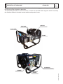
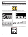
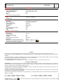
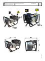
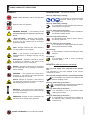
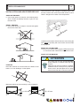
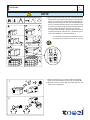
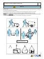
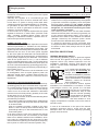
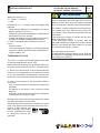
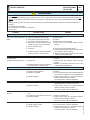
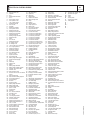
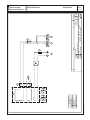
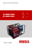
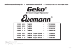
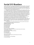
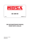
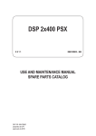
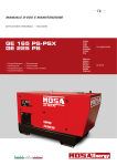
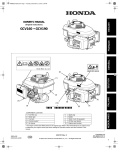
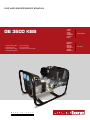
USE AND MAINTENANCE MANUAL GE 3500 KBS • Gruppo Elettrogeno • Stromerzeuger • Generating Set • Grupo Gerador • Groupe Electrogene • Генераторная Установка • Grupos Electrógenos M A D E I N I T A L Y Codice Code Code Codigo Kodezahl Código Код 253759003 Edizione Edition Édition Edición Ausgabe Edição Издание 02.2014 DESCRIPTION OF THE MACHINE GE 3500 KBS M 0 REV.0-02/14 The generating set is a unit which transforms the mechanical energy, generated by endothermic engine, into electric energy, through an alternator. The assembling is made on a steel structure, on which are provided elastic supports which must damp the vibrations and also eliminate sounds which would produce noise. MUFFLER FUEL TANK FRONT PANEL FRAME ALTERNATOR VIBRATION DAMPER 06/02/14 25375-GB ENGINE INDEX GE 3500 KBS M 1 REV.0-02/14 QUALITY SYSTEM COPYRIGHT NOTES CE MARK DECLARATION OF CONFORMITY TECHNICAL DATA SYMBOLS AND SAFETY PRECAUTIONS INSTALLATION AND ADVICE BEFORE USE INSTALLATION AND ADVICE INSTALLATION AND DIMENSIONS UNPACKING TRANSPORT AND DISPLACEMENTS SET-UP FOR OPERATION STARTING AND STOPPING THE ENGINE LEGEND / CONTROLS USE AS A GENERATOR TROUBLE SHOOTING MAINTENANCE STORAGE CUST OFF ELECTRICAL SYSTEM 06/02/14 25375-GB M 01 M 1.01 M 1.1 M 1.4 M 1.4.1 M 1.5 M 2 - 2.1 M 2.5 -…. M 2.6 M 2.7 M3 M 4.1 M 25 M 26 M 31 M 37 -….. M 40.2 M 43 M 45 M 46 M 61-….. M 1.01 Copyright REV.0-10/02 ! ATTENTION This use and maintenance manual is an important part of the machines in question. The assistance and maintenance personel must keep said manual at disposal, as well as that for the engine and alternator (if the machine is synchronous) and all other documentation about the machine. We advise you to pay attention to the pages concerning the security (see page M1.1). All rights are reserved to said Company. It is a property logo of MOSA division of B.C.S. S.p.A. All other possible logos contained in the documentation are registered by the respective owners. + The reproduction and total or partial use, in any form and/or with any means, of the documentation is allowed to nobody without a written permission by MOSA division of B.C.S. S.p.A. To this aim is reminded the protection of the author’s right and the rights connected to the creation and design for communication, as provided by the laws in force in the matter. In no case MOSA division of B.C.S. S.p.A. will be held responsible for any damaga, direct or indirect, in relation with the use of the given information. 10/10/02 M1-01-GB MOSA division of B.C.S. S.p.A. does not take any responsibility about the shown information on firms or individuals, but keeps the right to refuse services or information publication which it judges discutible, unright or illegal. Notes M 1-1 REV.1-03/14 INFORMATION Dear Customer, We wish to thank you for having bought a high quality set. Our sections for Technical Service and Spare Parts will work at best to help you if it were necessary. To this purpose we advise you, for all control and overhaul operations, to turn to the nearest authorized Service Centre, where you will obtain a prompt and specialized intervention. + In case you do not profit on these Services and some arts are replaced, please ask and be sure that are used exclusively original parts; this to guarantee that the performances and the initial safety prescribed by the norms in force are re-established. INFORMATION OF GENERAL TYPE In the envelope given together with the machine and/or set you will find: the manual for Use Maintenance and Spare Parts, the manual for use of the engine and the tools (if included in the equipment), the guarantee (in the countries where it is prescribed by law). The Manufacturer shall not be liable for ANY USE OF THE PRODUCT OTHER THAN THAT PRECISELY SPECIFIED IN THIS MANUAL and is thus not liable for any risks which may occur as a result of IMPROPER USE. The Company does not assume any liability for any damage to persons, animals or property. Our products are made in conformity with the safety norms in force, for which it is advisable to use all these devices or information so that the use does not bring damage to persons or things. +The use of non original spare parts will cancel immediately any guarantee and Technical Service obligation. While working it is advisable to keep to the personal safety norms in force in the countries to which the product is destined (clothing, work tools, etc.). NOTES ABOUT THE MANUAL Before actioning the machine please read this manual attentively. Follow the instructions contained in it, in this way you will avoid inconveniences due to negligence, mistakes or incorrect maintenance. The manual is for qualified personnel, who knows the rules: about safety and health, installation and use of sets movable as well as fixed. Do not modify for any motive parts of the machine (fastenings, holes, electric or mechanical devices, others..) if not duly authorized in writing: the responsibility coming from any potential intervention will fall on the executioner as in fact he becomes maker of the machine. You must remember that, in case you have difficulties for use or installation or others, our Technical Service is always at your disposal for explanations or interventions. The manual for Use Maintenance and Spare Parts is an integrant part of the product. It must be kept with care during all the life of the product. In case the machine and/or the set should be yielded to another user, this manual must also given to him. Do not damage it, do not take parts away, do not tear pages and keep it in places protected from dampness and heat. + Notice: the manufacturer, who keeps the faculty, apart the essential characteristics of the model here described and illustrated, to bring betterments and modifications to parts and accessories, without putting this manual uptodate immediately. 10/10/02 M1-1 GB_REV.1 You must take into account that some figures contained in it want only to identify the described parts and therefore might not correspond to the machine in your possession. M 1.4 CE MARK REV.7-02/14 Any of our product is labelled with CE marking attesting its conformity to appliable directives and also the fulfillment of safety requirements of the product itself; the list of these directives is part of the declaration of conformity included in any machine standard equipment. Here below the adopted symbol: CE marking is clearly readable and unerasable and it can be either part of the data-plate. TYPE SERIAL N° Made in UE-ITALY TYPE/N° VOLTAGE(V) POWER(W) Hz G P.F. I.CL. KVA V(V) I(A) LTP POWER IN ACCORDANCE WITH ISO 8528 n Pmax RPM TEMP. kW ALTIT. °C m IP Kg The indication is shown in a clear, readable and indeleble way on a sticker. 10/10/02 M1-4 GB Furthermore, on each model it is shown the noise level value; the symbol used is the following: GE 3500 KBS Technical data M 1.5 REV.0-02/14 Technical Data GE 3500 KBS *Stand-by single-phase power *PRP single-phase power Frequecy Cos ϕ * Output powers according to ISO 8528-1 ALTERNATOR 3.2 kVA (2.9 kW) / 230 V / 13.9 A 2.9 kVA (2.6 kW) / 230 V / 12.6 A 50 Hz 0.9 GENERATOR Self-excited, self-regulated, brushless Type Insulation class ENGINE synchronous, single-phase H Mark / Model Type / Cooling system Cylinder / Displacement *Stand-by power *PRP power Speed Fuel consumption (75% of PRP) Engine oil capacity Starter * Powers according to SAE J1349 GENERAL SPECIFICATION KOHLER CH 270 Command PRO Gasoline 4-Stroke OHV / Air 1 / 208 cm3 4 kW (5.4 HP) 3.6 kW (4.9 HP) 3000 rpm 1.2 l/h 0.6 l recoil Battery charge Fuel tank capacity Running time (75% of PRP) Protection Dimensions max. on base Lxwxh * Weight (dry) * Measured acoustic power LwA (pressure LpA) Guaranteed acoustic power LwA (pressure LpA) * Dimensions and weight without trolley/trailer. 12 V - 10A 4.0 l 3.3 h IP 23 580x420x420 37 Kg 96 dB(A) (71 dB(A) @ 7 m) 96 dB(A) (71 dB(A) @ 7 m) 2000 / 14 / CE OUTPUT Declared power according to ISO 8528-1 (temperature 25°C, 30% relative humidity, altitude 100 m above sea level). (*Stand-by) = maximum available power for use at variable loads for a yearly number of hours limited at 500 h. No overload is admitted. (**Prime power PRP) = maximum available power for use at variable loads for a yearly illimited number of hours. The average power to be taken during a period of 24 h must not be over 80% of the PRP. It’s admitted overload of 10% each hour every 12 h. In an approximative way one reduces: of 1% every 100 m altitude and of 2.5% for every 5°C above 25°C. Lp a 1 meter = 95 dB(A) - 8 dB(A) = 87 dB(A) Lp a 4 meters = 95 dB(A) - 20 dB(A) = 75 dB(A) PLEASE NOTE: the symbol according to 2000/14/CE directive. 2000 / 14 / CE Lp a 7 meters = 95 dB(A) - 25 dB(A) = 70 dB(A) Lp a 10 meters = 95 dB(A) - 28 dB(A) = 67 dB(A) 06/02/14 25375-GB ACOUSTIC POWER LEVEL ATTENTION: The concrete risk due to the machine depends on the conditions in which it is used. Therefore, it is up to the enduser and under his direct responsibility to make a correct evaluation of the same risk and to adopt specific precautions (for instance, adopting a I.P.D. -Individual Protection Device) Acoustic Noise Level (LWA) - Measure Unit dB(A): it stands for acoustic noise released in a certain delay of time. This is not submitted to the distance of measurement. Acoustic Pressure (Lp) - Measure Unit dB(A): it measures the pressure originated by sound waves emission. Its value changes in proportion to the distance of measurement. The here below table shows examples of acoustic pressure (Lp) at different distances from a machine with Acoustic Noise Level (LWA) of 95 dB(A) when with acoustic noise values, indicates that the device respects noise emission limits GE 3500 KBS M 2.7 REV.0-02/14 06/02/14 25375-I Installazione e dimensioni D Luftzirkulation und abmessungen Installation and dimensions E Instalación y dimensiones Installation et dimensions NL M 2 WARNINGS REV.1-02/14 The installation and general warnings regarding operations are aimed achieving correct use of the machine and/or apparatus in the place where it is used as a genset and/or motor welder. - Advice to the User about the safety: + NB: The information contained in the manual can be changed without notice. Any damage caused in connection with the use of these instructions shall not be considered as they are only indicative. Remember that the non observance of the indications reported by us might cause damage to persons or things. It is understood, that local dispositions and/or laws must be respected. ! DANGEROUS This heading warns of an immediate danger for persons as well for things. Not following the advice can result in serious injury or death. ! WARNING This heading warns of situations which could result in injury for persons or damage to things. ! CAUTION To this advice can appear a danger for persons as well as for things, for which can appear situations bringing material damage to things. ! IMPORTANT ! NOTE ! ATTENTION These headings refer to information which will assis you in the correct use of the machine and/or accessories. + FIRST AID. In case the operator shold be sprayed by accident, from corrosive liquids a/o hot toxic gas or whatever event which may cause serious injuries or death, predispose the first aid in accordance with the ruling labour accident standards or of local instructions. Skin contact Wash with water and soap Eyes contact Irrigate with plenty of water, if the irritation persists contact a specialist Ingestion Do not induce vomit as to avoid the intake of vomit into the lungs, send for a doctor Suction of liquids from If you suppose that vomit has entered the lungs (as in case of spontaneous vomit) take the subject to the lungs hospital with the utmost urgency Inhalation In case of exposure to high concentration of vapours take immediately to a non polluted zone the person involved + FIRE PREVENTION. In case the working zone,for whatsoever cause goes on fire with flames liable to cause severe wounds or death, follow the first aid as described by the ruling norms or local ones. Appropriated Carbonate anhydride (or carbon dioxyde) powder, foam, nebulized water Not to be used Avoid the use of water jets Other indications Cover eventual shedding not on fire with foam or sand, use water jets to cool off the surfaces close to the fire Particular protection Wear an autorespiratory mask when heavy smoke is present Useful warnings Avoid, by appropriate means to have oil sprays over metallic hot surfaces or over electric contacts (switches,plugs,etc.). In case of oil sprinkling from pressure circuits, keep in mind that the inflamability point is very low. 10/06/00 M2GB EXTINCTION MEANS M 2-1 SYMBOLS AND SAFETY PRECAUTIONS REV.2-06/10 STOP - Read absolutely and be duly attentive Read and pay due attention ! GENERAL ADVICE - If the advice is not respected damage can happen to persons or things. HIGH VOLTAGE - Attention High Voltage. There can be parts in voltage, dangerous to touch. The non observance of the advice implies life danger. FIRE - Danger of flame or fire. If the advice is not respected fires can happen. HEAT - Hot surfaces. If the advice is not respected burns or damage to things can be caused. EXPLOSION - Explosive material or danger of explosion. in general. If the advice is not respected there can be explosions. WATER - Danger of shortcircuit. If the advice is not respected fires or damage to persons can be caused. SMOKING - The cigarette can cause fire or explosion. If the advice is not respected fires or explosions can be caused. ACIDS - Danger of corrosion. If the advice is not respected the acids can cause corrosions with damage to persons or things. PROHIBITIONS No harm for persons Use only with safety clothing It is compulsory to use the personal protection means given in equipment. Use only with safety clothing It is compulsory to use the personal protection means given in equipment. Use only with safety protections It is a must to use protection means suitable for the different welding works. Use with only safety material It is prohibited to use water to quench fires on the electric machines. Use only with non inserted voltage It is prohibited to make interventions before having disinserted the voltage. No smoking It is prohibited to smoke while filling the tank with fuel. No welding It is forbidden to weld in rooms containing explosive gases. ADVICE No harm for persons and things Use only with safety tools, adapted to the specific use It is advisable to use tools adapted to the various maintenance works. Use only with safety protections, specifically suitable It is advisable to use protections suitable for the different welding works. Use only with safety protections It is advisable to use protections suitable for the different daily checking works. WRENCH - Use of the tools. If the advice is not respected damage can be caused to things and even to persons. Use only with safety protections It is advisable to use all protections while shifting the machine. PRESSION - Danger of burns caused by the expulsion of hot liquids under pressure. Use only with safety protections It is advisable to use protections suitable for the different daily checking works.and/or of maintenance. ACCES FORBIDDEN to non authorized peaple. 26/11/99 M2-1GB SYMBOLS M 2.6 INSTALLATION AND ADVICE REV.1-06/07 INSTALLATION AND ADVICE BEFORE USE GASOLINE ENGINES + Use in open space, air swept or vent exhaust gases, which contain the deathly carbone oxyde, far from the work area. Check that the air gets changed completely and the hot air sent out does not come back inside the set so as to cause a dangerous increase of the temperature. 1,5 m DIESEL ENGINES + Use in open space, air swept or vent exhaust gases far from the work area. 1,5 1,5 m m UT P UICTO AOR TC DISS SU GHAA EX + Make sure that the machine does not move during the work: block it possibly with tools and/or devices made to this purpose. MOVES OF THE MACHINE + At any move check that the engine is off, that there are no connections with cables which impede the moves. PLACE OF THE MACHINE ! POSITION Place the machine on a level surface at a distance of at least 1,5 m from buildings or other plants. ATTENTION For a safer use from the operator DO NOT fit the machine in locations with high risk of flood. Please do not use the machine in weather conditions which are beyond IP protection shown both in the data plate and on page named "technical data" in this same manual. Maximum leaning of the machine (in case of dislevel) 10° = 20° max 10° 10° = 20° max 26/11/99 M2-6GB 10° M 3 UNPACKING REV.1-02/04 NOTE ! + Be sure that the lifting devices are: correctly mounted, adequate for the weight of the machine with it’s packaging, and conforms to local rules and regulations. When receiving the goods make sure that the product has not suffered damage during the transport, that there has not been rough handling or taking away of parts contained inside the packing or in the set. In case you find damages, rough handling or absence of parts (envelopes, manuals, etc.), we advise you to inform immediately our Technical Service. For eliminating the packing materials, the User must keep to the norms in force in his country. 1 A B 1)Take the machine (C) out of the shipment packing. Take out of the envelope (A) the user’s manual (B). 2)Read: the user’s manual (B), the plates fixed on the machine, the data plate. C 30/03/00 M3GB 2 TRANSPORT AND DISPLACEMENTS COVERED UNITS M 4-1 REV.2-09/11 ! NOTE Transportation must always take place with the engine off, electrical cables and starting battery disconnected and fuel tank empty. Be sure that the lifting devices are: correctly mounted, adequate for the weight of the machine with it’s packaging, and conform to local rules and regulations. Only authorized persons involved in the transport of the machine should be in the area of movement. DO NOT LOAD OTHER PARTS WHICH CAN MODIFY WEIGHT AND BARICENTER POSITION. IT IS STRICTLY FORBIDDEN TO DRAG THE MACHINE MANUALLY OR TOW IT BY ANY VEHICLE (model with no CTM accessory). If you did not keep to the instructions, you could damage the structure of the machine. 15/01/01 M4GB Weight max. per person: 35 kg Total max. weight; 140 kg Set-up for operation GE 2500 SR FAMILY GE 3500 KBS LUBRICANT M 25 REV.0-11/10 AIR FILTER Please refer to the motor operating manual for the recommended viscosity. Check that the dry air filter is correctly installed and that there are no leaks around the filter which could lead to infiltrations of non-filtered air to the inside of the motor. RECOMMENDED OIL The manufacturer recommends selecting AGIP engine oil. Refer to the label on the motor for the recommended products. ! WARNING Do not use the machine if it is not in good technical condition The machine must be in good working order before being used. Defects, especially those which regard the safety of the machine, must be repaired before using the machine. Do not use without protective devices provided Removing or disabling protective devices on the machine is prohibited. Oil fill tap / dipstick EARTH TERMINAL Upper oil level MOTORS WITH OIL ALERT DEVICE The “Oil Alert” system is designed to prevent damage to the motor due to an insufficient quantity of oil in the cup. This system automatically shuts off the motor before the oil level falls below the safety limit. If the motor does not start up again after shutting itself off, check the oil level. FUEL ! ATTENTION Gasoline is highly flammable. Refuel with motor shut off in a flat surfaced well-ventilated area. Do not refuel in the presence of flames. Avoid spilling fuel. Any eventual spilled fuel and fumes are flammable. Clean any dispersions of fuel before starting up the motor. Fill the tank with gasoline for automobiles (preferably lead free or with low lead content in order to reduce deposits in the combustion chamber to a minimum). For further details on the type of gasoline to use, see the motor operating manual supplied. Do not fill the tank completely; leave a space of approx. 10 mm between the fuel level and the wall of the tank to allow for expansion. The group is not fitted with differential switch, therefore, the machine MUST NOT be intentionally connected to earth, attaching cables must be of 3 wires and the electrical equipment on which it being used must have an extension length limited to 100-200 metres. This limitation of circuit extension length is fundamental for safety. The cables must be SUITED to the environment in which they are to be used. Bear in mind that at temperatures below 5°C PVC cables become rigid and the PVC insulation tends to split at the first crease. Using double insulated equipment is advisable, this is identifiable by the symbol and for having no earth facility. In addition, supplying only one tool at a time, the protection against indirect contact is assured by “electrical separation”. If the machine is designed to supply circuits with more complex or located in potentially Electric particular is required to interpose between the plug and load a complete picture of distribution of all electrical protections required by regulations relating to electrical installations. For example: you can use a distribution system TN-S. In this case one of the phases, used as a neutral must be grounded, must be mounted within a differential switch (ID) bipolar 30mA, input jacks that are connected to appliances, terminal on the generating set to be used as earth connection, earthing of the installation where you go to work. WARNING: Connect the generator neutral to ground the first ID. 12/11/10 25370-GB To check the oil level: 1. Remove the oil-fill tap (24) and clean the dipstick (23). 2. Insert the dip-stick into the oil filler without screwing it in. 3. If the oil level is low, fill with recommended oil up to the top of the oil filler. Starting - Stopping GE 3500 KBS M 26 REV.0-02/14 ATTENTION: Check daily Allow the start-up knob to re-enter slowly, avoiding having it knock against the motor and thereby damaging the start-up system. NOTE ! Do not alter the primary conditions of regulation and do not touch the sealed parts. STARTING 1. Turn the fuel cock (87) to OPEN. (87) FUEL VALVE 2. Switch the choke control (66) to ON (66) CHOKE LEVER STOPPING THE ENGINE To stop the engine in an emergency, simply turn the engine switch to the OFF position. Under normal conditions, use the following procedure: 1) stop to draw single-phase current from the auxiliary sockets 2) Wait for a few minutes to allow the machine to cool off, take however into consideration the prescriptions given in the engine use manual 3) Turn the engine switch to the OFF position. (28) ENGINE SWITCH N.B.: Do not use the air valve if the motor is hot or the air temperature is too high. 4. Shut the gasoline cock. 3.Turn the engine switch (28) to the ON position (87) FUEL VALVE (28) ENGINE SWITCH Lightly pull the start-up knob (73) until meeting resistance, then pull decisively. (73) STARTER GRIP RUNNING-IN CAUTION During the first 50 hours of operation, do not use more than 60% of the maximum output power of the unit and check the oil level frequently, in any case please stick to the rules given in the engine use manual. 06/02/14 25375-GB ! Comandi Controls Commandes D E NL Bedienelemente M 31 GE 3500 KBS REV.0-02/14 26 73 66 87 O1 31 28 23 - 24 27 15 22 59B F Q4 12 12 15 22 23 24 26 27 28 31 59B 66 73 87 F O1 Q4 Descrizione Presa di messa a terra Presa di corrente in c.a. Filtro aria motore Asta livello olio motore Tappo caricamento olio motore Tappo serbatoio Silenziatore di scarico Comando stop Tappo scarico olio motore Protezione termica corrente aux Comando Choke Comando manuale avviamento Rubinetto carnurante Fusibile Spia luminosa press.olio/oil alert Prese carica batteria Description Earth terminal A.C. socket Engine air filter Oil level dipstick Engine oil reservoir cap Fuel tank cap Muffler Stop control Oil drain tap Aux current thermal switch Choke control Starting push button Fuel valve Fuse Oil press.warning light/Oil alert Battery charge sockets Description Prise de mise à terre Prises de courant en c.a. Filtre air moteur Jauge niveau huile moteur Bouchon remplissage huile moteur Bouchon réservoir Silencieux d’échappement Commande stop Bouchon décharge huile moteur Protection thermique courant aux. Commande Choke Commande manuelle démarrage Robinet de l’essence Fusible Voyant lumineux press.huile/oil alert Prises charge batterie Referenzliste Erdanschluss Steckdose AC Luftfilter Motor Ölmess-Stab Füllverschluss Motoröl Füllverschluss Kraftstofftank Auspufftopf Stop-Hebel Ablassöffnung Motoröl Thermoschutz Hilfsstrom Choke-Hebel Taste start Kraftstoffventil Sicherung Kontrolleuchte Oeldruck Steckdose Batterielader 06/02/14 25375-I Pos. M 37 Using the generator REV.3-11/11 ! WARNING It is absolutely forbidden to connect the unit to the public mains and/or another electrical power source . Access forbidden to area adjacent to electricity-generating group for all nonauthorized personnel. ! WARNING For the canopy generator sets provided with doors, the following instruction shall be observed. During the normal operation, the doors of the engine compartment and/or the electrical box shall be kept closed, locked up if possible, as they must be considered in all respects as protection barriers. The access to the internal parts shall occur for maintenance purposes only, by qualified personnel and, in any case, when the engine is stopped. The electricity-generating groups are to be considered electrical energy producing stations. The dangers of electrical energy must be considered together with those related to the presence of chemical substances (fuels, oils, etc.), rotating parts and waste products (fumes, discharge gases, heat, etc.). GENERATION IN AC (ALTERNATING CURRENT) Before each work session check the efficiency of the ground connection for the electricity-generating group if the distribution system adopted requires it, such as, for example, the TT and TN systems. Check that the electrical specifications for the units to be powered - voltage, power, frequency - are compatible with those of the generator. Values that are too high or too low for voltage and frequency can damage electrical equipment irreparably. In some cases, for the powering of three-phase loads, it is necessary to ensure that the cyclic direction of the phases corresponds to the installation’s requirements. Connect the electric devices to be powered to the AC sockets, using suitable plugs and cables in prime condition. Before starting up the group, make certain no dangerous situations exist on the installation to be powered. Check that the thermal-magnetic switch (Z2) is in the OFF position (input lever in downward position). Start up the electricity-generating group, positioning the thermal-magnetic switch (Z2) and differential switch (D) to ON (input lever in upward position). Before powering on the utilities, check that the voltmeter (N) and frequency meter (E2) indicate nominal values; in addition, check on the voltmeter change-over switch (H2) (where it is assembled) that the three line voltages are the same. + In the absence of a load, the values for voltage and frequency can be greater than their nominal values. See sections on VOLTAGE and FREQUENCY. OPERATING CONDITIONS POWER The electrical power expressed in kVA on an electricitygenerating group is the available output power to the reference environmental conditions and nominal values for: voltage, frequency, power factors (cos ϕ). There are various types of power: PRIME POWER (PRP), STAND-BY POWER established by ISO 8528-1 and 3046/1 Norms, and their definitions are listed in the manual’s TECHNICAL SPECIFICATIONS page. + During the use of the electricity-generating group NEVER EXCEED the power indications, paying careful attention when several loads are powered simultaneously. VOLTAGE GENERATORS WITH COMPOUND SETTING (THREEPHASE) GENERATORS WITH CONDENSER SETTING (SINGLEPHASE) In these types of generators, the no-load voltage is generally greater than 3–5% with respect to its nominal value; f.e. for nominal voltage, threephase 400Vac or singlephase 230Vac, the no-load voltage can be comprised between 410-420V (threephase) and 235245V (singlephase). The precision of the load voltage is maintained within ±5% with balanced loads and with a rotation speed variation of 4%. Particularly, with resistive loads (cos ϕ = 1), a voltage over-elevation occurs which, with the machine cold and at full load, can even attain +10 %, a value which in any case is halved after the first 10-15 minutes of operation. The insertion and release of the full load, under constant rotation speed, provokes a transitory voltage variation that is less than 10%; the voltage returns to its nominal value within 0.1 seconds. GENERATORS WITH ELECTRONIC SETTING (A.V.R.) In these types of generators, the voltage precision is maintained within ±1,5%, with speed variations comprised from -10% to +30%, and with balanced loads. The voltage is the same both with no-load and with load; the insertion and release of the full load provokes a transitory voltage variation that is less than 15%; the voltage returns to its nominal value within 0.2–0.3 seconds. FREQUENCY The frequency is a parameter that is directly dependent on the motor’s rotation speed. Depending on the type of alternator, 2 or 4 pole, we will have a frequency of 50/60 Hz with a rotation speed of 3000/3600 or 1500/1800 revolutions per minute. 12/06/03 M37GB_1500G_GE I GB F M 37.1 Using the generator The frequency, and therefore the number of motor revolutions, is maintained constant by the motor’s speed regulation system. Generally, this regulator is of a mechanical type and presents a droop from no-load to nominal load which is less than 5 % (static or droop), while under static conditions precision is maintained within ±1%.Therefore, for generators at 50Hz the no-load frequency can be 52–52.5 Hz, while for generators at 60Hz the no-load frequency can be 62.5-63Hz. In some motors or for special requirements the speed regulator is electronic; in these cases, precision under static operating conditions attains ±0.25%, and the frequency is maintained constant in operation from noload to load (isochronal operation). POWER FACTOR - COS ϕ The power factor is a value which depends on the load’s electrical specifications; it indicates the ratio between the Active Power (kW) and Apparent Power (kVA). The apparent power is the total power necessary for the load, achieved from the sum of the active power supplied by the motor (after the alternator has transformed the mechanical power into electrical power), and the Reactive Power (kVAR) supplied by the alternator. The nominal value for the power factor is cos ϕ = 0,8; for different values comprised between 0.8 and 1 it is important during usage not to exceed the declared active power (kW), so as to not overload the electricity-generating group motor; the apparent power (kVA) will diminish proportionally to the increase of cos ϕ. For cos ϕ values of less than 0.8 the alternator must be downgraded, since at equal apparent power the alternator should supply a greater reactive power. For reduction coefficients, contact the Technical Service Department. START-UP OF ASYNCHRONOUS MOTORS The start-up of asynchronous motors from an electricitygenerating group can prove critical because of high startup currents the asynchronous motor requires (I start-up = up to 8 times the nominal current In.). The start-up current must not exceed the alternator’s admissible overload current for brief periods, generally in the order of 250–300% for 10–15 seconds. To avoid a group oversize, we recommend following these precautionary measures: - in the case of a start-up of several motors, subdivide the motors into groups and set up their start-up at intervals of 30–60 seconds. - when the operating machine coupled to the motor allows it, see to a start-up with reduced voltage, star point/triangle start-up or with autotransformer, or use a soft-start system. In all cases, when the user circuit requires the start-up of an asynchronous motor, it is necessary to check that there are no utilities inserted into the installation, which in the case of a voltage droop can cause more or less serious disservices (opening of contact points, temporary lack of power to control and command systems, etc.). REV.1-09/05 SINGLE-PHASE LOADS Power to monophase utilities by means of three-phase generators requires some operating limitations. - In single-phase operation, the declared voltage tolerance can no longer be maintained by the regulator (compound or electronic regulator), since the system becomes highly unbalanced. The voltage variation on the phases not affected by the power can prove dangerous; we recommend sectioning the other loads eventually connected. - The maximum power which can be drawn between Neutral and Phase (start connection) is generally 1/3 of the nominal three-phase power; some types of alternators even allow for 40%. Between two Phases (triangle connection) the maximum power cannot exceed 2/3 of the declared three-phase power. - In electricity-generating groups equipped with monophase sockets, use these sockets for connecting the loads. In other cases, always use the "R" phase and Neutral. ELECTRIC PROTECTIONS THERMAL-MAGNETIC SWITCH The electricity-generating group is protected against short-circuits and against overloads by a thermalmagnetic switch (Z2) situated upstream from the installation. Operating currents, both thermic and magnetic, can be fixed or adjustable in relation to the switch model. + In models with adjustable operating current do not modify the settings, since doing so can compromise the installation’s protection or the electricity-generating group’s output characteristics. For eventual variations, contact our Technical Service Department. The intervention of the protection feature against overloads is not instantaneous, but follows a current overload/time outline; the greater the overload the less the intervention. Furthermore, keep in mind that the nominal operating current refers to an operating temperature of 30°C, so that each variation of 10°C roughly corresponds to a variation of 5% on the value of nominal current. In case of an intervention on the part of the thermal magnetic protection device, check that the total absorption does not exceed the electricity-generating group’s nominal current. 12/06/03 M37GB_1500G_GE I GB F I GB F M 37.2 Using the generator REV.1-09/05 DIFFERENTIAL SWITCH The differential switch or differential relay guarantee protection against indirect contacts due to malfunction currents towards the ground. When the device detects a malfunction current that is higher than the nominal current RESET or the set current, it intervenes by cutting off power to the circuit connected. In the case of an intervention A 1a0 M tx10 1 b 0 tx1 I° x1 x10 1c0 1d0 x0.1I° T5.10 T5.9 T5.3 RESET T5.5 A tx10 1 T5.2 T5.4 M tx1 I° x1 x10 RESET x0.1I° 1.5 0.5 0.25 TEST 0.2 2 0.3 0.1 2.5 0.4 ON TRIP 0.02 I° (A) T5.1 0.5 t (s) T5.6 T5.7 T5.8 by the differential switch, check that there are no sheathing defects in the installation: connection cables, sockets and plugs, utilities connected. + Before each work session, check the operation of the differential protection device by pressing the test key. The electricity-generating group must be in operation, and the lever on the differential switch must be in the ON position. THERMIC PROTECTION Generally present to protect against overloads on an individual power socket c.a. When the nominal operating current has been exceeded, the protection device intervenes by cutting off power to the socket. The intervention of the protection device against overloads is not instantaneous, but follows a current overload/time outline; the greater the overload the less the intervention. In case of an intervention, check that the current absorbed by the load does not exceed the protection’s nominal operating current. Allow the protection to cool off for a few minutes before resetting by pressing the central pole. ON OFF ! USAGE WITH EAS AUTOMATIC START-UP PANEL The electricity-generating group in combination with the EAS automatic start-up panel forms a unit for distributing electrical energy within a few seconds of a power failure from the commercial electrical power line. Below is some general operating information; refer to the automatic panel’s specific manual for details on installation, command, control and signalling operations. Perform connections on the installation in safety conditions. Position the automatic panel in RESET or LOCKED mode. Carry out the first start-up in MANUAL mode. Check that the generator’s LOCAL START / REMOTE START switch (I6) is in the REMOTE position. Check that the generator switches are enabled (input lever in upward position). Position the EAS panel in manual mode by pressing MAN. key, and only after having checked that there are no dangerous situations, press the START key to start the electricity-generating group. During the operation of the generator, all controls and signals from both the automatic panel and group are enabled; it is therefore possible to control its operation from both positions. In case of an alarm with a shutdown of the motor (low pressure, high temperature, etc.), the automatic panel will indicate the malfunction that has caused the stoppage, while the generator’s front panel will be disabled and will no longer supply any information. PRESS TO RESET ATTENTION 12/06/03 M37GB_1500G_GE Do not keep the central pole on the thermic protection forcefully pressed to prevent its intervention. USE AS A GENERATING SET GENERATION IN C.C. (Continuous Current) Maximum power in c.c.: P = 120W - V= 12V AC I = 10A Generation in c.c. is mainly used to recharge lead batteries. - Verify that the battery to be charged is not a dry battery, and that it is 12V c.c. - Position the generator and battery on a flat surface and distant from one another. - Connect the battery recharge cables one at a time, avoiding accidental contacts between them. + Note: use cables with a minimum section of 6 mm2. - Start the motor. - Once recharging is complete, proceed in opposite sequence, switching off the motor and disconnecting the cables, etc. THERMOPROTECTION GE 3200 SX - GE 350 KBS GE 4500 HBS / GE 4500 HBS-AVR GE 4500 SX / SXE-EAS / SXE-AVR EAS ! M 37.3 REV.0-12/11 ATTENTION The batteries produce explosive gas; sparks, flames, cigarettes, are to be kept far from them. Make sure that when they are being recharged there is adequate ventilation around the battery. The battery contains sulphuric acid (electrolyte). The contact with eyes and skin may cause severe lesions. Wear protective garments and eye protections. If the electrolyte comes in contact with the skin, wash with plenty of water. If the electrolyte comes in contact with the skin,wash with plenty of water.If it comes in contact with the eyes wash with fluent water for at least 15 minutes and rush for a doctor. The electrolyte is poisonous. If swallowed drink plenty of water or milk, then milk of magnesia or vegetable oil and call for a doctor. Keep away from children. The 12V c.c. output is protected against overloads by the thermoprotection device (59). When current is exceeded, the protection feature intervenes to cut off tension to the c.c. terminals (Q4). + Notes: the intervention of the thermoprotection feature is not instantaneous, but reacts according to an overcurrent/time characteristic, whereby the greater the overcurrent the quicker the intervention. In case of intervention by the protection feature, verify that: - the c.c. terminal /battery connections respect the polarities; - the battery is not faulty or has a short-circuited element; - the battery level is not too low, with the consequent recharge current being too high. 15/12/11 35470-GB Eliminate the cause and wait a few minutes to allow the thermoprotection to cool down. Reset the protection feature by pressing the central pole. If the protection should intervene once more, replace it with another one with matching intervention current specifications and/ PUSH TO RESET or contact the Service Department. TROUBLE-SHOOTING GE 2500 SR FAMILY GE 3500 KBS ! M 40.2 REV.0-11/10 WARNING ● Have qualified personnel do maintenance and troubleshooting work. ● Stop the engine before doing any work inside the machine. If for any reason the machine must be operated while working inside, pay attention moving parts, hot parts (exhaust manifold and muffler, etc.) electrical parts which may be unprotected when the machine is open. ● Remove guards only when necessary to perform maintenance, and replace them when the maintenance requiring their removal is complete. ● Use suitable tools and clothes ● Do not modify the components if not authorized. - See pag. M1.1 - Problem Possible cause ENGINE The motor does not start up, or 1) Engine switch OFF starts up and then stops imme- 2) Lack of or insufficient oil in the motor diately 3) Faulty motor stopping device (oil-alert) 4) Lack of fuel in tank or fuel tap closed 5) Bad gasoline. Gasoline oxidizes and deteriorates over time, causing hard starting 6) Dirty or faulty spark plug 7) Cold motor Solution 1) Turn engine switch to ON position 2) Refill or top off 3) Replace 4) Refill the tank. Open the fuel tap 5) Drain fuel tank and carburetor. Refuel with fresh gasoline. 6) Clean or check and eventually replace 7) Please keep the CHOKE control in “CLOSE” position 8) Fuel filter restricted, carburetor malfunction, for a longer time after the starting. ignition malfunction, valves stuck, etc. 8) Replace or repair faulty components. Ask for intervention of Service Department The motor does not accelerate. 1) Check the air filter Inconstant speed. Too little power provided by motor. 2) Bad gasoline Absence of output voltage 1) Clean or replace filter element(s). Refer to engine manual 2) Drain fuel tank and carburetor. Refuel with fresh gasoline 3) Replace or repair faulty components. Ask for inter3) Fuel filter restricted, carburetor malfunction, vention of Service Department ignition malfunction, valves stuck, etc. GENERATOR 1) Check the load connected and diminish 1) Protection tripped due to overload 2) Replace 2) Protection devices defective 3) Carry out external spark test as indicated in alternator 3) Alternator not sparked manual. Ask for intervention of Service Department 4) Check winding, diodes, etc. on alternator (Refer to 4) Alternator defective alternator manual). Repair or replace. Ask for intervention of Service Department No-load voltage too low or too high 1) Incorrect motor running speed 2) Alternator defective 1) Check position of accelerator lever. Regulate speed to its nominal no-load value 2) Check winding, diodes, etc. on alternator (Refer to alternator manual). Repair or replace. Ask for intervention of Service Department Corrected no-load voltage too low 1) Incorrect motor running speed due to over- 1) Check the load connected and diminish with load load 2) Load with cos ϕ less than the nominal one. 2) Reduce or rephase load 3) Alternator defective 3) Check winding, diodes, etc. on alternator (Refer to alternator manual). Repair or replace. Ask for intervention of Service Department 1) Contacts malfunctioning 2) Irregular rotation of motor 3) Alternator defective 1) Check electrical connections and tighten 2) Ask for intervention of Service Department 3) Check winding, diodes, etc. on alternator (Refer to alternator manual). Repair or replace. Ask for intervention of Service Department 12/11/10 25370-GB Unstable tension M 43 MAINTENANCE REV.1-01/13 ! MOVING PARTS can injure WARNING ●● Have qualified personnel do maintenance and troubleshooting work. ●● Stop the engine before doing any work inside the machine. If for any reason the machine must be operated while working inside, pay attention moving parts, hot parts (exhaust manifold and muffler, etc.) electrical parts which may be unprotected when the machine is open. ●● Remove guards only when necessary to perform maintenance, and replace them when the maintenance requiring their removal is complete. ●● Please wear the appropriate clothing and make use of the PPE (Personal Protective Equipment), according to the type of intervention (protective gloves, insulated gloves, glasses). ●● Do not modify the components if not authorized. - See pag. M1.1 - NOTE By maintenance at care of the utilizer we intend all the operatios concerning the verification of mechanical parts, electrical parts and of the fluids subject to use or consumption during the normal operation of the machine. For what concerns the fluids we must consider as maintenance even the periodical change and or the refills eventually necessary. Maintenance operations also include machine cleaning operations when carried out on a periodic basis outside of the normal work cycle. The repairs cannot be considered among the maintenance activities, i.e. the replacement of parts subject to occasional damages and the replacement of electric and mechanic components consumed in normal use, by the Assistance Authorized Center as well as by manufacturer. The replacement of tires (for machines equipped with trolleys) must be considered as repair since it is not delivered as standard equipment any lifting system. The periodic maintenance should be performed according to the schedule shown in the engine manual. An optional hour counter (M) is available to simplify the determination of the working hours. ! IMPORTANT In the maintenance operations avoid that polluting substances, liquids, exhausted oils, etc. bring damage to people or things or can cause negative effects to surroindings, health or safety respecting completely the laws and/or dispositions in force in the place. ENGINE and ALTERNATOR PLEASE REFER TO THE SPECIFIC MANUALS PROVIDED. Every engine and alternator manufacturer has HOT surface can hurt you maintenance intervals and specific checks for each model: it is necessary to consult the specific engine or alternator USER AND MAINTENANCE manual. VENTILATION Make certain there are no obstructions (rags, leaves or other) in the air inlet and outlet openings on the machine, alternator and motor. ELECTRICAL PANELS Check condition of cables and connections daily. Clean periodically using a vacuum cleaner, DO NOT USE COMPRESSED AIR. DECALS AND LABELS All warning and decals should be checked once a year and replaced if missing or unreadable. STRENUOUS OPERATING CONDITIONS Under extreme operating conditions (frequent stops and starts, dusty environment, cold weather,extended periods of no load operation, fuel with over 0.5% sulphur content) do maintenance more frequently. BATTERY WITHOUT MAINTENANCE DO NOT OPEN THE BATTERY The battery is charged automatically from the battery charger circuit suppplied with the engine. Check the state of the battery from the colour of the warning light which is in the upper part. - Green colour: battery OK - Black colour: battery to be recharged - White colour: battery to be replaced ! NOTE THE ENGINE PROTECTION NOT WORK WHEN THE OIL IS OF LOW QUALITY BECAUSE NOT CHARGED REGULARLY AT INTERVALS AS PRESCRIBED IN THE OWNER’S ENGINE MANUAL. 05/09/05 M43GB I GB F I GB F M 45 STORAGE REV.0-06/07 In case the machine should not be used for more than 30 days, make sure that the room in which it is stored presents a suitable shelter from heat sources, weather changes or anything which can cause rust, corrosion or damages to the machine. + Have qualified personnel prepare the machine for storage. GASOLINE ENGINE Start the engine: lt will run until it stops due to the lack of fuel. Drain the oil from the engine sump and fill it with new oil (see page M25). Pour about 10 cc of oil into the spark plug hole and screw the spark plug, after having rotated the crankshaft several times. Rotate the crankshaft slowly until you feel a certain compression, then leave it. In case of necessity for first aid and of fire prevention, see page. M2.5. ! IMPORTANT In the storage operations avoid that polluting substances, liquids, exhausted oils, etc. bring damage to people or things or can cause negative effects to surroindings, health or safety respecting completely the laws and/or dispositions in force in the place. In case the battery, for the electric start, is assembled, disconnect it. Clean the covers and all the other parts of the machine carefully. Protect the machine with a plastic hood and store it in o dry place. DIESEL ENGINE For short periods of time it is advisable, about every 10 days, to make the machine work with load for 15-30 minutes, for a correct distribution of the lubricant, to recharge the battery and to prevent any possible bloking of the injection system. For long periods of inactivity, turn to the after soles service of the engine manufacturer. Clean the covers and all the other parts of the machine carefully. 04/06/07 M45GB Protect the machine with a plastic hood and store it in a dry place. I GB F + M 46 CUST OFF REV.0-06/07 Have qualified personnel disassemble the machine and dispose of the parts, including the oil, fuel, etc., in a correct manner when it is to be taken out of service. As cust off we intend all operations to be made, at utilizer’s care, at the end of the use of the machine. This comprises the dismantling of the machine, the subdivision of the several components for a further reutilization or for getting rid of them, the eventual packing and transportation of the eliminated parts up to their delivery to the store, or to the bureau encharged to the cust off or to the storage office, etc. In case of necessity for first aid and fire prevention, see page M2.5. ! IMPORTANT In the cust-off operations avoid that polluting substances, liquids, exhausted oils, etc. bring damage to people or things or can cause negative effects to surroindings, health or safety respecting completely the laws and/or dispositions in force in the place. The several operations concerning the cust off, involve the manipulation of fluids potentially dangerous such as: lubricating oil and battery electrolyte. The dismantling of metallic parts liable to cause injuries or wounds, must be made wearing heavy gloves and using suitable tools. The getting rid of the various components of the machine must be made accordingly to rules in force of law a/o local rules. Particular attention must be paid when getting rid of: lubricating oils, battery electrolyte, and inflamable liquids such as fuel, cooling liquid. The machine user is responsible for the observance of the norms concerning the environment conditions with regard to the elimination of the machine being cust off and of all its components. In case the machine should be cust off without any previous disassembly it is however compulsory to remove: - tank fuel - engine lubricating oil - cooling liquid from the engine - battery 04/06/07 M45GB NOTE: The manufacturer is involved with custing off the machine only for the second hand ones, when not reparable. This, of course, after authorization. M 60 ELECTRICAL SYSTEM LEGENDE REV.11-06/14 E3 : Open circuit voltage switch F3 : Stop push-button G3 : Ignition coil H3 : Spark plug I3 : Range switch L3 : Oil shut-down button M3 : Battery charge diode N3 : Relay O3 : Resistor P3 : Sparkler reactor Q3 : Output power unit R3 : Electric siren S3 : E.P.4 engine protection T3 : Engine control PCB U3 : R.P.M. electronic regulator V3 : PTO HI control PCB Z3 : PTO HI 20 l/min push-button W3 : PTO HI 30 l/min push-button X3 : PTO HI reset push-button Y3 : PTO HI 20 l/min indicator A4 : PTO HI 30 l/min indicator B4 : PTO HI reset indicator C4 : PTO HI 20 l/min solenoid valve D4 : PTO HI 30 l/ min solenoid valve E4 : Hydraulic oil pressure switch F4 : Hycraulic oil level gauge G4 : Preheating glow plugs H4 : Preheating gearbox I4 : Preheating indicator L4 : R.C. filter M4 : Heater with thermostat N4 : Choke solenoid O4 : Step relay P4 : Circuit breaker Q4 : Battery charge sockets R4 : Sensor, cooling liquid temperature S4 : Sensor, air filter clogging T4 : Warning light, air filter clogging U4 : Polarity inverter remote control V4 : Polarity inverter switch Z4 : Transformer 230/48V W4 : Diode bridge, polarity change X4 : Base current diode bridge Y4 : PCB control unit, polarity inverter A5 : Base current switch B5 : Auxiliary push-button ON/OFF C5 : Accelerator electronic control D5 : Actuator E5 : Pick-up F5 : Warning light, high temperature G5 : Commutator auxiliary power H5 : 24V diode bridge I5 : Y/s commutator L5 : Emergency stop button M5 : Engine protection EP5 N5 : Pre-heat push-button O5 : Accelerator solenoid PCB P5 : Oil pressure switch Q5 : Water temperature switch R5 : Water heater S5 : Engine connector 24 poles T5 : Electronic GFI relais U5 : Release coil, circuit breaker V5 : Oil pressure indicator Z5 : Water temperature indicator W5 : Battery voltmeter X5 : Contactor, polarity change Y5 : Commutator/switch, series/parallel A6 : Commutator/switch B6 : Key switch, on/off C6 : QEA control unit D6 : Connector, PAC E6 : Frequency rpm regulator F6 : Arc-Force selector G6 : Device starting motor H6 : Fuel electro pump 12V c.c. I6 : Start Local/Remote selector L6 : Choke button M6 : Switch CC/CV N6 : Connector – wire feeder O6 : 420V/110V 3-phase transformer P6 : Switch IDLE/RUN Q6 : Hz/V/A analogic instrument R6 : EMC filter S6 : Wire feeder supply switch T6 : Wire feeder socket U6 : DSP chopper PCB V6 : Power chopper supply PCB Z6 : Switch and leds PCB W6 : Hall sensor X6 : Water heather indicator Y6 : Battery charge indicator A7 : Transfer pump selector AUT-0-MAN B7 : Fuel transfer pump C7 : "GECO" generating set test D7 : Flooting with level switches E7 : Voltmeter regulator F7 : WELD/AUX switch G7 : Reactor, 3-phase H7 : Switch disconnector I7 : Solenoid stop timer L7 : "VODIA" connector M7 : "F" EDC4 connector N7 : OFF-ON-DIAGN. selector O7 : DIAGNOSTIC push-button P7 : DIAGNOSTIC indicator Q7 : Welding selector mode R7 : VRD load S7 : 230V 1-phase plug T7 : V/Hz analogic instrument U7 : Engine protection EP6 V7 : G.F.I. relay supply switch Z7 : Radio remote control receiver W7 : Radio remote control trasnsmitter X7 : Isometer test push-button Y7 : Remote start socket A8 :Transfer fuel pump control B8 :Ammeter selector switch C8 :400V/230V/115V commutator D8 :50/60 Hz switch E8 :Cold start advance with temp. switch F8 :START/STOP switch G8 :Polarity inverter two way switch H8 :Engine protection EP7 I8 :AUTOIDLE switch L8 :AUTOIDLE PCB M8 :A4E2 ECM engine PCB N8 :Remote emergency stop connector O8 :V/A digital instruments and led VRD PCB P8 :Water in fuel Q8 :Battery disconnect switch R8 :Inverter S8 :Overload led T8 :Main IT/TN selector U8 :NATO socket 12V V8 :Diesel pressure switch Z8 :Remote control PCB W8 :Pressure turbo protection X8 :Water in fuel sender Y8 :EDC7-UC31 engine PCB A9 :Low water level sender B9 :Interface card C9 :Limit switch D9 :Starter timing card E9 :Luquid pouring level float F9 :Under voltage coil G9 : Low water level warning light H9 :Chopper driver PCB I9 :Fuel filter heater L9 :Air heater M9 :ON/OFF switch lamp N9 O9 P9 Q9 R9 S9 T9 U9 V9 Z9 W9 X9 Y9 : UP/DOWN button mast : Hydraulic unit solenoid valve : Hydraulic unit engine : Ignitor : Lamp : Power system : 48Vdc power system : LED projector : : : : : 26/07/04 M60GB A : Alternator B : Wire connection unit C : Capacitor D : G.F.I. E : Welding PCB transformer F : Fuse G : 400V 3-phase socket H : 230V 1phase socket I : 110V 1-phase socket L : Socket warning light M : Hour-counter N : Voltmeter P : Welding arc regulator Q : 230V 3-phase socket R : Welding control PCB S : Welding current ammeter T : Welding current regulator U : Current transformer V : Welding voltage voltmeter Z : Welding sockets X : Shunt W : D.C. inductor Y : Welding diode bridge A1 : Arc striking resistor B1 : Arc striking circuit C1 : 110V D.C./48V D.C. diode bridge D1 : E.P.1 engine protection E1 : Engine stop solenoid F1 : Acceleration solenoid G1 : Fuel level transmitter H1 : Oil or water thermostat I1 : 48V D.C. socket L1 : Oil pressure switch M1 : Fuel warning light N1 : Battery charge warning light O1 : Oil pressure warning light P1 : Fuse Q1 : Starter key R1 : Starter motor S1 : Battery T1 : Battery charge alternator U1 : Battery charge voltage regulator V1 : Solenoid valve control PCBT Z1 : Solenoid valve W1 : Remote control switch X1 : Remote control and/or wire feeder socket Y1 : Remote control plug A2 : Remote control welding regulator B2 : E.P.2 engine protection C2 : Fuel level gauge D2 : Ammeter E2 : Frequency meter F2 : Battery charge trasformer G2 : Battery charge PCB H2 : Voltage selector switch I2 : 48V a.c. socket L2 : Thermal relay M2 : Contactor N2 : G.F.I. and circuit breaker O2 : 42V EEC socket P2 : G.F.I. resistor Q2 : T.E.P. engine protection R2 : Solenoid control PCBT S2 : Oil level transmitter T2 : Engine stop push-button T.C.1 U2 : Engine start push-buttonT.C.1 V2 : 24V c.a. socket Z2 : Thermal magnetic circuit breaker W2 : S.C.R. protection unit X2 : Remote control socket Y2 : Remote control plug A3 : Insulation moitoring B3 : E.A.S. connector C3 : E.A.S. PCB D3 : Booster socket B R Alla Pag. To Page Da Pag. From Page - B + F H 230V/16A BL B GE 3500 KBS Macchina: Machine: Aux. (230Mx2/12Vdc) T Modifica Modification Denominazione: Denomination: Q4 R 10A F Balducci F. H 230V/16A BL B Disegnatore: Designer: 12A P4 10.02.2014 Data: Date: Dis. n°: Dwg. n°: 25375.prg Data Da t e Progetto: Project: 2 Approvato: Approved: 2 Dis. Appr. Desi. Ap p r . Pag.n° di n° Page n° of n° GE 3500 KBS 06/02/14 25375-I Esp. - + B B Stromlaufplan Esquema eléctrico LEGENDA COLORI KEY COLOR R ROSSO/RED B NERO/BLACK BL BLU/BLUE Y GIALLO/YELLOW Y Y C Y B B Y B BL B B B D E NL ROTOR A Schema elettrico Electric diagram Schemas electriques M 61.1 REV.0-02/14 MOSA div. della BCS S.p.A. Viale Europa, 59 20090 Cusago (Milano) Italy Tel.+39 - 0290352.1 Fax +39 - 0290390466 www.mosa.it