1
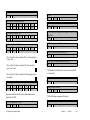
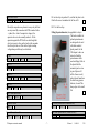
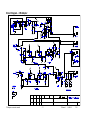
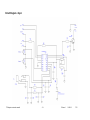
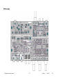
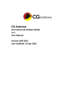
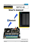
The Radio-Kits
CW Adapter
Construction and user manual
Author - Steve Drury G6ALU
List of contents
Section
Page no.
1. Specifications
2
2. Introduction
2
3. Choices
3
4. Construction
4
5. General construction practice
4
6. Component placement
5
7. Wiring up
8
8. Testing and adjustment
8
9. Boxing up
9
10. Operating instructions
10
11. In use
11
12. Plug and socket fitting instructions
12
13. Component Identification
12
14. Fault finding
14
15. Voltage table
15
16. Block diagram and circuit description
16
17. Circuit diagram – CW adapter
17
18. Circuit diagram - Keyer
18
19. PCB Pattern
19
20. PCB overlay
20
21. Change log
21
CW adapter construction manual
-1-
Released
14-04-09
V2.0
Introduction
Features
•
•
•
•
•
•
•
•
For some time MKARS80 owners have asked for a CW modification;
this unit has been provided to add CW functionality to any SSB
transceiver that has sufficient stability and a clean transmit spectrum.
To avoid “polluting” the CW spectrum with unwanted signals the
transmitter should have a well suppressed carrier and a linear audio
stage; when used with a correctly adjusted MKARS80 unwanted
spurious signals are > 40dB below the wanted carrier. In most
instances these artifacts will be masked by band noise.
Adds a CW function to simple SSB transceivers
Useful for CW sending practice
Shaped keying
Built in side tone (Approx. 800Hz)
Adjustable side-tone level, hang time and drive level
Switchable narrow receive filter
Reverse polarity protection (fuse protected)
Iambic memory keyer – by permission from DL4YHF
The PCB carries an Iambic keyer with memory function, the circuit
and microcontroller code were designed by Wolfgang DL4YHF and
are reproduced here with his permission. His web site
http://www.qsl.net/dl4yhf/pic_key.html carries full information.
Typical Specifications (13.8V supply)
Tone frequency
Audio output
Supply voltage
Loudspeaker
-
Approximately 800Hz
Approximately 0.5W
10-16V
8 Ohm (will work into 4 Ohm)
What started off as being a simple sine wave oscillator became more
complex as extra functionality was added, although now quite
complex this module shouldn’t pose too many problems to
constructors with only a little experience. To avoid any build issues
the constructor is strongly advised to follow the documented build
sequence.
The CW adapter is designed to be fitted “in-line” with the SSB radio;
that is the power, speaker, key and microphone connections are made
to the radio with plugs fitted to leads integral with the adapter.
CW adapter construction manual
-2-
Released
14-04-09
V2.0
Choices
The PCB is intended to be packaged into a case external to the
MKARS80 transceiver; one possibility is to build it into a
loudspeaker cabinet.
No case is supplied so, to be as flexible as possible, the PCB can be
separated in to 3 parts:
1. Main section – this carries most of the circuitry and is appropriately
fitted into the case so the switches, controls and sockets protrude
through the front panel. If separated from the rear section, mounting
holes for 3 x 3mm screws are provided, and if the rear PCB isn’t
separated then there are 5 mounting holes although only 4 are
required. There are also 3 fixing nuts on the potentiometer shafts that
should be used.
2. Rear panel – this will normally be separated from the main section to
enable utilisation of a larger case; to separate the two sections simply
score the connecting lands with a sharp knife and snap them apart. In
final assembly the two sections will need to be electrically connected
by joining pads marked A to A, B to B etc. This section has two 3mm
fixing holes.
3. Keyer PCB – this is a stand alone PCB which is intended to be fitted
into a small housing of its own, this is a dense board with two fixings;
the speed potentiometer shaft and a single 3mm screw hole and both
should be used. The keyer PCB can be incorporated into a case with
the CW adapter; a connection is made between “Key out” on the
keyer PCB and “Internal keyer” on the main board. When this link is
made the straight key input will over ride the keyer function. For
ground continuity a connection also has to be made between Gnd on
the keyer and point “B” on the main PCB.
CW adapter construction manual
-3-
Released
14-04-09
V2.0
the component leads it will be noticed that the solder “wicks” up the
hole through to the top surface, this is normal.
Construction
These instructions have been targeted at those with some construction
experience and who can identify the different components. Where out
of the ordinary parts have been used a short description follows the
component value.
All components are mounted on the component side of the board. The
PCB silk-screen gives the component locations, in cases where this is
difficult to read please refer to the printed overlay that is larger than
actual size. Note that components are numbered from left to right then
top to bottom of the board excepting the keyer which has its own
number sequence beginning at “60”. If you have difficulty in locating
a component position place a straight edge across the overlay and look
along its length, in this way components will be easy to locate.
The PCB has been designed to accommodate the components supplied
so if it doesn’t easily fit ask yourself if it belongs there!
General construction practice
Leaded or lead-free cored solder may be used. The solder must be
designed for electronics – do not use plumbers solder or additional
flux, as the flux is very corrosive. I use 22SWG (0.7mm) multi-core
type solder that seems most suitable for this type of work. A double
sided plated through hole (PTH) PCB has been used, this has the
advantage of greater stability and makes dry joints very unlikely;
however incorrectly fitted components can be very difficult to remove
so it’s important to fit them in the right place first time! If a
component is inadvertently fitted incorrectly it is easiest to cut off its
leads, apply the soldering iron and pull them out from the topside. A
small solder sucker or de-solder braid can be used to clear the holes
out ready for a replacement component to be fitted. When soldering
CW adapter construction manual
-4-
For a start, place just a few components in place before soldering
them, as experience grows you may find it more productive to fit a
larger number at a time. As each component is fitted put a mark in the
box provided, it’s very easy to forget the last component fitted
especially if you are distracted. If you make use of the component
overlay you will find it helpful if components are highlighted as they
are fitted. Components should be taken from one bag at a time
keeping the other sealed.
Everyone has their preferred method of retaining components prior to
soldering; I pull the leads through with long nose pliers and put a bend
in the component lead to stop it falling out of the board. A good policy
is not to crop leads until they have been soldered, this should stop you
from missing any soldered joints. As this is a PTH (plated through
hole) board, leads can be cropped quite close to the PCB without
damaging the soldered joint. A suitable solvent (isopropyl alcohol or
proprietary chemical) may be used to clean the flux from PCB after
assembly.
Where possible fit the
components so their values
are easily readable. Some
components MUST be
fitted in the correct
orientation as they are
polarised; this will be
indicated in the text.
The
components
are packed in
Released
14-04-09
V2.0
two bags, each bag contains a list of contents which will
show any substitutions that have been made.
22K (Red, red, orange, gold)
R9
R18
R30
Component placement
R42
R61
47k (Yellow, violet, orange, gold)
R12
R14
R23
R43
R24
R44
270k (Red, violet, yellow, gold)
R1
Resistors are quite small and are identified by four or five
colour bands; if in doubt use a multi-meter to confirm their
value.
33k (Orange, orange, orange, gold)
R36
Fit the following components from bag 1.
Be careful not to mix the 4K7 and 47K resistors, these two
values are often confused.
100K (Brown, black, yellow, gold)
R19
R20
R21
R32
56R (Green, blue, black, gold)
R38
100R (Brown, black, brown, gold)
R26
R27
R41
R65
4k7 (Yellow, violet, red, gold)
R16
R39 is “hidden” between the two push switches!
10K (Brown, black, orange, gold)
R2
R3
R11
R15
R39
R40
R34
R64
4R7 (Yellow, violet gold, gold)
R13
R17
82K (Grey, red, orange, gold)
R6
R8
R25
10R (Brown, black, black, gold)
R22
1K (Brown, black, red, gold)
R4
R5
R7
R31
R37
R35
R63
R66
CW adapter construction manual
R29
10k preset (Marked 103)
R33
R10
R60
Diodes are polarised devices so can only be fitted one way
round, match the band on one end of the encapsulation
with the bar printed on the PCB.
R28
R62
-5-
Released
14-04-09
V2.0
1N5401 diode (Large black package)
D1
1N4148 diode (Small glass package )
D2
D3
D4
D5
D7
D8
D9
D10
100nF ceramic (Marked 104)
C1
C2
C9
C66
1nF Ceramic (Marked 102)
C60
C62
C63
C67
C68
C11
C64
BC547B
TR2
TR3
D6
D11
BC557B
TR4
TR5
C23
78L08 (Looks like a transistor and is marked 78L08 in very
small letters)
IC1
LM324 Fit into previously fitted socket
IC2
C65
LM358 Fit into previously fitted socket
IC3
Fit an 8 pin IC socket in position IC3, note the notch goes
to pin 1 end.
PIC16F628A Fit into previously fitted socket
IC60
Fit an 14 pin IC socket in position IC2, note the notch
goes to pin 1 end.
IC4 should not be fitted into a socket as it uses the PCB
as a heat sink.
Fit an 18 pin IC socket to position IC60 noting the correct
orientation.
22nF Poly (Marked 22n)
C3
C4
C5
C18
C19
C20
C6
C21
LM386N-1
IC4
C17
Double pole push switches
SW1
SW2
Transistors should be fitted so their outline matches that
printed on the PCB.
Fit the following components from bag 2.
220nF Polyester (Marked .22)
C61
BC337-40 (Marked BC33740)
TR1
Q60
CW adapter construction manual
-6-
Released
14-04-09
V2.0
Fit two fuse clips to position F1, note that they have to be
fitted in the correct orientation for the fuse to fit.
Vertical tact switch
SW 60
SW 61
Fit F1 to the fuse clips.
Electrolytic capacitors are polarised so may only be fitted
one way round. By convention the PCB is marked with a
+ symbol, the + lead of a capacitor is longest, the
capacitor sleeve is also normally marked -. Fit the
capacitors against the PCB with zero lead length but
don’t put excessive force on the leads as this can make
the electrolyte leak out. Parts with a higher working
voltage than specified may be substituted.
1uF 63V
C10
C15
Fitting the potentiometers (also applicable to keyer)
The knobs available for
splined potentiometers
are designed to be used
with thick moulded
plastic panels; for the
CW adapter to have an
attractive finish the
potentiometer shafts
need modifying. Refer to
the photo: hold the
unwanted part in a vice
(a pair of pliers will
suffice if care is used)
and cut about 5mm from
the shaft using a junior
hacksaw, clean off the
sharp edges with a small
file.
C16
10uF 25V
C22
220uF 16V
C7
C8
C14
47uF 16V
C12
C13
Mono 3.5mm jack socket
CON 1
CON 5
2.1mm DC socket
CON 2
10k Linear potentiometer (marked B10K)
VR 1
VR 3
Stereo 3.5mm jack socket
CON 3
CON 4
100k Linear potentiometer (Marked B100K)
VR60
CW adapter construction manual
CON 60
-7-
Released
14-04-09
V2.0
The MKARS80 will be powered via the CW adapter, this
will help to keep the leads tidy.
470k Linear potentiometer (marked B470K)
VR 2
Fit the supplied black and red power wires to the 2.1mm
DC plug, cut and strip the insulation to an appropriate
length. Note the red lead goes to the center contact. The
stripped ends solder to pads marked “Power to Txcvr”,
black to “-” and red to “+”.
Temporarily fit the red LED between positions “LED +”
and “LED-”, the long lead goes to “LED +”.
Fit the two black knobs to the push switches.
If the keyer is to be housed separate from the CW adapter
fit a 3.5mm mono Jack plug to one end of a suitable length
of screened lead, connect the other end; braid to “Gnd”
and center core to “Key out”. If housing the keyer with the
CW adapter “key out” is connected to “Internal keyer” on
the main PCB.
Wiring up
If the loudspeaker / DC input section has been separated
from the main board, interconnections will have to be
made. Simply connect points A to A, B to B and C to C
with some hook up wire.
Cut an appropriate length of screened lead to go from the
CW adapter PCB to the MKARS80 loudspeaker socket;
lead lengths will depend on how the CW adapter will be
boxed and positioned relative to the MKARS80. Do not
use an excessive lead length.
Measure between R65 and ground with a resistance meter
and confirm the resistance is greater than 1k Ohms.
Treat the battery with respect. Fire doesn’t result if the
terminals are short-circuited but excessive heat may cause
the case to rupture; normal soldering though won’t be
hazardous.
Separate the two cores of a length of twin screened cable
and fit a 3.5mm mono Jack plug to one end of one of the
cores, if in doubt see fitting instructions later in manual.
Strip the other end and fit to solder pads marked “Audio
from Txvr”, braid goes to “-” and center core goes to “+”.
Vertical lithium cell
BAT 60
Once the battery is fitted you can measure the voltage
across R65 which in standby should be less than 1mV.
Cut a piece of double screened cable to go from the
MKARS80 microphone socket to the CW adapter, fit a
stereo 3.5mm Jack plug to one end, fit the other end to the
CW adapter; plug tip goes to “Mic”, ring to “PTT” and
both braids go to “Screen”.
CW adapter construction manual
Testing and Adjustment
First carefully inspect the PCB for any solder splashes or
obvious errors, measure between supply (the fuse is a
-8-
Released
14-04-09
V2.0
handy place) and ground to make sure there is no short
circuit; a resistance reading of over 1k Ohms is expected.
Pressing the paddle to the left generates dots and pressing
to the right generates dashes.
Boxing up
Connect a Morse key and loudspeaker, apply power and
listen for any unusual sounds or signs of heat (smoke!); if
all is well press the key and adjust the side-tone level so
you can hear the tone. Adjust R33 (tone frequency) for the
loudest tone.
A drilling template is provided for both front and back
panels. Note that all vertical dimensions are referenced to
the underside of the PCBs.
All potentiometers should be fixed to the front / back
panels with nuts provided.
Remove power and connect the MKARS80; power,
microphone and loudspeaker connections need to be
made to the radio. Fit a dummy load to the antenna
socket.
If fitting an internal loudspeaker, wire to the pads “Internal
loudspeaker”.
PCB pads are provided for connecting an internal battery if
desired, the negative terminal is isolated when an external
power source is plugged in; note that there is no provision
to recharge internal batteries.
Apply power and push the CW / SSB switch in; when
you press the key down the transceiver should go to
transmit; adjust the drive control until the LED just
extinguishes – this is a suitable setting but may need
adjusting when changing frequency, power supply or
antenna.
Adjust the hang control to suit your CW sending speed.
Connect an antenna and set the filter switch out, tune the
MKARS80 to find a CW station and confirm the filter
functions correctly when the button is pushed in. The
filter is quite narrow so you may need to adjust the
tuning to properly hear CW.
Keyer Testing
Plug in a paddle to the keyer and plug the keyer into the
CW adapter. Set both switches out on the CW adapter.
CW adapter construction manual
-9-
Released
14-04-09
V2.0
Operating instructions
CW adapter front panel connections and controls –
from left to right
WARNING
Be careful when using headphones as volume is dependent on
strength of received signals and at the very least this could
“surprise” the operator when tuning through a local station!
Headphone socket – 3.5mm Stereo socket accepts mono
or stereo headphones; a diode clipper limits the output
level but care should be taken to avoid hearing damage if
“loud” headphones are used.
The headphone socket has a limited output so should be used for
headphones!
Microphone – 3.5mm Stereo socket for electret
microphone and PTT as used with the MKARS80.
PHOTO HERE!
Straight key – 3.5mm socket for straight key. If the keyer
is fitted internally removal of straight key will change over
to keyer operation.
Audio filter – Pressed in for narrow (approx. 200Hz)
bandwidth and out for full transceiver bandwidth.
CW / SSB switch – Out for SSB operation and in for CW.
With the switch left out, pressing the key will not actuate
the PTT (the radio won’t transmit) although the side-tone
still functions; in this mode it is possible to accurately
“net” in to the received station.
The CW adapter fits in-line with the power, loudspeaker,
key and power supply: connect microphone, straight key,
loudspeaker and power to the CW adapter. Plug the leads
integral to the CW adapter into the MKARS80 power,
loudspeaker and microphone sockets.
Drive control – Sets the audio drive to the transmitter;
with the MKARS80 this control is advanced until the
modulation LED just extinguishes with the key held down.
CW adapter rear panel connections
Power – 10–16V DC from power source.
Hang time – Sets the delay time from when the key is
released until the PTT is released.
Loudspeaker – External loudspeaker, plugging in isolates
internal loudspeaker but not the headphone socket.
Side-tone level – Adjust for a comfortable side tone level.
CW adapter construction manual
- 10 -
Released
14-04-09
V2.0
a similar frequency. Release the key and press the CW / SSB switch in
to re-enable the PTT.
Keyer front panel connector and controls (from left to
right)
Operating considerations
Paddle – Dot to centre of pin, dash to ring and common to
outer.
CW has a considerably higher duty cycle than SSB and will cause the
circuit and case to warm up quicker than with SSB for a similar
operating period, be alert to any frequency drift that may take place; its
advisable to note down the operating frequency at the START of the
QSO!
Message 1 – Accesses first memory block
Message 2 – Accesses second memory block
Generating CW by injecting a tone into the microphone causes low
level unwanted signals; on a correctly set-up MKARS80 these are
typically less than 40dB below the wanted signal. The three main
culprits are the leaked carrier, harmonics of injected tone and the
unwanted apposite side-band. By reducing the drive level all but the
carrier leak will be reduced; if you are a strong signal with the other
stations in the QSO considering reducing the drive level.
Keyer speed – Adjusts the Iambic keyer speed, note that
this control is quite sensitive – adjust slowly!
The keyer functionality is the subject of a separate
operation manual, please follow the links on the website or
go to http://www.qsl.net/dl4yhf/man_eng.html
In Use
Displayed frequency and operating frequency
The operating frequency will be offset from the displayed frequency by
the CW tone (about 800Hz), for example:
In the case of LSB the frequency displayed is 3.5500 MHz, the actual
transmit frequency will be 3.5500 - .0008 or 3.5492 MHz.
Remember, for LSB subtract the CW offset and for USB add the CW
offset.
“Netting” on to a station
As the side-tone is the same as the frequency offset it can be used to
accurately “net” on to a received station prior to transmitting. Set the
CW / SSB switch out, this will inhibit the PTT operation. Whilst the
station is being tuned hold down the key and adjust the side-tone level
so both signals can be heard, now adjust the VFO until both signals are
CW adapter construction manual
- 11 -
Released
14-04-09
V2.0
When the soldered joints have cooled, the cable retainer should be
carefully crimped over all wires and the cover screwed in place.
Fitting Plugs and sockets
Power connector – 2.1mm DC plug
Remove the connector
cover and slide over
both leads. Solder the
positive (+) lead to the
center contact and
negative (-) to the
outer contact and
strain relief, when
cool, carefully crimp
the strain relief over
both wires and fit the cover. Measure the continuity of both leads
through to the plug contacts and confirm there is no short circuit
between inner and outer.
Loudspeaker and straight key plug – 3.5mm mono jack
Firstly remove the plug cover and slide over leads. Solder one
connection to the centre contact and the other to the outer contact /
cable grip; when cool carefully crimp the cable grip around both wires
to help give some strain relief.
Component identification
Components have been packed in to 2 bags. The contents of these
bags and the order of assembly have been carefully chosen to avoid
confusion between similar components.
For fault finding it will be necessary to correctly identify components
and their values after the radio has been built; methods of marking
component values are given.
Capacitors
Most of the small value capacitors (ceramic and polyester) used in this
kit are marked in one of the following ways.
• Marked directly with their value, for example .22 for 0.22uF
(220nF).
• Marked numerically based in Pico farads, the first two digits are the
value and the third is the multiplier, for example 1nF (1000pF) is
marked 102 (1, 0 and two zeroes), 100nF is marked 104 (1, 0 and
four zeros).
Electrolytic capacitors are marked directly with their value.
Microphone / PTT plug – 3.5mm Stereo jack
As with the loudspeaker connector, remove the plug cover and slide
over the double screened lead, then solder the wires to connector
solder tabs as follows:
Plug tip
Middle contact
Outer contact
–
–
–
CW adapter construction manual
Resistors
Values on all the resistors in this kit use a colour code to indicate
value. All have standard 4 band markings.
Microphone +
PTT switch
Microphone and PTT ground
- 12 -
Released
14-04-09
V2.0
Colour
Black
Brown
Red
Orange
Yellow
Green
Blue
Violet
Grey
White
Silver
Gold
Value
0
×1
1
×10
2
×100
3
×1000
4
×10000
5
×100000
6
×1000000
7
8
9
Divide by 100
Divide by 10
Tolerance
Values are marked on the bodies although for the small glass diodes
(1N4148 types) they will be hard to read without a magnifying glass.
1%
2%
Transistors and Ics
TO92 terminal identification
10%
5%
Component
BC337
BC547
BC557
78L08
Examples:
1kΩ 5% (1000Ω) = Brown (1) Black (0) Red (×100) Gold (5%
tolerance)
2R2 5% (2.2Ω) = Red (2) Red (2) Gold (divide by 10) Gold (5%
tolerance)
Note that 1000Ω = 1k, 1000000Ω = 1M, 2K2 = 2200Ω, 2R2 = 2.2Ω
etc.
LM386, LM358 and LM324 are similar to
PIC16F628A but have different number of
pins.
PIC16F628A
Diodes
All diodes used are axial and have their cathode end marked by a
”band” on the encapsulation.
CW adapter construction manual
1
Emitter
Emitter
Emitter
Input
Lead identification
2
3
Base
Collector
Base
Collector
Base
Collector
Gnd
Output
- 13 -
Released
14-04-09
V2.0
Fault finding
Most faults are due to poor soldered connections or components
misplaced; it is very rare to be supplied with a faulty component.
Before making any measurements look carefully for any poor soldered
joints, short circuits or incorrectly fitted components.
Should fault finding be necessary, a table of voltages is given below,
transistor voltages were measured both in transmit and receive.
Note that the drive level control VR1 and PTT transistor TR1 (and
associated circuits) have a ground isolated from the rest of the
circuit, this is to ensure there are no ground loops and resulting
instability whilst transmitting. When making voltage measurements
ensure the CW adapter is connected to the transceiver or
alternatively connect the grounds of the loudspeaker connector and
microphone connector together.
CW adapter construction manual
- 14 -
Released
14-04-09
V2.0
Voltage table
CW adapter construction manual
- 15 -
Released
14-04-09
V2.0
Block diagram and circuit description
To follow
CW adapter construction manual
- 16 -
Released
14-04-09
V2.0
1
2
V
Circuit Diagram – CW Adapter
1
/2
V
cc
8
V
1
/2
V
cc
8V
1
/2
V
1
2
V
cc
/2
V
cc
1 /2 Vcc
1
CW adapter construction manual
- 17 -
Released
14-04-09
V2.0
Circuit Diagram - Keyer
CW adapter construction manual
- 18 -
Released
14-04-09
V2.0
PCB pattern
CW adapter construction manual
- 19 -
Released
14-04-09
V2.0
PCB overlay
CW adapter construction manual
- 20 -
Released
14-04-09
V2.0
Version
23-03-09 V1.0
05-04-09 V1.1
14-04-09 V2.0
Changes
Draft release
Completely revised after proof read by Ken and Anne Robinson (Thanks!)
Keyer incorporated into main build sequence. Values changed for easier kitting; R24 now 47k, R34 now 10k, R35 now 1k
CW adapter construction manual
- 21 -
Released
14-04-09
V2.0