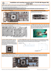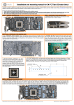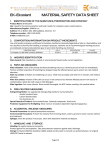
1
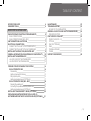
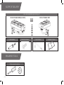
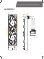
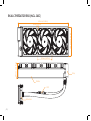
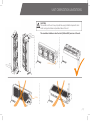
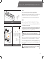
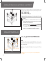
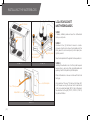
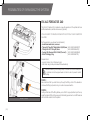
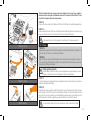
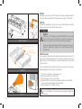
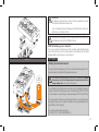
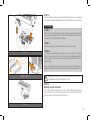
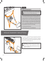
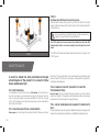
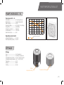
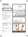
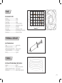
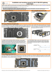
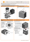
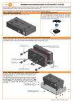
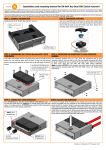
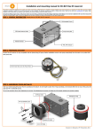
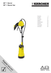
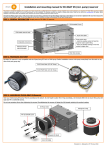
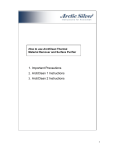
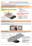
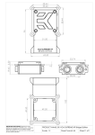
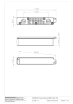
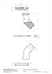
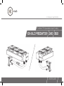
2nd Revision, Sep 18th 2015
Pre-filled CPU Xpandable Liquid Cooling
EK-XLC PREDATOR 240 360
USER GUIDE
EK Water Blocks bears the name of its founder Edvard König, who
started experimenting with liquid cooling in 1999. From the humble beginnings in the early years of the previous decade, the company grew
steadily to become a global premium liquid cooling gear manufacturer.
Today, EKWB offers a complete range of products for liquid cooling,
from a renowned Supremacy line of CPU water blocks, to a wide range
of CoolStream radiators, from in-house developed Vardar High pressure
fans, to market-proven DDC series of liquid cooling pumps and thus
provides overclocking enthusiasts and PC builders with the best of what
the market can offer. Predator all-in-one eXpandable Liquid Cooling solution is the next step to bring extreme liquid cooling performance in the
hands of dedicated gamers and PC enthusiasts around the world.
Welcome to EK-World!
Safety precautions
1. Keep and store the product away from the reach of children.
2. Check the component list and condition of the product before installation.
If there is any problem, contact the shop where you have purchased the
problem to get a replacement or refund.
3. EKWB d.o.o. is not responsible for any damages due to external causes,
including but not limited to, improper use, problems with electrical power,
accident, neglect, alteration, repair, improper installation and improper testing.
4. CPU and motherboard are subject to damage if the product is incorrectly
installed.
5. This product is All-In-One eXpandable CPU liquid cooling solution.
Disassembling it and combining with parts, other than EK Water Blocks
products, may lead to warranty loss.
6. Product warranty period is 24 months.
/2/
TABLE OF CONTENT
SCOPE OF DELIVERY
REQUIRED TOOLS
4
4
QUICK INSTALLATION GUIDE
RADIATOR SPACE CONSTRAINT REQUIREMENTS
EK-XLC PREDATOR 240
EK-XLC PREDATOR 360 (INCL. QDC)
UNIT ORIENTATION LIMITATIONS
ELECTRICAL CONNECTIONS
CONNECTING THE HUB TO THE POWER SUPPLY
CONNECTING THE HUB TO THE MOTHERBOARD
INSTALLING THE PUMP/FAN/RADIATOR UNIT
GENERAL INFORMATION ON WATERBLOCK COMPATIBILITY
INSTALLING THE WATERBLOCK
LGA-2011(-3) SOCKET MOTHERBOARDS
LGA-115X SOCKET MOTHERBOARDS
5
5
6
7
8
8
8
9
10
10
10
12
POSSIBILITIES OF EXPANDING THE SYSTEM
EK-XLC PREDATOR 240
Disassembly
Adding components to the loop
Filling up the system
Adding an external reservoir (OPTIONAL)
EK-XLC PREDATOR 360 (INCL. QDC)
Preparing the predator unit
Connecting the pre-filled water block/radiator unit
Adding an external reservoir (OPTIONAL)
INSTALLING TRANSPARENT TUBING (OPTIONAL)
REPLACING MOUNTING SCREWS FOR LGA-2011(-3)
MOTHERBOARDS WITHOUT MOUNTING HOLES (OPTIONAL)
14
14
14
15
15
17
18
18
19
20
20
MAINTENANCE
TROUBLESHOOTING
IN CASE OF CPU OVERHEATING
GENERAL LIQUID COOLING PARTS CLEANING GUIDE
PREVENTIVE STEPS
PART SPECIFICATION LIST
PUMP XYLEM DDC – 3.1
FITTINGS
FAN SPLITTER HUB
FANS
THERMAL GREASE
TUBING
SUPPORT AND SERVICE
22
23
23
24
24
25
25
25
26
27
27
27
28
21
/3/
SCOPE OF DELIVERY
All-in-one expandable liquid cooling unit
EK-XLC Predator 360 (incl. QDC)
Thermal paste
REQUIRED TOOLS
Phillips-head screwdriver
/4/
Mounting screws
OR
EK-XLC Predator 240
Torx T20 key
Installation manual
RADIATOR SPACE CONSTRAINT REQUIREMENTS
EK-XLC PREDATOR 240
133 mm (5,24 in)
120 mm (4,72 in)
295 mm (11,61 in)
15 mm (0,59 in)
Pump
Water block
Radiator
68 mm (2,68 in)
/5/
EK-XLC PREDATOR 360 (INCL. QDC)
133 mm (5,24 in)
415 mm (16,34 in)
15 mm (0,59 in)
68 mm (2,68 in)
120 mm (4,72 in)
Pump
Radiator
QDC
Water block
/6/
UNIT ORIENTATION LIMITATIONS
CAUTION:
The orientation of the unit is very important as wrong installation may lead to insufficient cooling performance and premature failure of the unit.
The orientation limitations stand for both (240 and 360) versions of the unit.
Pump
Pump
/7/
ELECTRICAL CONNECTIONS
CONNECTING THE HUB TO THE POWER
SUPPLY
STEP 1.:
Take the enclosed power cable and plug the two-pin PCI-express minifit power
connector to the fan splitter hub.
STEP 2.:
STEP 1
STEP 2
Use the SATA POWER connector at the other end and plug it to the female
connector found on the main power supply.
CONNECTING THE HUB TO THE
MOTHERBOARD
In order to obtain the PWM fan speed control you must follow the steps below:
STEP 3.:
Take the enclosed connection cable and plug the two-pin cable connector to
the fan splitter hub.
STEP 4.:
STEP 3
STEP 4
Use the 4-pin connector at the other end and plug it to the male connector
header located on the motherboard. Always use CPU-dedicated fan headers
if possible.
Always use CPU fan header. On majority of motherboards these
headers usually offer best PWM regulation.
/8/
INSTALLING THE PUMP/FAN/RADIATOR UNIT
STEP 1
Mounting of the pump/fan/radiator unit requires special attention.
Please take the unit and find the enclosed standard fan mounting screws. You
will need 8 screws for 240mm version or 12 screws for 360mm version.
You will need a philips-head screwdriver which is not enclosed in the package.
STEP 2
Prepare your suitably-sized PC chassis for installation of EK-XLC Predator.
STEP 1
The position of the unit in the chassis depends on the size, fan mounting holes
and the hardware you have installed.
You must make sure that the unit fits into the chassis. Usually the chassis have
standard fan mounting holes pre-drilled so you should look for holes with spacing of 105mm. (A standard computer cooling 120mm fan)
It is essential to install the radiator unit in well-perforated location
within the PC chassis thus ensuring the unit is well ventilated.
STEP 3
When you have selected the mounting position within the chassis you must
align the Predator cooling fan mounting holes with the ones on the chassis.
Use enclosed self-tapping screws to firmly install the unit. Self-tapping screws
require more torque than threaded screws, but overall do not exaggerate with
the force applied.
STEP 2
STEP 3
Check again that the unit isn’t touching the chassis anywhere except
at the mounting region. Some unwanted noise may occur if the vibrations are transferred from the unit to the pc chassis.
/9/
GENERAL INFORMATION ON WATERBLOCK COMPATIBILITY
This CPU liquid cooling unit is pre-assembled for use with modern Intel desktop socket
type motherboards. By default this water block supports the following CPU sockets:
- Intel® Socket LGA-115x
- Intel® Socket LGA-2011(-3)
The backplate and the BAS gasket are used just for mounting on the LGA-115x sockets!
Caution:
Not compatible with with LGA-2011-3 motherboards that do not have
mounting holes through the circuit board (e.g. some ASRock and Gigabyte
motherboards. Check before purchase!*
Narrow server type LGA-2011 is not supported by default – a Mounting plate
Supremacy LGA-2011 Narrow ILM (EAN: 3830046990600) is mandatory to install this water block on narrow server type LGA-2011 motherboards.
Replacing the mounting plate requires disassembly of the waterblock.
INSTALLING THE WATERBLOCK
LGA-2011(-3) SOCKET MOTHERBOARDS
STEP 1
Unscrew all four (4) thumb-nut screws (marked ORANGE) in counter-clockwise direction and remove the backplate and the BAS gasket. Do not use any tools (such as
pliers) during this process!
Supremacy
MX backplate
BAS gasket
STEP 1
/ 10 /
Store away the EK-Supremacy MX Backplate as it is not needed with LGA-2011 series
CPUs.
* Additional LGA-2011 specific mounting screws can be purchased separately.
See page 21.
STEP 2
Cleaning the CPU: Wipe the CPU’s contact surface (by using non–abrasive
cloth or Q-tip, as shown on sample photo).
Th
er
m
al
gr
ea
se
Non-abrasive
cloth
IHS
Applying thermal compound: EK recommends blob or line method of applying
the enclosed EK-TIM Ectotherm thermal compound to the CPU heat spreader
(IHS) - see sample photo on right.
The quantity of about two rice grains is just about right. There is no
need to cover the whole IHS. Applying too much thermal grease will
have negative impact on the cooling performance!
STEP 3
STEP 2
Align water block with pre-installed mounting mechanism above the LGA-2011
motherboard with pre-installed CPU.
Tighten the screws with your thumbs until you reach the end of the thread, preferably by tightening two thumb screws at a time in the cross pattern. Do not use
any tools (such as pliers) during this process!
Your EK-XLC Predator installation on LGA-2011(-3) platform is now complete.
Starting your computer up:
Before you add the power to your computer please check if everything
is installed according to the installation manual.
When turning on the computer be careful nothing is leaking and that the
temperatures of the CPU are normal. It is best practice to enter BIOS/
UEFI and check hardware health monitoring section on initial boot!
STEP 3
/ 11 /
INSTALLING THE WATERBLOCK
LGA-115X SOCKET
MOTHERBOARDS
PC chassis
STEP 1
If already installed, please remove the motherboard
from your computer.
Motherboard
STEP 2
BAS gasket
Supremacy
MX backplate
Save the backplate and the gasket for later operations.
STEP 2
STEP 1
Unscrew all four (4) thumb-nut screws in counterclockwise direction and remove the backplate and the
BAS gasket. Do not use any tools (such as pliers) during this process!
STEP 3
Installing this water block on LGA-115x system requires
two pre-steps – removing of the original Backplate and
replacing it with EK-Supremacy MX Backplate.
Place motherboard on an even surface with front side
facing up.
ILM Backplate
Torx T20 key
Socket latch
Motherboard
STEP 3
/ 12 /
Using enclosed Torx key T20 remove the three UNC
6-32 screws securing the Socket Latch Mechanism
(ILM) and original backplate (BP) to the motherboard.
See sketches on the right (STEP 1, STEP 2, STEP 3)
for part identification.
STEP 4
Replace the original ILM backplate with the enclosed EK-Supremacy MX Backplate and BAS gasket and then secure it using three original UNC 6-32 screws.
Supremacy MX
Backplate
Torx T20 key
BAS Gasket
Socket latch
Motherboard
STEP 4
BAS gasket is needed to prevent short-circuit between the backplate
and the motherboard therefore it is mandatory to install it!
STEP 5
Cleaning the CPU: Wipe the CPU’s contact surface (by using non–abrasive
cloth or Q-tip, as shown on sample photo).
Applying thermal compound: EK recommends blob or line method of applying
the enclosed EK-TIM Ectotherm thermal compound to the CPU heat spreader
(IHS) - see sample photo on right.
The quantity of about two rice grains is just about right. There is no
need to cover the whole IHS. Applying too much thermal grease will
have negative impact on the cooling performance!
er
m
al
gr
ea
se
Non-abrasive
cloth
Th
IHS
STEP 6
Align water block with pre-installed mounting mechanism above the LGA-115X
motherboard with pre-installed CPU.
STEP 5
Tighten the screws with your thumbs until you reach the end of the thread,
preferably by tightening two thumb screws at a time in the cross pattern. Do not
use any tools (such as pliers) during this process!
Your EK-XLC Predator installation on LGA-115X platform is now complete.
Starting your computer up:
Before you add the power to your computer please check if everything is installed according to the installation manual.
STEP 6
When turning on the computer be careful nothing is leaking and that the
temperatures of the CPU are normal. It is best practice to enter BIOS/
UEFI and check hardware health monitoring section on initial boot!
/ 13 /
POSSIBILITIES OF EXPANDING THE SYSTEM
EK-XLC PREDATOR 240
The EK-XLC Predator 240 is capable to cope with expansion of the system with one
additional waterblock, radiator and reservoir (optional).
YOU MAY NEED TO REMOVE COMPLETE UNIT FROM YOUR COMPUTER
CHASSIS!
For the expansion you will need (recommended):
- A additional waterblock/reservoir
- Tubing: EK-Tube ZMT Matte Black 15,9/9,5mm
- Fittings: EK-ACF Fitting 10/16mm
- Coolant: EK-Ekoolant EVO CLEAR (Premix 1l)
- EK-ATX Bridging Plug
(EAN: 3830046999207)
(EAN: 3831109846452)
(EAN: 3830046999689)
(EAN: 3831109867716)
Required tools:
- A pair of scissors (to cut the tube to size)
- 6mm Allen key (usually enclosed with the waterblock)
Before undertaking the following steps it is advised to have a suitable plastic container and some paper towels on hand in order to prevent coolant
spillage
STEP 1.:
1
2
STEP 1 and 2
/ 14 /
We recommend that you drain the loop through the fitting on the CPU waterblock.
Unscrew the fitting compression ring in counter-clockwise direction.
STEP 2.:
Gently pull the tube off the fitting. Before you do that it is a good practice to put the cup
under the tube and fitting for the purpose of safe draining procedure. You can tilt the whole
unit to let all the coolant out of the system.
Take the additional liquid cooling component (water block of any type, radiator...)
and mount it according to its installation manual. To connect it to the EK-XLC Predator 240 unit please follow the steps below:
STEP 3.:
Connect the loose tube from Predator unit to the 10/16 fitting on the additional water block.
STEP 4.:
Nut
Barb
STEP 3 and 4
Make sure that the tube sits firmly on the fitting barb and then tighten the compression ring
using your hands only. Do not use any tools (i.e. pliers) during this process.
If the present tube is not long enough you will have to cut a new-longer one.
OPTIONAL
STEP 5.:
Measure the length of the tube that is needed to connect the water blocks together. You
can use a pair of scissors or a knife to cut the tube.
STEP 6.:
Attach the tube onto the both fitting barbs until it sits firmly. Secure the fitting’s compression ring to make the assembly complete. Check again that all of the tubing is secured by
compression fittings as intended.
Filling up the system:
Before starting to fill the system you should prepare some paper towels in case of
dripping. In order to fill up successfully please follow the steps below.
STEP 5 and 6
STEP 7.:
Use 6mm Allen key (supplied with every EK water block) to unscrew the plug on the backside of the Predator unit radiator.
STEP 8.:
Start filling process by adding coolant through the port on the back of the unit as shown
on the picture on STEP 8. Pour the coolant slowly until the unit is full then shake it a bit to
get out as much air as possible. You can alternatively screw the plug in and rotate the unit in
multiple directions and then repeat the procedure until there is no air left in the unit.
STEP 7 and 8
It is essential to get as much air as possible out of the system at this stage!
/ 15 /
STEP 9.:
Reinstall the plug, removed in STEP 7 using 6mm Allen key. Afterwards place the
unit on the firm surface with fans facing upwards as pictured in STEP 9 and 10
STEP 10.:
Unscrew the integrated reservoir plug in counter-clockwise direction using 6mm
Allen key. Add more coolant until the unit seems full.
OPTIONAL
STEP 11.:
Plug in the EK-ATX Bridging Plug (EAN 3831109867716) to your male
24-pin ATX PSU cable to jump-start your computer. It is a good practice to also unplug the fans from the fan splitter hub (see page 8).
STEP 9 and 10
Make sure nothing except the fan splitter hub is plugged to the power
supply. All motherboard-, graphics card- or SATA power should be
disconnected!
Power supply ATX cable
EK-ATX
Bridging Plug
STEP 12. and 13:
Upon powering up the Predator the coolant level will most likely drop and the unit
(namely pump) might operate loudly. This is caused by air still present in the loop.
When it does you must add additional coolant until the liquid line is clearly visible
and the unit is full.
STEP 11
The air is being bled from the system as the pump is running. The procedure for
assisted bleeding air from the system is as following:
1)
2)
3)
4)
Coolant
STEP 12
/ 16 /
Turn off your computer (or power supply unit)
Add more coolant to the unit (top it off)
Turn the power on, let it run for 5 minutes
Shake and tilt the unit to force the remaining air bubbles out. Reinstall the
plug to prevent coolant spillage during this substep.
5) Repeat substeps 1 to 4 until the unit is full
Once the rattling diminishes this is a good sign that the loop is free
of air. The installation of an additional reservoir greatly simplifies this
procedure.
STEP 14.:
It is always a good practice to conduct a 24-hour leak test to ensure
the system is leak free and safe to use.
Upon completing the leak test please reinstall the liquid cooling unit
back into your computer chassis.
Before you add the power to your computer please check if everything
is installed according to the installation manual.
STEP 15: Starting up your computer
Turn on your computer. When turning on the computer check that the temperatures of the CPU are normal. It is best practice to enter BIOS/UEFI and check
hardware health monitoring section on initial boot!
STEP 14
OPTIONAL
Adding an external reservoir:
In order to make the refilling process of the unit easier after the expansion it is
recommended to install an additional external reservoir.
To achieve the best flow balance in the loop it is mandatory to mount
the reservoir on the last stage before the liquid enters into the
pump/radiator unit – as shown on the picture.
It is mandatory to install the reservoir according to its installation manual. In
order to connect it to the existing loop you should follow the STEP 1 to STEP
12 in this chapter. You should fill your reservoir between STEP 7 and STEP 8.
It is a good practice to fill your loop at the highest point. In our case that means
through the reservoir or through the chamber on the pump/radiator/fan unit
(see STEP 8. of this chapter)
In our case we have added a reservoir:
EK-RES X3 250 – EAN (3831109841020)
/ 17 /
POSSIBILITIES OF EXPANDING THE SYSTEM
EK-XLC PREDATOR 360 (INCL. QDC)
The EK-XLC Predator 360 (incl. QDC) is capable to cope with expansion of the
system with additional 2 (two) waterblocks and 1 (one) radiator.
There is no need to unmount the unit from the chassis unless you have some
tube-routing constraints. Because of the no-spill quick disconnect connector couplings the expansion is very quick, easy and safe when using QDC-enabled water
blocks.
For the expansion you will need:
- A new pre-filled waterblock or radiator
Required tools (in case of need to refill the loop):
- 6mm Allen key (usually enclosed with the waterblock)
- ATX Bridging plug
(EAN: 3831109867716)
STEP 1.:
Turn off your computer and unplug the computer from power.
2
1
STEP 2.:
Disconnect the QDC installed on the EK-XLC Predator 360 unit. First you need
to press on the button on the QDC to release (disconnect) the mechanism which
holds it together. After that you should gently pull it apart and you are done.
STEP 1 and 2
STEP 3.:
Mount the pre-filled water block/radiator according to its installation manual.
Male QDC
Female QDC
STEP 3 and 4
/ 18 /
STEP 4.:
Route the tubes in the way that the QDC’s can be connected with the present
ones on the EK-XLC Predator 360 (incl. QDC). Be careful not to make contact
with the hardware as the metallic tube clamps can short electrical component.
The tubes should be long enough to do so.
STEP 5.:
Connect the QDC couplings according to the sketch on the right. You wil feel the
locking click sound when assembled correctly. The installation is now complete.
OPTIONAL
STEP 6.:
Plug in the ATX bridging plug. Make sure nothing except the fan splitter hub
is plugged to the power supply. You must also unplug the fan and the PWM
connectors from the fan splitter hub (Page 8)
STEP 7.:
Turn the power supply on and check that only the pump is running.
STEP 5
Power supply ATX cable
EK-ATX
Bridging Plug
STEP 8.:
It is always a good practice to conduct a 24-hour leak test to ensure the
system is leak free and safe to use. Once the test is complete power off the
power supply unit and remove the EK-ATX Bridging Plug from the main 24pin ATX cable.
Upon completing the leak test you can safely reconnect all motherboard-,
graphics card- and SATA power cables. Your computer is now ready to use.
STEP 6 and 7
Before you add the power to your computer please check if everything
is installed according to the installation manual.
STEP 9:
Starting up your computer
Turn on your computer. When turning on the computer check that the temperatures of the CPU are normal. It is best practice to enter BIOS/UEFI and check
hardware health monitoring section on initial boot!
STEP 8
/ 19 /
OPTIONAL
Adding an external reservoir:
In order to make the refilling process of the unit after the expansion
easier it is recommended to install an additional reservoir.
To achieve the best flow balance in the loop it is mandatory to install the reservoir on the last stage in before the water enters the pump/radiator/fans unit –
as shown on the picture. You must install your reservoir according to its installation manual. In order to connect it to the existing loop please follow STEP 1
to STEP 9 of the expansion. You should fill your reservoir between STEP 5
and STEP 6 in this chapter. It is a good practice to fill your loop at the highest
point. In our case that means through the reservoir or through the chamber on
the pump/radiator/fan unit (see STEP 8. in this chapter)
In our case we have added a reservoir:
EK-DBAY Spin Reservoir (R3.0) - EAN 3831109840849
INSTALLING TRANSPARENT TUBING (OPTIONAL)
When changing the original EK ZMT tubing for transparent tubing (PrimoChill
PrimoFlex™ Advanced LRT™ 9,5 mm (3/8”) / 15,9 mm (5/8”) - Crystal Clear
tube) or equivalent it may happen that the coolant evaporates through the tubing
walls due to PVC material being slightly porous.
IMPORTANT: When replacing original EPDM rubber tubing for PVC
tubing it is mandatory to check for cooling liquid level on a regular basis.
EK highly recommends installing additional external reservoirs when
replacing the original tubing.
/ 20 /
REPLACING MOUNTING SCREWS FOR LGA-2011(-3) MOTHERBOARDS
WITHOUT MOUNTING HOLES (OPTIONAL)
The CPU water block on the Predator unit isn’t compatible with LGA-2011
motherboards that do not have mounting holes through the circuit board
(e.g. some ASRock and Gigabyte motherboards).
Normal (factory provided)
mounting screw
LGA-2011 Specific
mounting screw
Difference
In order to install the CPU water block on such motherboards you
must replace the mounting screws with screws:
EK-XLC Predator LGA-2011 Screw Set (EAN 3831109800348)
Please follow the steps below:
STEP 1.:
Unscrew all four (4) thumb-nut screws in counter-clockwise direction and
remove the backplate and the BAS gasket. Do not use any tools (such as
pliers) during this process!
Store away the EK-Supremacy MX Backplate as it is not needed with LGA2011 series CPUs.
BAS gasket
Supremacy
MX backplate
STEP 2.:
Removing the factory-installed mounting screws.
In order to replace the mounting screws you will need to remove the four
metal circlips, that are securing the screws to the mounting plate.
Take the (electrician) pliers, grab the circlip and pull it off the screw.
STEP 1
Metal circlip
Pliers
Pull the circlip from the screw as shown on the picture on the left.
opening must be facing in counter direction to the pliers grab side.
Store the original mounting screws away as they will not be needed anymore.
Pliers
Metal circlip
The metal springs will be reused.
STEP 2
/ 21 /
STEP 3.:
Installing LGA-2011 Specific mounting screws.
Take the metal springs and put them over LGA-2011 Specific mounting
screws. Guide the screw ends through the holes in the mounting plate of the
CPU water block.
It is a good practice to reinstall the circlips onto the new mounting
screws so you get a fixed mounting mechanism.
Your CPU water block is now ready to be installed on the LGA-2011
motherboards that do not have mounting holes through the circuit
board.
STEP3
To install the CPU water block please follow the instructions on page 8, from
STEP 1 forward.
In order to obtain the best performance through
whole lifespan of the product it is crucial to follow
these maintenance tips:
they should. The pump and fans must run silently without any rattling noises
and must react to PWM duty cycle changes.. All imperfections may lead to
overheating and breakdown.
MAINTENANCE
TIP 1: DUST REMOVAL
It is mandatory to remove the dust every 2-3 months. EK recommends to
use a vacuum cleaner or compressed air to blow the dust away. The most
dusty is usually the radiator so pay special attention to that. Do not forget
to turn off the computer and unplug the power supply. It is recommended to
remove the dust outside.
Every 3 years the unit should be thoroughly cleaned. You must let all the
coolant out (Page 14). The radiator must be flushed and the pump checked
and cleaned. It is recommended to change the tubing.
TIP 2: CHECKING ELECTRICAL COMPONENTS
It is recommended to use only genuine EK Water Blocks liquid cooling gear, parts
and add-ons to prevent any performance, compatibility and warranty issues.
Once a year you should check the pump and the fans, if they are running as
/ 22 /
TIP 3: CLEANING THE UNIT (RELATED TO CHAPTER
TROUBLESHOOTING)
TIP 4: USE EK DESIGNED AND MANUFACTURED PARTS
ONLY
TROUBLESHOOTING
IN CASE OF CPU OVERHEATING:
Very high CPU temperatures are usually the symptoms of malfunctioning
liquid cooling loop, assuming the contact between CPU heat spreader and
water block itself is good and that the water itself is adequately cooled within
the radiator. This can occur either due to:
1. Malfunctioning or non-working water pump: The symptoms usually
include rapid spike in temperature when stressing your CPU to the maximum (for example with Prime95 software). Make sure the pump is plugged
in to the power connector and that the liquid is indeed flowing in your system. You should feel the pump vibrating in your hand. Observe the flow
indicator or flow meter reading if present.
2. Malfunctioning or non-working cooling fans: The symptomes
usually include rapid spike in temperature when stressing your CPU to the
maximum. Make sure the cooling fans are pluged in to the power connector hub and that the blades are indeed rotating.
3. Kink in the liquid cooling tubing: Very similar symptoms to both above
described. Thin-walled tubing may collapse easily under low radius turns or
when obstructed by other computer chassis elements such as closing side
panel doors. Check the tubing for any signs of kink which restrict the flow.
This is normally not the case when using original tubing.
5. Thermal interface material (paste/grease) not applied or appied
improperly: Lack of - or even too much TIM - may result in CPU overheating. Please refer to STEP 2 in INSTALLING THE WATER BLOCK
section.
Another culprint could be partially or completely defective CPU. Some CPUs
runs at higher temperatures than the others. Overheating of the CPU can also
occur due to:
1. Poor thermal contact within the CPU itself: Some CPUs, such as Intel
LGA-1151 socket based Skylake, Intel LGA-1150 based Haswell and older,
socket LGA-1155 based Ivy Bridge are notorious for their poor thermal contact between the CPU die and the heat spreader (IHS) itself due to the use
of poor TIM. This is the problem of the processor and not the Predator CPU
liquid cooling unit. These CPUs are known to run very hot (80°C+) even on
factory set frequencies. For best performance it is usually recommended to
replace the TIM between the die and the IHS or to even run the processor
de-lidded. Both require hazardous IHS removal which voids processor’s
warranty but can lead to temperature decrease of 30°C and higher.
Upon exhausting all optiones please consult EK knowledge base
at http://support.ekwb.com . Raise a question through EK Support
ticketing system if needed.
4. Clogged microchannels in the water block: Microchannels can get
clogged easily with various dirt particles and impurities, especially with
plasticizer powder which has leached from the tubing (When using unsafe liquid cooling tubing). The symptoms usually include rapid spike in
temperature when stressing your CPU to the maximum, flow rates are
very low. Visually inspect the water block internals for any buildup or contamination and clean the system if necessary. In case the water block with
translucent acrylic top is employed this inspection can be done without
disassembling the system.
/ 23 /
GENERAL LIQUID COOLING PARTS CLEANING GUIDE
Liquid cooling parts may be disassembled for cleaning purposes
on an occasional basis. Your warranty is not voided on disassembly of the water block but the customer loses the EK leak-free guarantee which comes with a factory tested Component. And old, but
soft toothbrush is an excellent cleaning tool!
1. Cleaning bare copper: When cleaning bare copper is it recommended to
use slightly acidic cleaning agents which include the following organic agents:
- (white) vinegar (acetic acid up to 5-10%)
- lemon juice (citric acid up to 5-10%)
Certain food can also be used for cleaning copper:
- cola (contains phosphorous- and citric acid)
- ketchup or tomato extract (contains acetic- and citric acid)
- mustard (contains acetic acid)
5% vinegar , dilluted with 95% water is enough to kill 99.9% of algae
and bacteria that could be present on copper in an unmaintained
cooling loop as well.
Upon cleaning is it necessary to flush the water blocks in water and rinse them
with distilled water. After rinsing we recommend soaking the water blocks in
paper towels until completely dry. It is nearly impossible to avoid the naturally
occurring copper tarnishing (oxidation) as the oxidation will reoccur the moment the copper is cleaned of the all oxides.
2. Cleaning nickel plated copper: When cleaning nickel plated copper it is
forbidden to use any aggressive chemicals (neither vinegar) or rough materials as you may damage the plating and thus void the warranty. Please note
also that due to presence of dye additives and other chemicals the nickel layer
may also become discolored/stained over time period. However the staining
is normally reversible by simple flush and rinse. Cleaning the nickel plated copper should consists of these steps:
- flush the nickel plated copper under warm water
- clean the surface using wet non-abrasive cloth and rinse with clean water
- polish the hardened deposits (such as algae or dirt) from the nickel plated
copper if necessary.
/ 24 /
EK recommends the use of automotive soft, non-abrasive metal polish
cremes. After you finish using other cleaning methods, give the nickel plating a good polish with a non-abrasive metal or chrome polish. Apply a small
amount of polish to a cloth or to the surface of the nickel. Wipe the entire
surface of the nickel with the polish, using small circular motions, until it looks
shiny and clean. Use another clean cloth to remove the remains of the polishing paste from the surface. Always rinse with distilled water after you are done
with polishing.
3. Cleaning acrylic (plexi) glass tops: Acrylic will fail prematurely if subjected to even small amounts of alcohol, acetone or other aggressive chemicals.
Please do not use anything but warm, soapy water and a toothbrush to clean
the acrylic (plexi) glass water block tops and reservoir tubes. Using aggressive chemicals will surely void your warranty!
Algae- or dirt deposits may be rubbed out using soft cloth in combination with warm, soapy water. Rinse with distilled water after
cleaning.
4. Cleaning POM (acetal) tops: POM (polyoxymethylene) or Acetal can
withstand chemicals such as alcohol or acetone but EK recommend to use
these very sparingly as the drying chemicals will surely leave some residue.
Usually the POM can be cleaned easily just be the use of soft cloth and
warm, soapy water - without the use of any chemicals. Rinse with distilled
water after cleaning.
PREVENTIVE STEPS:
1. Using corrosion inhibiting coolant (such as EK-Ekoolant or other
market proven coolant) is highly recommended for any water cooling loops.
Since EK-Ekoolant is also a surfactant is will prevent algae growth and dirt
deposition on all wettered surface.
2. Refrain from using Copper Sulphate based additives in your loop in order
to prevent tarnishing on your water cooling gear internals!
PART SPECIFICATION LIST
PUMP XYLEM DDC – 3.1
Pump Xylem DDC - 3.1
7,0
1,80
1,60
6,0
1,40
5,0
1,20
1,00
4,0
0,80
3,0
0,60
Power (W)
Height (m)
Pump Type ................................................ DC centrifugal Pump
Bearing Type............................................ Ceramic Bearing Ball
Rated Voltage ....................................... 12VDC
Operating voltage ............................... 8*-13,2VDC *9v starting
Pump RPM ............................................. 3000RPM
Dimensions (LxWxH) ..................... 61x60x21
Life Expectancy .................................... >50 000h
Max head of pump ............................. 1,6m
2,0
0,40
Operating environment
Ambient temperature ....................... 10-50°C
Fluid temperature(coolant).......... 10-60°C
0
50
100
150
200
250
Volumetric flow rate (l/h)
H(Q)
P(Q)
FITTINGS
Fittings
Type.................................................................. 2x Compression
Type.................................................................. 2x Rotary Compression
Compatible tubing (metric) .......... 9,5 mm / 15,9mm (ID/OD
Compatible tubing (imperial) ..... 3/8’’ – 5/8’’ (ID/OD)
Thread size ................................................ G1/4”
Material ......................................................... Brass
Coating .......................................................... Nickel
Rotary
compression fitting
Compression fitting
/ 25 /
FAN SPLITTER HUB
To the Power supply unit
Fan splitter hub
All the elements that need electricity to run are connected to the
fan splitter hub, located on the bac k of the unit.
This fan splitter hub contains three 4-pin PWM Fan
headers for three fans and one pump.
Pump
Fan 3
(Predator 360 only)
Fan 2
Fan 1
A two-pin header is used to connect Predator unit to motherboard CPU Fan header in order to allow for speed regulation
of fans and pump. 2-pin PCI-express miniFIT power header is
used to provide power to Predator unit.
General characteristics:
- 3x 4-pin PWM fan header (Molex KK 254 standard)
- 1x 4-pin PWM pump header (Molex KK 254 standard)
- 1x 2-pin tacho/PWM header (Molex KK 254 standard)
- 1x 2-pin power header (Molex miniFIT standard)
- 1x Power LED indicator diode (red)
- Rectified PWM input
- Uniform PWM control on all headers
RPM (tacho) and
PWM header
Pump
header
Fan 1/2/3 header
Power
LED light
Unit main power
header
Connecting the pump directly to motherboard
fan header (OPTIONAL)
If you want to control the speed of the pump and the fans separately you should follow the steps below:
STEP 1.:
Disconnect the pump’s cable from the fan splitter hub. You will
need to remove cable ties in order to do so.
STEP 2.:
Connect the pump’s connector to the CPU fan header (preferably) on the motherboard.
/ 26 /
STEP 1
STEP 2
25
FANS
EK-Vardar F4-120
Fan type..............................................................PWM
Rated Voltage ...............................................12 VDC
Power Draw ....................................................2,16W
Max Air Flow .................................................. 77 CFM = 131 m³/h
Static Pressure ............................................3.16mm H2O = 31 Pa
Noise Level .....................................................33.5 dBA
Max speed .......................................................2200 rpm (+/- 10%)
Life Expectancy ..........................................50.000 hrs @ 40°C (MTBF)
Dimensions.....................................................120 x 120 x 25 mm
Pressure - Pa
20
15
10
5
0
0
20
40
60
80
100
- m3/h
120
140
THERMAL GREASE
EK-TIM Ectotherm
Type.......................................................................Low Viscosity
Electrically conductive..........................No
Optimal working temperature........+100 to -50(°C)
Thermal conductivity.............................8,5 W/mK
Density ...............................................................3 g/cm3
TUBING
EK-Tube MT Matte Black 15,9/9,5mm
Material ..............................................................EPDM
Color .....................................................................Black, not UV-reactive
Operating temperature range........-30°C to 110°C
Dimensions....................................................9,5mm/15,9mm (ID/OD)
/ 27 /
SUPPORT AND SERVICE
For assistance please contact:
http://support.ekwb.com/
[email protected]
EKWB d.o.o.
Pod lipami 18
1218 Komenda
Slovenia - EU