1
Lab 8 – Problem Solving Lab Procedure
It is expected that you have already read the Problem Solving Lab Project Description Document.
Before starting a Task, read through the instructions for the entire task. This will help you
understand what you are going to accomplish during that Task.
Getting Started
1.
2.
3.
4.
5.
6.
7.
Plug the 12 Volt Power Module into the power strip on the table and make sure the power strip is
“on”.
Plug the barrel connector on the wire from the 12 Volt Power Module into the mating connector
located at the outside edge of the Train Project Setup.
Connect the USB Cable from the Train Setup to a USB port on the front of your computer.
Confirm that the red LEDs on the Break Beam Sensors are on. Also, confirm that the yellow
LED on the Arduino board is also on. If any of those lights are not on, get help from your
instructional team.
Go to LAB 8A on the course website and locate the link to the Zip file for the MATLAB Train
Simulator. This contains the files needed to communicate to the Train.
5.1 Right Click the link and select “Save Link as…”
5.2 Save the file to your MATLAB folder on you Z:/ drive.
5.3 Open your MATLAB folder and locate the Zip file you just downloaded.
5.4 Right click on the file, select “Extract all…” and click “Extract” on the pop up window.
5.5 Rename the extracted folder to “Lab_8_Train_Project”.
Open MATLAB and change the Current Directory to the recently created
“Lab_8_Train_Project” folder.
Download and save the “Problem_Solving_Lab_Worksheet” from the website to your
“Lab_8_Train_Project” folder.
Task 1: Connect your PC to the Arduino
1.
Open Windows Device Manager :
1.1 Click “Start” on the bottom left toolbar on your Windows desktop.
1.2 In the search box at the bottom, type “Device Manager” and press the enter key. Click “OK”
on the error message.
2.
After the Device Manager opens, click the arrow next to “Ports (COM & LPT)”. This process
will cause the Arduino USB Drivers to be installed automatically on your PC. After the Arduino
USB Drivers have finished installing, you will see “Arduino Uno (COM#)” listed, where # is
number of the COM port to which the Arduino is attached.
3.
Write the number in the Problem Solving Lab Project Worksheet under Task 1 and close the
Device Manager.
4.
In the MATLAB command window, clear all variables and clear the command window by typing
the commands “clear all”, “close all”, and “clc” (hit “Enter” after each
command).
Note: Do not copy / paste any MATLAB commands from this procedure or from Word documents
– type them manually. MATLAB does not correctly interpret Word text formatting.
5.
6.
Next, enter the command “delete(instrfindall)”. This will clear any previous
Arduino connection.
In the MATLAB command window, type: “a=arduino('COM#')” where # is the COM
port number you found above, and hit “Enter”. For example, if your Arduino is connected to
COM3, type: “a=arduino('COM3')”.
Do NOT type the “arduino” command without assigning it to the variable “a” using the equals
sign. If you do, use the clear commands issued above in Steps 4 and 5
7.
8.
9.
10.
11.
MATLAB will attempt to connect to the Arduino.
If you get an error message, double check that you have followed the above steps exactly as
listed, repeating steps as necessary. If you try again and get the same message, ask a member of
the instructional staff for assistance.
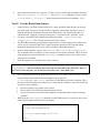
Examine the command window output. Notice how Servos are Detached and Digital Pins are
Unassigned. If you do not see the output: Repeat steps 4 - 5 and then repeat the command
“a=arduino('COM#')” without the semi-colon that suppresses output to the command
window.
If the connection is successful, a message will display “FE Train Shield Script File detected!”
Clear the command window with a “clc”.
Task 2: Set up the Servo motor that controls the crossing gate
1.
2.
Your gate servo is wired to servo port 1 on the Arduino controller.
To attach the servo to the Arduino, type the command “a.servoAttach(1)” and hit
“Enter”. This command must be issued every time the Arduino is reconnected.
Note: When using any Arduino command, it must be prefaced with “a.” (Note the period). This tells
MATLAB to perform the command on variable “a” which was created with the
“a=arduino(‘COM#’)” command. Also, Arduino commands are “CaSe SeNsItIvE”.
3.
4.
To check your servo, type the command “a.servoStatus”. And you see that servo 1 is
now attached – that means the Arduino can now tell it what to do.
To control the servo, use the command “a.servoWrite(X,θ)”, where X is the servo
number and θ is angle in degrees. This lab only uses servo number 1.
IMPORTANT: Always use a value of θ that is between 10 and 170 degrees. Using a value outside
of this range can damage the servo motor.
5.
Enter the command “a.servoWrite(1,165)”. The crossing gate should now be
approximately horizontal.
6.
Now experiment with angles between 50 and 80 to find the specific value of θ that makes your
crossing gate go vertical. Write the answer in the worksheet.
Task 3: Set up and test the Crossing Gate LEDs
1.
2.
3.
4.
5.
In order to control the Crossing Gate LEDs, the digital pins on the Arduino must be assigned a
mode (input or output) and a state (on or off). The LEDs on the crossing gate are attached to
digital pins 14 and 15 on the Arduino.
First the digital pins that control the lights must be set as outputs. This is done by typing the
commands “a.pinMode(14,'output')” and “a.pinMode(15,'output')”,
each followed by the “Enter” key. This command must be issued every time the Arduino is
reconnected.
To change the output state of digital pin 15, enter the command
“a.digitalWrite(15,1)”. One of the LEDs should now be on. Which LED? Record
the answer in the worksheet.
Logical 0 turns the LED off, and logical 1 turns the LED on. Use the command line to turn on
both LEDs. i.e.: “a.digitalWrite(15,0)” turns off digital pin 15.
You can assign the pin numbers to a MATLAB variable in order to keep track of which pin
controls which LED. To do this, you might enter the command “rightLED=15” then use the
variable rightLED in the digitalWrite command in place of the number 15. The new
command would be “a.digitalWrite(rightLED,1)”. Repeat with the left LED (use
“leftLED=14”)
Task 4: Move the Train
1.
2.
3.
Carefully place the train on the track at the location where the black piece of track has wires
connected to it from the Arduino. Look at the train wheels very carefully to be certain that all
train wheels are properly on the track. Check with the instructional team if needed.
The train has three states of motion: forward, backward, and release. Release is a command that
can be used to stop the train. To enable the train to move forward, type the command
“a.motorRun(1,'forward')”. Nothing happens until you set the speed in the next
command. This command must be issued every time the Arduino is reconnected.
To set the train speed, use the command “a.motorSpeed(1,S)”, where S is a value
between 0 and 255 as described below.
IMPORTANT: In order to overcome static friction, the engine motor requires a minimum value of
S before it will move. Therefore, the useable range for train speed is from S = 170 to S = 255. If
you set the train to move and you hear the motor whirring but there is no movement, immediately
pull the train off the track, set the motorSpeed to 0, and then try again with a larger value for S.
4.
5.
Use the command “a.motorSpeed(1,255)” to make the engine run at full speed. If it
does not run, alert an instructional team member.
Stop the train with “a.motorSpeed(1,0)”.
6.
Run it again at full speed (use “up-arrow” to retrieve previous MATLAB commands) and stop it
with “a.motorRun(1,'release')”. After a 'release' command, you must execute
“a.motorRun(1,'forward')” before entering new motor speed commands. Try it!
Task 5: Test the Break Beam Sensors
1.
2.
3.
4.
5.
Unlike the Servo, the LEDs, and the locomotive’s motor, the Break Beam Sensors do not need
any initial setup. The sensors will be called the “approach” gate and the “departure” gate (see
Problem Solving Lab Description Document for clarification). The Arduino analog port 2 is
connected to the “approach” sensor and analog port 3 is connected to the “departure” sensor.
For clarity, create MATLAB variables and assign them values: “approach=2” and
“departure=3”. This will help you keep track of the sensors.
The Break Beam Sensors send a numerical value (actually a scaled voltage) to the Arduino that
will be used by your MATLAB Train Control Program to determine if the Train has broken
through the optical path in the sensors. (Hence the name “Break Beam Sensor”).
In the command window, execute “approach=2” and “a.analogRead(approach)”.
The command window will display a value. Enter that value into the worksheet. This is the value
of the unobstructed sensor. Repeat the analogRead command at least 5 times. Enter 2 more
values into the worksheet.
Does there appear to be a pattern to the values? Answer.
Sometimes the “analogRead” command does not read a correct value at first. So when using
“analogRead”, take five readings, throw away the first four and use the fifth value. Hint: in
your Train Control Program, you can easily do this with a small “for-end” loop.
6.
Have a group member block the approach beam with his or her fingers. While blocked, verify that
the green LED on the sensor circuit board lights up. Once again, use
“a.analogRead(approach)” several times. Enter that value into the worksheet. This is
the value of the obstructed sensor. Enter 2 more values into the worksheet. Answer the following
questions in your worksheet:
•
Does there appear to be a pattern to the values?
•
How do these values differ from the unobstructed values?
•
Are the values always consistent? Why might this be important when it comes to writing a
program?
7.
When using the “analogRead” command in a MATLAB script file, you must execute it four
times before using the returned value. For example:
a.analogRead(approach);
a.analogRead(approach);
.......
if a.analogRead(approach)>250
...
end
For purposes of your Train Control Program, the Train is on the “Town Side” of the track layout when it
is in Crossing Gate portion of track that is between the Break Beam Sensors. The train is in the “Country
Side” of the track layout when it is not in the “Town Side”. Notice the green trees in the “Country Side”.
Task 6: Write a Train Control Program
1.
2.
In order to effectively control the train for an infinite period of time, an m-file should be used.
Open a new m-file in MATLAB. After putting your group name, individual names, and class
information at the top of the file, you should include the following commands.
clear all;
close all;
delete(instrfindall);
clc;
3.
4.
5.
The next command should be the command learned in Task 1 to connect to the Arduino.
Next you need to use the commands you have learn in Tasks 2 through 5 to initiate the
components you will need to use and create ‘start-up conditions.’
Insert an infinite while loop using:
while 1
% Infinitely Looping Code here...
end
Inside this loop you will write the remainder of the train control program for Task 7.
Task 7: Calculate the Train Speed
In Task 7, you will write a program to measure the speed of the train and record the results in the Problem
Solving Lab Worksheet.
Train Control Program Requirements:
•
•
•
Start the train on the “Country Side” of the track
Calculate the train speed between the “approach” sensor and “departure” sensor
Run the train at full speed (i.e. a.motorSpeed(1,255))
•
•
•
•
•
•
Write the calculated time and speed in an fprintf statement to the Command Window
Display the time in seconds for each half-loop
Display the speed in miles per hour AND inches per second
Repeat continuously until stopped manually
Do not use the “Pause” function.
Program MUST contain user-written comments.
If you are unable to complete Task 7 by the end of the Lab period you can use the supplied “Train
Simulator” to develop and test the code for Task 7. Instructions how to use the Train Simulator can be
found in the document “Train Simulator Student User Manual.docx” located in the
“Lab_8_Train_Project” folder created at the beginning of this procedure. The Simulator can only be
used to test that your code works properly, you will have to record the actual speed data during LAB 8B.
Useful Information
•
•
•
•
•
•
•
•
•
Use ‘CTRL+C’ on the keyboard to stop a program.
Use F9 to run only a portion of your code.
Use “tic” and “toc” to determine time intervals.
The diameter of the train track layout is 22.5 inches.
Since MATLAB can continuously gathers data (~120 samples/second), find a way to obtain and
print only one value when the Break Beam sensors are triggered.
Notice the train has a window; the sensor can occasionally see through it, plan accordingly to
avoid an error.
The train’s speed may be slightly faster if it runs for a long period of time.
A summery guide to the MATLAB/Arduino commands is available at the end of the Problem
Solving Lab Description Document. It provides quick explanations of the MATLAB Arduino
Commands.
A guide to the Train Simulator is available as a Word document located inside the Zip file for the
MATLAB Train Simulator, all available on the Course Website under LAB 8A.
After you have the program working, enter the values required into the worksheet.
Save the complete worksheet and the m-file created in Task 7. These will be included in your
project notebook.
Post Lab Assignments:
1. Revise your Initial Program Outline
Now that the Arduino commands have been introduced, revise your previously submitted Initial Program
Outline Assignment using the MATLAB Train Control Commands and the things you have learned in
Lab 8A. This revision of your Initial Program Outline should be called the "Revised Program Outline"
and it is due at the beginning of Lab 8B as a team assignment.
2. Submit the results of Lab 8A at the beginning of Lab 8B
Print a copy of the Problem Solving Lab Worksheet and the m-file Train Control Program and submit
them at the beginning of Lab 8B.
Team Name: ______________
Instructor Name: ______________
Class Time: ______________
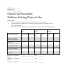
Check Out Procedure:
Problem Solving Project Labs
Points to Note:
•
Your instructor or GTA must sign this sheet before you leave each lab session.
•
You may not collect a signature late. For example, you may not collect a signature for Lab 1
when you come to Lab 2.
•
The penalty for missing signatures or a missing sheet is 20 points, which is 10% of the lab grade.
Item Description Qty.
Lab I
Lab II
Checked Out Checked In
Checked
Out
Lab III
Checked
In
1 Model Train Engine,
inside plastic container
1 USB cord,
unplugged and neatly wound
1 Track/Arduino board
1 12-volt DC Adapter,
unplugged and neatly wound
Clean Table
Lab I
Instructor/TA’s Signature:
Lab II
Instructor/TA’s Signature:
Lab III
Instructor/TA’s Signature:
_________________________ Date: ___________
_________________________ Date: ___________
_________________________ Date: ___________
Checked
Out
Checked
In