Transcript
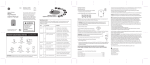
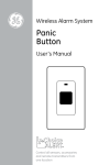
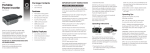
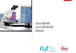
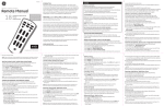
Enclosed you will find
• (1) Remote Light Switch
• Double-Sided Tape / Screws
(for mounting)
• (1) Indoor Plug-in Receiver
51138
02/10
Indoor Wireless
Light Switch
+
Any transmitter in the GE product line is
capable of controlling every receiver—the
ultimate in home convenience.
Control any number of light fixtures or
appliances from up to 150ft* away by
choosing the transmitter and receiver
combination that best suits your needs.
User’s Manual
WARNING
Risk of electric shock
• Keep children away
• Use indoors only
• Do not use in wet locations
Risk of fire
• Do not exceed electrical ratings
For technical support, call us at:
1-800-654-8483, option #4
Home Automation Series
+ +
Expanding your system
These devices operate on any of 8 user-settable channels. The channels are easy to set and
adjust with the simple turn of a knob. The following table is one example of how you can
configure your system:
Area
Bedside - Remote Light Switch
Entrance - Keychain Remote
(2) Bedside Lamps - (2) Socket Adapters
Corner Torchiere - Indoor Plug-in Receiver
Overhead Light Fixture - Remote Light Switch
Entertainment System - Indoor Plug-in Receiver
Living Room
2
Coffee Table - Remote Light Switch
(2) End Table Lamps - (2) Socket Adapters
Overhead Light Fixture - Remote Light Switch
Entertainment System - Indoor Plug-in Receiver
Christmas Tree - Indoor Plug-in Receiver
Entrance - Keychain Remote
3
Basement
Motion Sensor
& Plug-in Receiver
56765
ON
OFF
OFF ON
Outdoor Plug-in Receiver
51141
Socket Adapter
51142
4
Garage
Receivers
5
Outdoor
6
Wall Switch
51143
IMPORTANT! These devices are NOT compatible with devices from other systems.
You must purchase GE remotes and receivers to ensure compatibility.
Receivers
1
product line
ED!
INCLUD
Indoor Plug-in Receiver
51140
CH Remotes
Bedroom
ED!
Remote Light Switch
51147
+
+
+
Operate a lamp or
appliance by remote control.
INCLUD
Keychain Remote
51144
+ +
Window Santa - Indoor Plug-in Receiver
Lighted Poinsettia - Indoor Plug-in Receiver
Entrance - Keychain Remote
Remote Light Switch
Entrance - Keychain Remote
Remote Light Switch
(2) Fluorescent Fixtures - (2) Outdoor Indoor Plug-in
Overhead Light Fixture - Remote Light Switch
Foyer - Remote Light Switch
Car Keys - Keychain Remote
Entry Light - Remote Light Switch
Coach Lantern - Remote Light Switch
7
Kitchen
8
(4) Overhead Can Fixtures - (4) Socket Adapters
(2) Fluorescent Fixtures - (2) Indoor Plug-in Receivers
Christmas Lights - Outdoor Indoor Plug-in Receiver
Yard Santa - Outdoor Indoor Plug-in Receiver
Entrance - Remote Light Switch
Coffee Maker - Indoor Plug-in Receiver
is a trademark of the General Electric
Company and is used under license to
Jasco Products Company LLC,
10 E. Memorial Rd., Oklahoma City, OK 73114
www.jascoproducts.com
90 DAY LIMITED WARRANTY: Jasco Products
Company warrants this product to be free from
manufacturing defects for a period of 90 days
from the original date of consumer purchase.
This warranty is limited to the repair or
replacement of this product only and does not
extend to consequential or incidental damage to
other products that may be used with this unit.
This warranty is in lieu of all other warranties
express or implied. Some states do not allow
limitations on how long an implied warranty lasts
or permit the exclusion or limitation of incidental
or consequential damages, so the above
limitations may not apply to you. This warranty
gives you specific rights, and you may also have
other rights which vary from state to state. If unit
should prove defective within the warranty
period, return prepaid
with dated proof of purchase to:
Jasco Products Company
10 E. Memorial Rd.
Oklahoma City, OK 73114
Operating Instructions - Indoor Plug-in Receiver
B. Attach the double-sided tape to back of the Remote Light Switch housing.
C. Press tape firmly to the mounting surface.
FOR INDOOR USE ONLY
1. Remove the small tab on the back of unit labeled HOUSE CODE
using a small screwdriver.
2. Set the HOUSE CODE to any one of the following settings:
Screw Mounting
A. Using a slotted screwdriver, remove the faceplate of the Remote Light Switch.
B. Place the detached back plate where desired and mark screw locations.
C. Insert the mounting screws into the back plate holes and screw into place.
D. Replace the Remote Light Switch faceplate.
ON
1 2
5. Use the toggle button to activate the Remote Light Switch (ON/OFF operation). Make sure to press firmly
and for a minimum of 1 second for best results. An indicator lights RED when a signal is sent.
NOTE: Make sure ALL your GE devices have the same HOUSE CODE setting. The remotes WILL
NOT control the receivers if they have different HOUSE CODE settings.
6. Using any of the receivers set to the same CHANNEL and HOUSE CODE, test the installation by using the
ON and OFF buttons.
IMPORTANT! HOUSE CODES help eliminate interference (devices randomly turn on /off).
If you experience interference, change the HOUSE CODE on all your GE remotes and receivers to
a different setting.
3. Replace the HOUSE CODE tab.
4. Set the CHANNEL by using the knob on front as shown.
3
2
1
4
5
6
7
8
Battery Type ....................................................................................................... Use ONLY A23 (12V) Alkaline
NOTE: The functional range will decrease as the battery wears out so make sure to replace the battery
every 6 months for best results.
Specifications - Indoor Plug-in Receiver
NOTE: If you set your Indoor Outlet Adapter to CHANNEL 1,
the unit can be controlled using any remote set to CHANNEL 1. If you set your Indoor Plug-in Receiver to
CHANNEL 2, the unit can be controlled using any remote set to CHANNEL 2 … and so on.
IMPORTANT! A remote will control a receiver ONLY if they have the same
HOUSE CODE and CHANNEL settings.
FOR INDOOR USE ONLY - DO NOT EXCEED ELECTRICAL RATINGS
Electrical Rating ................................................................................................................................... 120V, 60Hz
Maximum Resistive Load ...................................................................................................................... 1200W
Maximum Tungsten Load ....................................................................................................................... 600W
Maximum Motor Load .............................................................................................................................. 1/3HP
*Functional range may be adversely affected by one or more of the following factors: weather, radio frequency
interference, low transmitter battery and obstructions between the transmitter and receiver.
5. Plug Indoor Outlet Adapter into a powered, grounded 125VAC outlet.
6. Plug the lamp / appliance you wish to control into the Indoor Plug-in Reveiver
as shown.
This device complies with Part 15 of the FCC rules. Operation is subject to the following two conditions:
1. This device may not cause harmful interference, and;
2. This device must accept any interference received, including interference that may cause undesired operation.
CAUTION: WHEN THE INDICATOR LIGHT IS ON, THE OUTPUT OUTLET IS POWERED.
DO NOT CONNECT / DISCONNECT DEVICES TO / FROM THE OUTLET ONCE
IT IS POWERED.
FCC Note: The manufacturer is not responsible for any radio or TV interference caused by unauthorized
modifications to this equipment. Such modifications could void the user’s authority to operate the equipment.
Operating Instructions - Remote Light Switch
1. Find the slot labeled HOUSE CODE on the back of the unit.
ON
1 2
2. Set the HOUSE CODE to any one of the following settings:
3. Set the CHANNEL by using the knob on front as shown.
NOTE: If you set your Remote Light Switch to CHANNEL 1, the unit can control
any receiver set to CHANNEL 1. If you set your Remote Light Switch to
CHANNEL 2, the unit can control any receiver set to CHANNEL 2 ... and so on.
Specifications - Remote Light Switch
3
2
1
4
5
6
7
8
4. Mounting
NOTE: Mounting the Remote Light Switch on masonry or metal walls may degrade the functional range.
Tape Mounting
A. Make sure surfaces are free of dust, oil and other substances that could affect adhesion.
NOTE: This equipment has been tested and found to comply with the limits for a Class B digital device, pursuant to
Part 15 of the FCC Rules. These limits are designed to provide reasonable protection against harmful interference
in a residential installation. This equipment generates, uses and can radiate radio frequency energy and, if not
installed and used in accordance with the instructions may cause harmful interference to radio communications.
However, there is no guarantee that interference will not occur in a particular installation. If this equipment does
cause harmful interference to radio or television reception, which can be determined by turning the equipment
off and on, the user is encouraged to try to correct the interference by one or more of the following measures:
- Reorient or relocate the receiving antenna.
- Increase the separation between the equipment and receiver.
- Connect the equipment into an outlet on a circuit different from that to which the receiver is connected.
Consult the dealer or an experienced radio/TV technician for help.
CAUTION: Changes or modifications not expressly approved by the party responsible for compliance could void
the user's authority to operate the equipment.