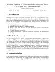
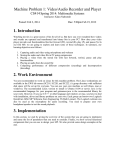
1
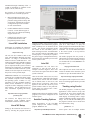
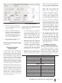
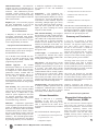
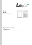
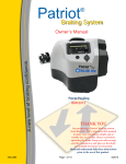
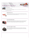
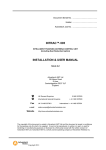
CNCTRK - A LinuxCNC Based Satellite Tracking System Bob Freeman, KI4SBL [email protected] T his paper presents a new approach to antenna positioner control and introduces a new Azimuth (AZ) and Elevation (EL) positioner designed for use in satellite tracking. The prototype positioning units have been integrated for use with the well known open source satellite tracking programs, Predict and GPredict, to enable tracking of LEO satellites. A complete ground station with tracking system, called CNCTRK, is shown in Figure 1. The block diagram shown in Figure 2 illustrates the simplicity of the CNCTRK system. The initial design intent of the overall system is to enable satellite tracking using small to medium sized (Arrow- and Elk-like) antennas. The system provides portable 12VDC operation and is camera tripod mountable. Figure 1 Complete Ground Station Using CNCTRK System This paper describes the prototype AZ/EL Antenna Positioning System (APS), the motion control approach, integration of the APS unit with tracking software, and touches on design considerations for the system. Prototype Hardware A custom, low-cost, gearbox has been designed for use in the new APS. The basis of the gearbox is a rigid CNC-machined aluminum housing. Starting with the housing, the assembly is built up using heavy duty ball bearings, worm gear drive, and 1/2” steel shafting. Stepper motors are used to drive the system as they are economical and provide simple, repeatable performance. Motor drivers are integrated into the system. Figure 2 CNCTRK System Block Diagram Motion Control Concept Motion control for CNCTRK is achieved without building a new rotor interface circuit. Instead, the motion planning and execution is provided via the open source LinuxCNC software (linuxcnc.org) running on the host computer (i.e. the same computer running Predict or GPredict). LinuxCNC is used worldwide for control of “big iron” computer numeric controlled (CNC) machinery in both professional and home shop environments. Modular Assembly There is only one gearbox design for the APS. In order to achieve dual axis operation, two gearbox units are ganged together with a 90 degree angular offset using a Configuration Adapter. For the initial prototypes, the axes are configured as an Elevation-over-Azimuth positioner as shown in Figure 3, on the right.. NOTE: Installation of the LinuxCNC system is a great way to re-purpose your old Windows machine! Figure 3 APS in EL-Over-AZ Configuration 2 The AMSAT Journal May/June 2015 www.amsat.org LinuxCNC (previously known as the Enhanced Machine Controller) was originally developed by National Institute of Standards and Technology (NIST). The program has been revised, enhanced, and maintained through community effort. A wealth of information is available on the project web site, linuxcnc.org. Key features of the LinuxCNC program employed for the CNCTRK project are: 1. Motion Planning and Control - the system provides soft start/stop of the positioner using profiled velocity and acceleration, simultaneous in all axes. Configuration options are available for user customization. 2. Flexible Machine Interface to Motor Controls - several different types of motor drives are supported, including steppers and servos. 3. Graphical User Interface (GUI) provides both interactive and programmed position control. LinuxCNC Installation Instructions for installing the LinuxCNC are available on the linuxcnc.org web site. http://linuxcnc.org/ The web site also contains a Wiki to aid users with installation. Basically, the latest linuxcnc .iso image is downloaded and burned to DVD or USB flash drive. The media is inserted into the candidate computer (for CNCTRK a computer with a parallel port is required) and the system is booted. Following the instructions for installation will result in a bootable LinuxCNC system. Thanks to the developers at linuxcnc.org, the process can be just that simple. Figure 4 LinuxCNC running AXIS GUI Applications Menu. Select a generic stepper configuration to start and have the program make a Desktop icon or Shortcut for the system. The specific information needed for control of the CNCTRK system is achieved using an .ini file. An initialization file is provided with the CNCTRK system for this purpose - it need only be copied to the generic stepper configuration directory and referenced by the desktop icon in order for the system to start. Axis GUI The initialization file will direct the LinuxCNC to start the Axis GUI; an example is shown in Figure 4, above. The Axis GUI is also required for the CNCTRK system to function. IMPORTANT NOTE: Live versions of the LinuxCNC are available that allow testing the candidate computer before installing the operating system. Further, it is very important to test the candidate machine’s latency before installation to verify the computer is able to adequately run the real time software. See the following site for more information regarding the latency test: Once the GUI has started, Press F1, Press F2, and Press the “Home All” button on the interface; these actions take the machine out of ESTOP, turns on the servos, and homes the axes, respectively. With power applied to the APS the cursor keys will provide manual control of the positioner. At this point you will now have a CNCbased antenna positioner! http://wiki.linuxcnc.org/cgi-bin/wiki. pl?Latency-Test. With the APS working, the satellite tracking program(s) can now be configured for use with the system. For reference, the laptop used in the development system exhibited latency measured at less than 25 micro-seconds. Satellite Tracking Options LinuxCNC Setup Initial development of the CNCTRK system employed the satellite tracking program, PREDICT. See: Setting up the LinuxCNC the first time is done by selecting the program from the http://www.qsl.net/kd2bd/predict.html This approach employs the use of a small piece of C code, cnctrk.c, to query the Predict program for Azimuth and Elevation values and then send these to the positioner controller. Use of CNCTRK with Predict is the easiest system to set up and less resource intensive. The Predict program does not provide a radio interface to enable computer control of the user’s radio; so, the CNCTRK concept was extended for use with GPREDICT for this purpose. See: http://gpredict.oz9aec.net/ This required a new rotator “back-end” be written for hamlib so the GPredict system could be set up in the normal fashion. See: http://sourceforge.net/projects/hamlib/ Descriptions of the setup and use of each of these two tracking approaches are provided as follows. Tracking using Predict The Predict program is a relatively small application, it is the easiest to set up, and is preferred for cases where manual radio control is used. Predict provides a text mode display for tracking either a Single satellite or Multiple satellites, among other things. For use with the CNCTRK system the program is started in server mode from the command line, using: predict -s Select option “M” for multiple satellite The AMSAT Journal May/June 2015 www.amsat.org 3 tracking display mode (highlighted entries are within view) or select option “T” to display tracking data for a single satellite. Once in track mode the predict server is available for use by client programs (such as the CNCTRK system). A screenshot of Predict in single satellite “T” mode is shown below, for reference. Similar as before, power the APS and start the LinuxCNC program (press F1, F2, Home All) and verify the system is operational via the cursor keys. A technique for aligning the system with earth coordinates is provided later. Open a terminal window and enter following command to initiate satellite tracking: cnctrk (A-Z designator for satellite) then press Enter The designator for the desired satellite, A to X, is found in PREDICT’s Track screen “T.” You may also enter a “Y” or “Z” to track the Sun or Moon, respectively. Once the designator (A to Z) is entered the APS will swing into position and the system will begin to track the target with position updates every second. The commanded Azimuth and Elevation values are displayed on the terminal as long as the unit is tracking. To stop the process, enter Ctrl-C in the same terminal window or tracking will also stop if Predict is removed from track mode using “q” or “ESC.” Tracking using GPredict Setup of GPredict is done in the normal fashion, as described in the GPredict documentation. Follow the instructions in the manual to setup radios, if needed. Gpredict employs the hamlib library for control of multiple radios and rotators. A new positioner (rotator) interface has been introduced for inclusion into hamlib for the CNCTRK system. The software is not yet included in the current release of hamlib so the sources must be compiled using the provided patch to the current release (presently, hamlib-1.2.15.3.tar.gz). Compiling Hamlib with CNCTRK Patch Download the current release of hamlib from the above web site then unpack using tar xzf hamlib-1.2.15.3.tar.gz Copy the provided patch file to the hamlib 4 Figure 5 PREDICT in single satellite mode directory, change to the directory, and apply the patch using: patch -p1 patch < hamlib-1.2.15.3_cnctrk. Compile the sources as usual using ./config make sudo make install To get started, power the APS and start the LinuxCNC program (press F1, F2, Home All) and verify the system is operational via the cursor keys. To verify the APS interface is working through hamlib use the function “rotctl” to start an interactive session. From the command line, proceed as follows: rotctl -m 1501 (the hamlib model number for the APS is 1501) P (enter Azimuth and Elevation data desired) When finished, press Ctrl-C to stop the rotctl interactive program. In order to use the APS with GPredict the rotctl program must be run in the operating system as a daemon; open a terminal and use the following command to run the daemon process in the background: rotctld -m 1501 & The AMSAT Journal May/June 2015 www.amsat.org At this point the LinuxCNC and hamlib processes are ready to accept position commands from the tracking software. GPredict Setup Again, setup of GPredict is done in the normal fashion. Follow the instructions in the GPredict manual to setup the rotator and position limits under the Edit>>Prefe rences>>Interfaces>>Rotators pull-down menu. Select either “Add” or “Edit,” as needed to configure the parameters. For more information see the user manual at: http://sourceforge.net/projects/gpredict/files/ Gpredict/1.3/gpredict-user-manual-1.3.pdf/ download Open the “Antenna Control” from the pull-down menu (small icon located at the top right of the main GPredict screen). Initiate control of the APS by clicking on the “Engage” button. The APS can also be manually jogged using the up/down arrows on the numerical position display. The “Track” and “Engage” buttons will remove manual control and place the APS under control of the GPredict program, as needed for satellite tracking. A screenshot of of the Antenna Control window during active tracking of satellite AO-27 is shown in Figure 6. Field Alignment of Coordinate System To align the system in the field a tripod mount and sunny day is assumed. Start the LinuxCNC program, the tracking program Predict, and proceed as follows: characteristics for torque, voltage, and current. A NEMA-23 standard motor size is used in the CNCTRK system. NOTE: The first prototype unit used stepper motors from old printers with excellent results. It should be noted that the LinuxCNC is capable of controlling a wide range of motor controls, including servos; see the linuxcnc.org Wiki for a list of known working motor interfaces. Figure 6. GPredict Antenna Control During Tracking of AO-27 1. Level the Azimuth axis Cost Considerations 2. Initiate Sun tracking in Predict (this steers the Azimuth and Elevation axes to the correct angle) Several factors were considered in the APS design to reduce cost of the units; some of these are listed below. 3. Unlock the tripod mount and rotate about the vertical axis until the Sun is in alignment with the antenna beam. Once aligned, a dual band antenna will produce a shadow that resembles an “X” or cross on the ground. 1. To take advantage of the economies of scale, the positioner employs a modular design and parts reuse. The gearbox design, including the drive system, is re-used for each axis in the system. Connecting parts are used in multiple applications, where possible. 4. The system is now aligned; lock the tripod vertical axis in place. If the Sun is obscured then use of a compass or other means may be employed to align the Azimuth axis. Prototype Hardware Characteristics As mentioned previously, a custom gearbox is made from a rigid CNC machined aluminum housing, heavy duty ball bearings, worm gear drive, and 1/2” steel shafting used throughout. Stepper motors and generic motor drivers accepting Step and Direction signals from the LinuxCNC computer provide the drive for the system. Finally, the range of Azimuth axis rotation is made greater than 360 degrees through the use of a wrapped power/control cable. Mechanical and electrical characteristics of the prototype system have been measured. The drive settings for the motor drivers were set to conservative values. The rotation velocity is a function of the computer used with the system; the values listed are for reference only. A summary of measured characteristics data from one of the prototype units is provided in Table 1. 2. Worm gears used in the system are commodity gear kits; they will provide long service life and are inexpensive to replace. The position accuracy achieved using the worm drive system is entirely sufficient for Amateur satellite operation where antenna 3dB beamwidths are in excess of 20 degrees. 3. Stepper motors are used to drive the assembly. These are widely available and can be purchased with a range of 4. The free, open source, LinuxCNC program provides the motion control logic for the CNCTRK system. This is a flexible and stable real time platform with proven performance. Use of LinuxCNC reduces tracking system cost by eliminating the need for a separate “track box” assembly and associated cabling or other proprietary interface to commercial antenna rotators. 5. The CNCTRK system, shown in the previous block diagram, employs only three major components, 1) a laptop or other computer with printer port and cable, 2) a DC power supply, and 3) the APS. Power for the APS may be provided from any available DC source in the range of 12 to 24 VDC, including battery power. Flexibility and Future Enhancement Opportunities The CNCTRK system provides a suitable platform for its intended purpose of tracking amateur radio satellites. Enhancements to the system are always possible, as are alternative uses for the system. Some ideas along these lines include: Azimuth or Elevation Axis Holding Torque 48 in-oz Velocity 15 deg/s default setting Backlash 2 deg Theoretical Resolution 0.007 deg at 1/16 microstep APS Assembly Weight 8.5 lb Finish Bare Aluminum Azimuth Range -90 deg < AZ < 450 deg Elevation Range -20 deg < EL < 90 deg Position Accuracy +/- 2 deg Dimensions Approx. 7x 7 x 8 inches Power Consumption (Idle) 0.25A x 12VDC = 3 Watts Power Consumption (AZ/EL Steering) 2.00A x 12VDC = 24 Watts (default) Table 1 System Characteristics The AMSAT Journal May/June 2015 www.amsat.org 5 Home/Limit Switches - The LinuxCNC program can easily accommodate the use of limit switches wired to the 25-pin I/O connector. This enhancement provides repeatable position location from one session to the next. The aluminum housing provides ample area for addition of this and other custom features. Raspberry Pi - The LinuxCNC program has been demonstrated to run on the Raspberry Pi (RPi); for an example see: http://www.youtube.com/ watch?v=Kz02FxYAvC4 A Raspberry Pi based system has been successfully implemented using Predict. An additional circuit board is employed to generate step pulses; the PCB is an open source design and may be found at: http://github.com/kinsamanka/PICnc-V2 The PRi solution requires much less power than the laptop system and no changes to the APS hardware are needed. Use of the RPi with CNCTRK may also serve as an avenue of interest for young operators that are already familiar with programming the platform. Modular Approach - The modular characteristic enables two or more axes to be assembled, as needed. These units may be configured as a mast mounted system, polarization rotators, azimuth table for antenna range measurements, and so on. Or, how about a Roll-Over-ElevationOver-Azimuth configuration for AZ, EL, and Polarization control? The LinuxCNC will control at least four axes using a single parallel port. Solar Tracking - The system can be made to track the Sun. This is already enabled when using the Predict program interface, cnctrk.c, and is a feature that is quite useful for system alignment in the field. An alternate application might include positioning of photo-voltaic (solar) panels for maximum energy collection. Education - Educational opportunities exist through the exploration and use of this project. In addition to the diverse offerings that come with amateur radio and satellite communications, there is much to learn in the area of mechanical systems, motor and motion control, and the concepts of CNC machinery. The CNCTRK ground station approach may be beneficial to the student by providing relatively low cost hardware 6 to enable the exploration of the concepts and practices of CNC and mechanical systems. Performance - The mechanical performance of the basic gearbox may be improved through the addition of a custom worm gear set. A gear set with finer pitch could achieve lower backlash, improved self-braking (through higher gear ratios), and overall improved position accuracy. Note that slower speeds will result with higher gear ratios, assuming the control computer is held constant. Dual Antenna Mounting - The length of the Elevation axis shaft is made purposely long and extends on both sides of the APS. This enables one to adapt shaft extensions on the APS unit to provide separation distance between antennas that may be mounted on both sides of the APS. For example, one might mount a 2m crossed Yagi-Uda on one side and a 70 cm beam on the opposite side. Counterweight - A counterbalance may be employed for antennas that require greater torque than is readily available with existing motors and gearing. More Power! - The motor driver circuits employed in the prototype system were adjusted to approximately 1.0 A per driver at 12 VDC. The motor driver circuits provided with the system are based on the Toshiba TB6600 and are actually capable of driving up to 4.5 A at 24 VDC. While use of the drivers at these levels has not been tested by the author, it does offer the potential for much greater delivered torque from the APS with the existing motors. Weatherproofing - The initial APS design is meant for portable operation and is not weatherproof. Additional parts or features could be added to the unit to increase survivability in the outdoor environment. Kits and Assemblies Supply of APS kits is a possibility, depending on the level of interest. Mechanical assembly and wiring of the APS is required but the motor driver electronics are furnished as fully assembled modules. Kits would include the following items: • CNC Aluminum parts and components for two gearboxes (AZ + EL) • Configuration Adapter The AMSAT Journal May/June 2015 www.amsat.org • Stepper motors and drivers • Assembly instructions in electronic form • CDROM or DVD with Linux-CNC distribution • CDROM or Flash Drive with setup file and cnctrk.c Note that since custom machined parts are used, there may be significant lead times for the APS kit components. All RF equipment and cables needed to complete a ground station are to be provided by the user. Summary and Conclusion A new low cost approach to antenna positioning for satellite tracking has been described. The approach employs existing open source motion control software in the form of the LinuxCNC to handle the hardware layer mechanical control. A new APS has been designed, built, and tested. Further, the prototype units are integrated with open source satellite tracking programs, thus enabling tracking of LEO satellites. The design intent of the system is to enable satellite tracking using small to medium (Arrow and Elk) sized antennas. The system provides portable DC powered operation and, weighing about eight (8.5) pounds, is suitable for use on a (sturdy) camera tripod. This article has described the CNCTRK system, the prototype APS, integration of the unit with available tracking software, and has touched on the design approach and possible enhancements of the system. Questions, suggestions, and inquiries regarding the CNCTRK system are welcomed by the author. Additional information may be found at: http://ki4sbl.dodropin.org/CNCTRK/ Biographical information for Bob Freeman, KI4SBL Bob is a career microwave antenna engineer with several years experience in antenna design and measurement. Interests include microwave engineering, amateur radio, hobby CNC, RVing, tree climbing and other outdoor activities. Bob and wife Cathy, KI4SBK, currently reside in Cumming, GA or somewhere along a scenic highway in the USA.