1
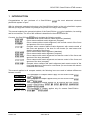
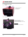
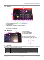
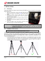
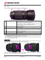
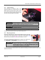
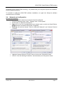
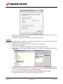
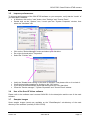
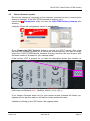
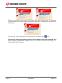
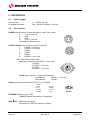
SCAN'O'VISION STAR CAMERA OSV-STAR User’s Manual 3434.505.02 Version 2.0 Edition November 2012 Caution and safety precautions Never use any other charger than the supplied or a type approved by Swiss Timing. This could destroy the battery, cause damage to unit, and possible cause personal injury due to fire or/and electrical shock. Never bypass a power cord ground lead by breaking off the ground pin, or by using inappropriate extension cords or adapters. Never plug a power cord into the AC power source until you have made sure that all installation, cabling and power levels, are proper, and that the applicable procedures in this manual have been followed. Protect the equipment against splashing, rain and excessive sun rays. Never use the device if it is damaged or insecure. Verify the selection of the power distribution. Verify that the voltage quoted on the rating plate is the same as your voltage. Connect the appliance only to power sockets with protective earth. The use of incorrect connection voids warranty. This program may be modified at any time without prior notification. Do not open the case; there is nothing that needs servicing inside it. Nevertheless, if the case must be opened, you must call for some qualified personnel. The power supply cable must be disconnected before opening the case. During the transport of all Swiss Timing equipment delivered with a reusable carry case, the said case should be used at all times. This is imperative to limit the damage, such as shocks or vibration that can be caused to the units during transport. The same cases should also be used when returning equipment to Swiss Timing for repair. Swiss Timing reserves the right to refuse all guarantees if this condition is not fulfilled. If the installation includes a horn, be sure to maintain a sufficient security distance from the public. Documentation Updates Swiss Timing Ltd. reserves the right to make improvements in the products described in this documentation at any time without prior notice. Furthermore, Swiss Timing Ltd. reserves the right to revise this documentation in its content at any time and without any obligation to notify any person or organization of such revision. Disclaimer The information provided in this documentation has been obtained from sources believed to be reliable, accurate and current. However, Swiss Timing Ltd. makes no representation or warranty, express or implied, with respect, but not limited to, the completeness, accuracy, correctness and actuality of the content of this documentation. Swiss Timing Ltd. specifically disclaims any implied warranty of merchantability, quality and/or fitness for any particular purpose. Swiss Timing Ltd. shall not be liable for errors contained in this documentation or for incidental or consequential damages in connection with the supply, performance or use of this documentation. Environment This symbol indicates that this product should not be disposed with household waste. It has to be returned to a local authorized collection system. By following this procedure you will contribute to the protection of the environment and human health. The recycling of the materials will help to conserve natural resources. Copyright © Swiss Timing Ltd. All rights reserved. This documentation may not, as a whole or in part, be copied, translated, reproduced, transmitted or reduced and/or stored to any electronic medium or machine-readable form without the prior written consent of Swiss Timing Ltd. OSV-STAR / Scan'O'Vision STAR camera TABLE OF CONTENTS 1 INTRODUCTION........................................................................................................... 1 1.1 1.2 2 3 4 Presentation of the camera ............................................................................................... 2 1.1.1 Top view ............................................................................................................. 2 1.1.2 Front view ........................................................................................................... 2 1.1.3 Rear face ............................................................................................................ 3 1.1.4 Bottom view ........................................................................................................ 3 Definitions.......................................................................................................................... 3 INSTALLATION ............................................................................................................ 4 2.1 First setup .......................................................................................................................... 4 2.2 Installation of the camera .................................................................................................. 4 2.3 Choice of the lens ............................................................................................................. 5 2.4 Lens ................................................................................................................................... 6 2.5 Lens mounting ................................................................................................................... 7 2.6 Removing the lens ............................................................................................................ 7 2.7 Wiring the installation ........................................................................................................ 8 2.8 Power on and power off .................................................................................................... 8 2.9 Loading of the internal battery .......................................................................................... 8 2.10 Indicators ........................................................................................................................... 9 SOFTWARE ............................................................................................................... 10 3.1 Computer......................................................................................................................... 10 3.2 Screen saver ................................................................................................................... 10 3.3 Software installation ........................................................................................................ 10 3.4 Network card configuration ............................................................................................. 11 3.5 Improve performances .................................................................................................... 13 3.6 Use of the Scan'O'Vision software.................................................................................. 13 3.7 Samples images.............................................................................................................. 13 3.8 Update ............................................................................................................................. 14 3.9 Camera firmware update ................................................................................................ 15 OPTIONS .................................................................................................................... 17 4.1 Internal battery ................................................................................................................ 17 SWISS TIMING LTD SWISS TIMING LTD P.O. Box 138, rue de l'Envers 1 2606 Corgémont, Switzerland www.swisstiming.com Phone +41 32 488 36 11 Fax +41 32 488 36 09 [email protected] 5 6 7 4.2 GPS ................................................................................................................................. 17 4.3 Optic fibre connection ..................................................................................................... 17 4.4 WiFi ................................................................................................................................. 17 4.5 Working on external battery ............................................................................................ 17 PROPERTIES ............................................................................................................. 18 5.1 Power supply ................................................................................................................... 18 5.2 Connections .................................................................................................................... 18 5.3 Technical characteristics................................................................................................. 19 MAINTENANCE AND PROTECTION ........................................................................ 20 6.1 Storage ............................................................................................................................ 20 6.2 Maintenance .................................................................................................................... 20 6.3 Camera reset................................................................................................................... 20 APPENDIX .................................................................................................................. 21 7.1 Abbreviations and symbols ............................................................................................. 21 7.2 Index of tables and figures .............................................................................................. 21 7.3 Version history................................................................................................................. 21 SWISS TIMING LTD SWISS TIMING LTD P.O. Box 138, rue de l'Envers 1 2606 Corgémont, Switzerland www.swisstiming.com Phone +41 32 488 36 11 Fax +41 32 488 36 09 [email protected] OSV-STAR / Scan'O'Vision STAR camera 1 INTRODUCTION Congratulations on your purchase of a Scan'O'Vision photofinish system in sport. , the most advanced electronic With its advanced, patented technology, the Scan'O'Vision family is the only photofinish system that lets you align the camera very easily on any finish line using a video image. This manual explains the general principles of the Scan'O'Vision , its installation, its working and its connections. The use of the software is described in the manual 3434.501. Currently, the Scan'O'Vision family includes the following models: : Black and white camera without matrix alignment (standard). : Colour camera without matrix alignment (compact). : Colour camera without matrix alignment, with remote control of the focus and aperture of the lens (compact). : Compact colour camera without matrix alignment, with remote control of the focus and aperture of the lens for new lenses (for new lenses with electric command of the focus). : Colour camera with matrix alignment (standard). : Colour camera with matrix alignment (compact). : Colour camera with matrix alignment and remote control of the focus and aperture of the lens (standard). : Colour camera with matrix alignment and remote control of the focus and aperture of the lens (compact). : Compact colour camera with matrix alignment and remote control of the focus and aperture of the lens for new lenses (for new lenses with electric command of the focus). This manual applies to all compact models; the following icons are used to indicate differences between models: This paragraph or chapter doesn't apply for the Scan'O'Vision nor . This paragraph or chapter applies solely for the Scan'O'Vision and . This paragraph or chapter applies for all camera with lens remote control (Scan'O'Vision , , , and ). This paragraph or chapter applies only for camera Scan'O'Vision and . Version 2.0 3434.505.02 Page 1 1.1 1.1.1 Presentation of the camera Top view 1. Handle to carry the camera. 2. Initial alignment sight. 3. Axis of alignment. 1.1.2 Front view 10. Fixing for lens protection. 11. Reference mark (hole) for lens mounting. 12. Latch for unlocking the lens. 13. Nikon mount for lens fixing (with protective cap). 14. Clutch button of the remote control lens. Page 2 3434.505.02 Version 2.0 OSV-STAR / Scan'O'Vision STAR camera 1.1.3 Rear face 20. Yellow LED: indicators for vertical status [see 2.10]. 21. Green LED: indicator of working status (lit when the camera is in operation). 22. Air output with ventilator. 23. Connection for WIFI antennas (WIFI Option) [see 2.7 and 4.4]. 24. Power supply input. 25. Ethernet Gigabit connection for computer link [see 2.10]. 26. Serial line [see 5.2]. 27. Connection for GPS antenna (GPS Option) [see 2.7 and 4.1]. 28. RESET button [see 6.3]. 29. Input for start and finish signals. 1.1.4 Bottom view 30. Air entry with filter. 31. Fixing screws for air filter. 32. Cover for battery access. 33. Screw for opening battery cover. 34. Descriptive sticker with model and serial number. 35. Fixing for photo support UNC 3/8". 36. Other fixing points (4 x M6, depth 16mm). 1.2 Definitions The camera is typically supplied with a support permitting the setting of its position according to 4 axes, here are the definitions used in this manual: Translation Horizontal displacement, perpendicular to the finish line. Pan Rotation in the horizontal plane. Tilt Rotation in the vertical plane, in the axis of the finish line. Swivel Rotation in the vertical plane, perpendicular to the finish line (to have the sensor "vertical" in the plane of the finish line). Version 2.0 3434.505.02 Page 3 2 INSTALLATION 2.1 First setup If you have ordered the optional internal battery [3434.980], you have to mount it in the camera before the first use: 1. With the delivered tool, remove the screw that block the battery cover (point 33 of chapter 1.1.4) and open battery cover. 2. Inside the camera, find the cable with the connector corresponding to the battery pack, and pull it (gently) a little bit out of the camera. 3. Enter the battery pack in the location (with the wires on the external). 4. Connect the connectors together and then insert totally the battery. 5. Close the battery cover and block it with the screw removed on point 1 using the delivered tool. Remarks : 2.2 The battery is delivered uncharged. Use only the delivered battery. Use of other kind of battery can seriously damage the camera due to the charger type; in this case the camera guarantee will be loosed. Installation of the camera The photofinish camera must be installed exactly on a virtual extension of the finish line and the sensor must be vertically perpendicular to this line. The inclination of the camera is important for the ease of judgment. In general, a vertical inclination of 8o to 10o is used for the rowing and the canoeing, and of 10o to 20o (in relation to the middle of the finish line) for the cycling, the horse-racings and of greyhound. For athletics, an angle of 25o to 30o is recommended in relation to the farthest lane in order to prevent the competitors in the foreground masking another. Centre the tripod on the extension of the finish line. If it is equipped with a spirit level, align the bubble precisely in the middle of the reference mark. Then slowly tighten all screws checking bubble does not move. For a better stability, spread the legs as far apart as possible and do not raise the central extension tube: Page 4 3434.505.02 Version 2.0 OSV-STAR / Scan'O'Vision STAR camera Fix the upper part of the support camera solidly below the camera. On the tripod, first to fix the slide permitting the translation then the support permitting the three way rotation. If required, move the tripod so that the translation movement can be made perpendicularly (horizontally) to the finish line. Fix the camera on the support (quick lock). Thereafter, to remove the camera, it is sufficient to disassemble this quick lock while using the handle and the security button. For more of details, please refer to the manual for the support. 2.3 Choice of the lens The choice of the lens is very important, only the lens with a NIKON bayonet can be used. The NIKON AF lenses are recommended (compatibility with option of motorization). New lenses have no more aperture ring and focus is controlled electrically instead of mechanically (in addition to the manual focus ring), these lenses can only be used on STAR models 220 and 2020. Please check with a Swiss Timing representative before purchasing a Nikon compatible lens as several models are not compatible with the STAR’s highest resolutions. Swiss Timing can also provide you the lens corresponding exactly to your camera model. NEW Lens control Replaced by 3434.936 Camera No. 3434.724 3434.734 3434.722 3434.723 3434.732 3434.733 STAR STAR STAR STAR STAR STAR 220 20/20 110 210 1010 2010 Lens Item no. and description MOT MOT MAN MOT MAN MOT MAN MOT MAN Focus Focus Aperture Model Focus 3434.935 Aperture 3434.934 Aperture 3434.923 Focus 3434.922 Aperture 3434.936 Aperture 3434.926 Focus Sales No. Aperture Manual Motorized Not compatible Focus MAN MOT Replaced by 3434.926 MOT Zoom lens 24-70mm f/2.8-4 (Nikon-mount) MOT Zoom lens 70-300mm f/4-5.6 (Nikon-mount) MOT 9051.6252 Zoom lens 24-70mm f/2.8-4 (Nikon-mount) MOT MAN MOT MAN MAN MOT MAN MOT 9051.6253 Zoom lens 70-300mm f/4-5.6 (Nikon-mount) MOT MAN MOT MAN MAN MOT MAN MOT 9051.6254 Zoom lens 170-500mm f/5-6.3 (Nikon-mount) MOT MAN MOT MAN MAN MOT MAN MOT NEW 9051.6255 9051.6256 MOT and MAN MOT MOT MOT and and MAN MAN and MAN The choice of the correct focal distance is important to frame the finish line correctly. The "OSVFOCAL.XLS" file (on the CD-ROM or in the application directory) will calculate the focal distance required based on inputted values. Please check all values carefully. Microsoft EXCEL software (not included) is required to use this file. To have top-quality pictures, we recommend to use lenses with a very big aperture (small number of diaphragm), especially in conditions of weak light. Version 2.0 3434.505.02 Page 5 2.4 Lens The lens is composed of different parts, the interesting parts are: A* Aperture ring B Zoom ring C Focus ring D Hood E* Aperture lock To set the lens aperture (or opening). The higher the number is, darker the image will be, but the sharpness between near and far objects will be improved. The smaller the number is, lighter the image will be, but the sharpness between near and far object will decrease. On new lenses, this ring do not exists any more; so the lens remote control is mandatory. To choose the focal length of the lens. This ring does not exist on fixed focal lenses. To adjust the sharpness (or focus). Must be set in relation to the distance between the lens and the middle of the track; the final setting must be done when viewing the image on the computer (OSV-STAR software in setting mode). Removable mechanical part. Must be mounted to protect the lens from sun and rain. In the locked position, the aperture cannot be adjusted manually. * For camera with lens remote control, set the aperture ring [A] to the highest number and move the aperture lock [E] to stop the aperture ring turning. For camera without lens remote control, verify the aperture ring [A] can be manually turned; if not, move the aperture lock [E]. To be able to control the focus by software, the lens must be on the AF mode; this is done differently according to the lens (small switch or focus ring sliding). F If the focus is manually changed on the lens in AF mode, the mode must be set on M and then again on AF in order to allow software focus remote control. Page 6 3434.505.02 Version 2.0 OSV-STAR / Scan'O'Vision STAR camera 2.5 Lens mounting After removing the protective caps of the camera and the lens, to insert the lens in the Nikon mount (to put the dot of colour of the lens in front of the dot of the ring [1]) and to turn the lens counter clockwise until you hear the click of the lock (about 1/6 turn) [2]. Before fixing the lens on the camera, always set the minimum aperture (biggest number possible) and only change it with the software remote control (the ring does not move). Press the clutch button (point 14 of chapter 1.1.1) during the mounting of the lens. Never touch the glass of the camera or lenses with your fingers. If a hood is delivered with the lens you should always use it. 2.6 Removing the lens Before the dismounting the camera, it is necessary to remove the lens. To do this, hold the lens in the left hand; with a finger of your right hand, push on the unlocking latch [1] (see point 12 of chapter 1.1.1) and turn the lens clockwise [2] until it is free (about 1/6 turn). 2 1 With and cameras, a plastic tool is delivered to help the push on the unlocking latch when big lenses are used. Press the clutch button (point 14 of chapter 1.1.1) during the removal of the lens. If the clutch button can not be fully pressed, do not force; it is generally sufficient to give one or two command of focus in the software OSV-STAR (camera setting mode) to unblock the mechanism In order to protect the camera and the lens, please immediately put back the protective caps of the camera and the lens. Version 2.0 3434.505.02 Page 7 2.7 Wiring the installation Connect the delivered Start-Finish cable (3434.620) at the rear of the camera on the START/FINISH connector (29). Connect the start transducer on the TUCHEL Start plug of this cable and the finish cell on the FINISH bananas of this cable. If you want to do manual recording of images, it is recommended to connect a pushbutton (option 2872.003) on the FINISH bananas. Connect the network cable Ethernet Gigabit (9051.1315) between the ETHERNET connector on the camera (25) and the computer. If the GPS option is present and will be used, connect the antenna on the GPS connector on the back of the camera (see also point 27 of chapter 1.1.3). Push the plug of the cable until it clicks into place to connect the antenna. Pull the plug of the antenna cable by the front part (F) to disconnect the antenna. Connect the provided AC/DC power adapter to mains power and the POWER connector on the camera (24). The camera will automatically start up (see chapter 2.8). An external battery 12VDC can be used instead the AC/DC power adaptor when no mains power is available at the site of the camera (option battery cable 3330.618). 2.8 Power on and power off When the power cable is plugged, the camera starts itself. The green LED on the rear face should be lit. The green LED of the AC/DC adaptor should also be lit. At power on, the camera initializes itself during about 80 seconds, then, at least one of the two yellow LED (vertical indicators) blinks; the camera can now be aligned and is ready for use. To power off the camera, it is necessary to first exit the Scan'O'Vision computer, and then remove the power cable. When you power off the camera, the synchronization is lost. software on the With the optional internal battery, if the power is removed while the software is running, the internal battery will automatically keep the camera on until the reserve power is depleted or you exit the OSV-STAR software (in this case a question is asked if one wants or no to switch off the camera from the software). 2.9 Loading of the internal battery As soon as the camera is powered on (green LED lit), the optional internal battery starts charging if necessary. It takes up to 9 hours to completely charge the internal battery. Page 8 3434.505.02 Version 2.0 OSV-STAR / Scan'O'Vision STAR camera 2.10 Indicators On the rear panel, different LEDs indicate the state of the camera: State of LED Status Camera switched off. Camera switched on, in phase of initialization. Camera switched on and ready, perfectly vertical sensor. Camera switched on, non vertical sensor. Seen from rear, the right side of the camera is too high. Camera switched on, non vertical sensor. Seen from rear, the left side of the camera is too high. Indicates that the LED blinks. The faster the LED blinks, the closer the sensor is to vertical. ETHERNET: In the connector, the left LED indicates: Off Green Orange No connection. Connection at 100Mbps. Connection at 1Gbps [normal state of use]. The right LED blinks when there is a transmission of data in progress. On the AC/DC power adapter, a green LED should be lit if the plug is connected to a mains power outlet (115/230VAC). Version 2.0 3434.505.02 Page 9 3 SOFTWARE 3.1 Computer The Scan'O'Vision minimum specifications: Screen resolution: camera works with a computer (laptop or desktop), with the following RAM (memory): CPU (Processor): Hard disk: Extension slots: Network: Operating system: Data storage: Various: Minimum 1280x1024. 1920x1200 recommended Minimum 1GB for one camera. 2GB recommended compatible with Intel (Pentium M / Celeron) or AMD processors, minimum 1,5GHz Minimum 40GB Recommended: 1 x PCI (desktop) or 1 x PCMCIA (laptop) for 2nd network. 2 separate networks: 1 Gigabit Ethernet port for camera use only *. Common 10/100 Ethernet port (or better) for connection to DH and judging computers (optional). ‘IP over Firewire’ can also be used if two computers have IEEE1394 connections. Windows XP Home or Professional edition (recommended), Windows VISTA, Windows 7. DVD writer recommended. CD-ROM reader (for software installation) RS232 serial port recommended. * : a PCI card or PCMCIA can be added (for example for a laptop, the card NETGEAR Gigabit PC Card GA511). 3.2 Screen saver Please deactivate any screen savers while the system Scan'O'Vision use. is in If the computer enters the screen saver, sleep or hibernation mode while the software is running, the connection to the camera could be lost. The connection is automatically re-established when exiting these modes; but if you were in acquisition mode or setting mode the software is automatically redirected to the race mode. 3.3 Software installation Before the first use of the Scan'O'Vision computers hard disk. system, the software must be copied to the Insert the provided CD-ROM in the computer's reader, the installation software must run automatically after a moment; if not, please run the Setup.exe software from the CD-ROM. It is recommended to use the "Typical" installation. The main software is started by double clicking on the shortcut created on your desktop or by double clicking on the "OSV7.EXE" file in the main folder of the installation (C:\OSV-STAR). If errors occur when launching the OSV-STAR software, please refer to the ReadMe.txt file Page 10 3434.505.02 Version 2.0 OSV-STAR / Scan'O'Vision STAR camera (contained in the C:\OSV-STAR directory); it is possible that your computer require the installation of some additional libraries. To uninstall or modify the OSV-STAR software installation, run again the Setup.exe software contained on the CD-ROM. 3.4 Network card configuration a) Protocol & address The network card to which the camera is connected must be configured: Press the windows button "Start", "Settings" then "Control panel". Double click on "Network Connections". Right click on the line corresponding to the network card on which the Scan'O'Vision camera is connected and choose "Properties". Deactivate all services except "Client for Microsoft Networks" and "Internet Protocol (TCP/IP)". Version 2.0 Highlight "Internet Protocol (TCP/IP)" then to click on the "Properties" button. Click on "Use the following IP address:" and enter data, as in the picture below: 3434.505.02 Page 11 Click on the "OK" button of this window, and then on the "OK" button of the previous “Connection Properties” window. The system may ask you to restart the computer at this point. b) Speed To ensure a constant data transfer, it is highly recommended to fix the transmission speed between the camera and the computer to 1Gb: Press the windows button "Start", "Settings" then "Control panel". Double click on "System ". Click on the "Hardware" tab and then on the "Device Manager" button. Right click on the network adapter where the camera is connected and select "Properties". Page 12 Select the "Advanced" tab; select "Link Speed/Duplex Mode" in the list and change the value from "Auto Negotiation" to "1000Mbps/Full Duplex". Note: the previous text in magenta may change depending of the network adapter. Close all the opened windows by clicking on the corresponding "OK" button. The system may ask you to restart the computer at this point. 3434.505.02 Version 2.0 OSV-STAR / Scan'O'Vision STAR camera 3.5 Improve performances To improve performances of the OSV-STAR software on your computer, verify that the "cache" of your hard disk is enabled: In Windows, click on the "start" button, then "Settings" and "Control Panel". Double click on the "System" icon, it must open the "System Properties" window, then select the "Hardware" tab. 3.6 Click on the "Device Manager" button and select your disk drive. Do a right click and select "Properties". Select the "Policies" tab. Verify the "Enable write caching on the disk" is checked. If not please click on it to check it. Close the hard disk properties by clicking on the "OK" button. If you have several hard disks, repeat the latest points for every hard disk. Close the "Device manager", "System Properties" and "Control Panel" window. Use of the Scan'O'Vision software Please refer to the software user's manual 3434.501 for the description and the use of the main software. 3.7 Samples images Some sample images (races) are available on the "\Data\Samples" sub-directory of the main directory of the software (normally C:\OSV-STAR). Version 2.0 3434.505.02 Page 13 3.8 Update The software updates are available as free download on our web site: www.swisstiming.com In some cases, the firmware of the camera must also be updated (see chapter 3.9). In any case it must be current with the version of the main software; if this is not the case, a warning message will be displayed when you launch the Scan'O'Vision application: “Incompatible hardware/software version”. Page 14 3434.505.02 Version 2.0 OSV-STAR / Scan'O'Vision STAR camera 3.9 Camera firmware update Be sure the camera is connected to the computer, powered on and is running (boot sequence finished). If the OSV-STAR software is running, exit it. Launch the Firmware.exe utility tool from the OSV-STAR\Camera_firmware subdirectory. Verify the “Erase old configuration values” is not checked. Press “Update the OSV7 Camera” button to connect your OSV7 camera. After a few seconds, the software prompts you to select the archive directory you want to install, select the C:\OSV-STAR\Camera_firmware directory and then the sub-directory with the latest version of firmware for your camera model: If the number “555” is present on (or near) the descriptive sticker (see location on chapter 1.1.4), you should use firmware OSV_STAR_CAMERA_MODEL_v_..., in other case use firmware OSV7_CAMERA_MODEL_x10_&_x20_v_... If you chose a firmware which isn’t for your camera model, software will inform you, upgrade will not be done and you will have to chose another firmware. Validate by clicking on the "OK" button, the upgrade starts. Version 2.0 3434.505.02 Page 15 The blue process bar must reach 100% then, after about 20 seconds, the message “Please restart OSV-STAR camera and exit this software” is displayed in the bottom of the window. You can now exit the Firmware.exe utility tools by clicking on the icon. You have to unplug the power connector of the camera, wait some seconds, and plug it again to restart the camera. Once the camera has finished rebooting, you can start the OSV7 software. Page 16 3434.505.02 Version 2.0 OSV-STAR / Scan'O'Vision STAR camera 4 OPTIONS 4.1 Internal battery A battery (option 3434.980) can be installed inside the camera. This battery allows the camera to continue to work up to one hour in case of power failure; so it is a good way to use with a laptop without need of UPS. Please refer to chapter 2.1 to mount this battery in the camera. When the camera is working on his internal battery and the battery is low, a “bip” sound is emitted by the camera and the OSV7.exe software; when the battery is very low, the camera is automatically switched off. 4.2 GPS The GPS receiver option (Global Positioning System) allows a very precise synchronization of the Scan'O'Vision with the UTC time (Universal Time Coordinated) or GMT. This is especially useful for remote timing positions (intermediates, start times, etc…) unable to be connected directly (e.g. start time passed by radio or file transmission). In fact, if the other timing devices are also synchronized by GPS, the results will be just as precise as if only one Scan'O'Vision had done the time measuring entirely. The GPS option contains the GPS receiver (installed in the Scan'O'Vision resistant antenna with magnetic fixation and 5 metres of cable. Remark: ) and a water- Normally, in order to obtain a good GPS signal reception, the antenna must be installed outside of the building. Other antenna models are available on the market; in order for them to be compatible with the Scan'O'Vision they must have a SMB connector and must support a 5V power supply. 4.3 Optic fibre connection If the distance between the camera and the computer is more than 90 metres, a network link by optic fibre is necessary. In this case two converters (copper cable - optic fibre) must be installed, one close to the computer and the other close to the camera. According to the type of converter and optic fibre, distances of more than 500m are possible. These converters and optic fibre cable can be bought in specialised shops or can be specially ordered from Swiss Timing. 4.4 WiFi With this option, the camera can transmit the image wirelessly to a suitable computer. For this, the Ethernet cable must not be connected and the two WiFi antennas must be screwed on the rear on the camera (see point 23 of chapter 1.1.3). 4.5 Working on external battery The camera can work with a 12V DC battery (a car battery for example) instead the AC/DC power adapter delivered. In this case, please use the optional cable 3330.618 to connect the camera to the external battery. Version 2.0 3434.505.02 Page 17 5 PROPERTIES 5.1 Power supply Camera input: AC adapter provided: 5.2 11 – 24VDC, 4A max 100 – 240VAC, 50/60Hz, 1.5A max Connections POWER [Input for power or external battery, metal Tuchel 4pM]: 1: +11V to +24V DC 2: GND 3: GND 4: +11V to +24V DC Consumption: maximum 4A. 3 2 1 4 START / FINISH [Input for timing, metal Tuchel 6pF]: 1: FINISH+ (+12V sep) 2: START+ (+12V sep) 3: READY4: START5: FINISH6: READY+ (+12V sep) 3 2 4 1 With 3434.620 provided cable: Start [Input impulsion with READY, Tuchel 4pF]: 1: READY2: START+ (+12V sep) 3: START4: READY+ (+12V sep) 6 5 3 1 2 Finish [Input impulsion, red and black Banana]: Red Banana: FINISH+ (+12V sep) Black Banana: FINISHRS232 [input/output RS232 with RTS/CTS, Sub-D 9pM]: 1: DCD 2: RX 3: TX 4: DTR 5: GND 1 2 6: DCR 7: RTS 8: CTS 9: RI 6 5 9 SERIAL ETHERNET [Ethernet link, RJ45]: Gigabit Ethernet connection to computer. GPS [GPS, SMB antenna option]: Connector for GPS 5V antenna (option). Page 18 3434.505.02 Version 2.0 OSV-STAR / Scan'O'Vision STAR camera 5.3 Technical characteristics Dimensions (L x W x H): Weight 359 x 183 x 210mm (with handle) STAR 110 STAR 210 STAR 220 STAR 1010 STAR 2010 STAR 2020 Working temperature: Storage temperature: Protection: 0oC to +50oC -20oC to +70oC IP43 Timing accuracy: ±1ppm Without battery 3.8 kg 3.9 kg 3.9 kg 4.8 kg 4.9 kg 4.9 kg With optional battery 4.0 kg 4.1 kg 4.1 kg 5.0 kg 5.1 kg 5.1 kg Autonomy of internal battery (option): about 60 minutes at 20oC Electronic inclinometer instead of bubble level. Lenses: Resolution: Acquisition speed: Version 2.0 Nikon AF 2048 pixels 100 to 2000l/s 3434.505.02 Page 19 6 MAINTENANCE AND PROTECTION 6.1 Storage Ideally, the Scan'O'Vision camera should be stored in its transporting case in a place which is not too humid and where the temperature is around 20°C. If the Scan'O'Vision camera remains unused for a long period of time, it is recommended to connect it to the power supply for about 9 hours every 6 months in order to recharge the optional internal battery. The Scan'O'Vision recharged. 6.2 camera must always be stored with its internal battery fully Maintenance Never touch the lens (glass) of the lenses or camera with your fingers. After use, please always replace the protection caps. It is recommended to clean the glass of the lenses and camera regularly with a photographic link free cloth. 6.3 Camera reset If the camera connection (Ethernet) cannot be established between the computer and the camera: Exit the OSV-STAR software. With a small and thin object (pencil, …), press the RESET button at the rear of the camera (see point 28 of chapter 1.1.3); the camera will switch off and on again (the synchronisation is lost). After the camera boots (about 80s), restart the OSV-STAR software. To switch off the camera, follow the procedure in chapter 2.8. Page 20 3434.505.02 Version 2.0 OSV-STAR / Scan'O'Vision STAR camera 7 APPENDIX 7.1 Abbreviations and symbols Abbreviations Symbols 7.2 Index of tables and figures Index of tables Index of figures 7.3 Version history Version Date Modifications since last version 1.9 01/01/10 Modifications STAR 220 2.0 13.11.12 Modifications camera version “555” (chapter 3.9) Version 2.0 3434.505.02 Page 21 NOTES Page 22 3434.505.02 Version 2.0 SWISS TIMING LTD SWISS TIMING LTD P.O. Box 138, rue de l'Envers 1 2606 Corgémont, Switzerland www.swisstiming.com Phone +41 32 488 36 11 Fax +41 32 488 36 09 [email protected]


![English [2012v1]](http://vs1.manualzilla.com/store/data/005666127_1-015c2c1b906ab908850f1f1f8721a849-150x150.png)