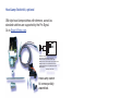
1
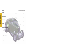
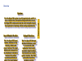
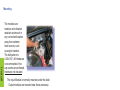
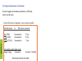
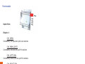
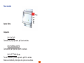
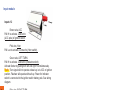
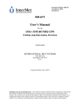
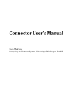
ProSignal EX
™
Smart Wiring system
Owners / Install
Manual
TM
Pro Signal Extended Set
Photo: Stacey David’s Rat Roaster
Contents
Overview
General
Series Descriptions
3
Software
15
Safety
15
Short Circuit resets
15
Engine expansion module,
optional
16
4
What’s Included
5
Mounting
6
Wire Harness block diagram
6
Power, Ground and Data Wiring.
7
Circuits that suspend
during cranking
16
Turn Signal
Connections to Controller
8
Head Lamp Switch kit,
optional
17
Service loop
8
Ignition Switch Configuration,
Controller Module
17
Head lamp module
9
Trouble shooting
18
Front module
10
Fault Status LEDs
18
Rear module
11
Glossary of Terms
19
Tail Lamp Configuration
11
INDEX
20
Input module
12
Electrical
14
M de
Made
Ma
d iin
nU
U.S.A.
.S A.
.S
Page 2
Rev. 2.0.2
Overview
The Pro-Signal©EX system has 12 input circuits and 15 or
more outputs when the optional Engine Module is used.
Pro-Signal©EX components may be used alongside legacy
fuse systems to meet any vehicle wiring requirements.
Input Module Module:
Output Modules:
The Pro-Signal©EX Input
Module attaches to the
steering column and
driver controls. The Input
Module also connects to
the dashboard indicators
and can drive either
incandescent bulbs or
LEDs. The Input Module
senses the switch
changes, actuates
dashboard indicators,
and then sends a datapacket containing the
switch states across the
system’s two-wire data
bus to the appropriate
Output Module.
The Pro-Signal©EX Output
Module distributes power
to accessories and
indicators from locally
mounted output modules.
Each module can handle
up to 4 circuits. The 100%
solid-state electronic
modules provides
switching for each circuit
according to commands
from the Input Module,
while continuously
monitoring each circuit
for short-circuits.
Va ue added
Va
Value
add
ad
ded
d functions:
fu
fu
The Pro Signal©EX has SCT (Self Canceling Turn) signals that
are reset when the turn sign switch position changes. Fog
lights will turn off when high beams are on
(Some states require this).
Status LED has been updated to include which output
channels have short circuits.
Rev. 2.0.2
Page 3
G
General
System:
Series Descriptions
While we can’t anticipate all configurations, the Pro Signal© EX
does cover most signaling configurations.
General
Pro-Signal© EX technology may be used in
any vehicle, or any system that uses 12V
power and has a need for signaling lights.
This includes auto, off road, agricultural
equipment and recreational vehicles. It
replaces traditional multi-wire harnesses,
relays, fuses, and flasher cans with solidstate, micro controller modules.
Pro-Signal© EX replaces traditional fuses by
sensing the current through an accessory and
automatically shutting
down the circuit in the
case of a short circuit.
Once the short has been
removed the module can
Inputs
manually reset. Some
Input
Power
Module
circuits automatically
Outputs
reset.
Two wire
Data cable
Power
Output
Modules
Outputs
Two wire
Data cable
Power
Output
Modules
Outputs
Two wire
Data cable
Page 4
Rev. 2.0.2
What’s Included
S
Sealed
Input
ut cable with
cconnector and 4’-8’ wires.
Colors match output functions.
C
Example: HORN input wire is
E
PINK - so is the output wire.
P
Data
a harness
h
ha
ar
arness
ar
mo
with module
connectors
assemb
connectors, assembled.
Ground wire included.
6’, 9’, and 15’ spans included;
other lengths available on line.
2 in and One
2p
Data plugs, One 2pin
3pin. Use on open module pig tail
data connectors.
Power cables, four; assembled.
Two 9’, one 12’ and one15’
Two 50amp circuit breakers to
protect power cables to modules.
Boots and lugs included. Switch
inputs and module outputs do not
require protection.
Modules,
odules, one Input
Input Module; one
Rear, one Front and one Head
Lamp Module are included.
Engine Module is optional.
V2 Rear Module shown, graphics
series, Graphite.
Rev. 2.0.2
Page 5
General
al
V2&V3 modules have a set of
faston connector cables included
with each module: 4’-10’, color
coded and printed with functions.
Mounting
Install
The modules are
moisture and vibration
resistant and mount in
any convenient location
away from extreme
heat sources, such
as engine headers.
The bolt pattern is
2.45x1.50”, #6 Hardware
is recommended. Hex
cap screws are preferred.
Hardware not included
The Input Module is normally mounted under the dash.
Output modules are mounted near there accessory.
Wire Harness block diagram
Outputs
Rear
Outputs
Inputs
Data
Outputs
Head
Lamp
Input
Module
Data
Outputs
Optional
Engine
Front
Data
O puts
Out
Data
Power
+
-
Block diagram
Note: Connect supplied power and data cables to modules
and secure wires appropriately to avoid wire chafing.
Page 6
Rev. 2.0.2
Power, Ground and Data Wiring.
Ensure all grounds are clean and secure.
se
Remove paint and
oils.
Data plugs are supplied and are necessary
to seal unused module data connectors
from moisture. The 3 pin also provides
ground for end module.
Note: Always use a circuit breaker or fuse to protect
main power cables to modules. Pro
Signal EX recommends a 40-50 amp
circuit breaker, included.
Connect no more than three modules
to a breaker.
Tip: Accessories like trunk
nk lights
and audio amplifiers that are not
supported by the Pro Signal
nal EX
may be connected to the module
power cable with an after market
fuse block.
See Smart-Wiring.com.
Rev. 2.0.2
Page 7
Install
Note:
N
ote
o te Connect all ground wires
to chassis prior to connecting
power
and data to modules.
p
Ground
wires are black and
G
assembled
asse
a
with the data cable.
Turn Signal Connections to Controller
Common toggle and momentary switches or a GM style
column can be used.
Common GM column configuration - some columns may differ.
Controller inputs
to
GM column connector
Horn (PNK)
L Turn (GRN)
R Turn (LT BLU)
Connected to
Connected to
Connected to
Install
From ignition switch battery pole
Orange 14awg
Connect to
“G” pin
“H” pin
“J” pin
“N and M” (16AWG)
See wiring schematic for details
The flasher wire on the GM column does not need to be
connected when using a GM style column.
Flash is activated through turn signal
wires.
Service loop
The data cables are supplied and pre-assembled. Modification
should be made only by an electronic technician. If the cable
is too long a “service loop” is
recommended.
rec
Pre-fabricated data
cables
cab
and kits can be ordered at
Smart-Wiring.com.
S
Sm
Page 8
Rev. 2.0.2
Head lamp module
Inputs: None
Outputs: 4
CH2 Low Beam
Controlled by White input module wire, pull Hi to activate.
CH3 High Beam
Controlled by White W/Blue stripe input module wire, pull Low to
activate.
CH4 ACC
Controlled by Brown input module wire, pull Hi to activate. Use for
low current (9.75amps or less) accessories like power radio antenna.
Tip: Pull Hi = 12V, Pull Low = Chassis Ground
Rev. 2.0.2
Page 9
Head lamp module
CH1 FOG / DRL
Controlled by Yellow input module wire, pull Low to activate.
Condition 1, ACC must be High.
Condition 2, FOG / DRL will suspend (Turn off) when High Beam is
activated.
Front module
Inputs: None
Outputs: 4
CH1 HORN
Controlled by Pink input wire, pull Low to activate.
CH2 PARK LIGHTS
Controlled by Tan input wire, pull Hi to activate.
CH3 LEFT TURN
Controlled by Green input wire, pull Hi to activate.
Front module
CH4 RIGHT TURN
Controlled by Blue input wire, pull Hi to activate.
Note: Flashers are activated by pulling both LEFT and RIGHT
TURN wires Hi simultaneously.
Front and Rear modules will alternate turn and flasher blinks to
reduce load on electrical system.
SCT, Self Canceling Turn signals
Pro Signal EX is equipped with Self Canceling Turn signals
that suspend after 90 seconds.
Reset is activated when the turn signal switch position is
changed.
Tip: Wire names are underlined in this document.
Page 10
Rev. 2.0.2
Rear module
Inputs: None
Outputs: 4
CH1 BACKUP
Controlled by Gray input wire, pull Low to activate.
CH2 PARKING LIGHTS
Controlled by Tan input wire, pull Hi to activate.
CH4 RIGHT TURN / Brake
Turn is controlled by Blue input wire, pull Hi to activate.
Brake is controlled by Violet input wire, pull Low to activate.
Note: Flashers are activated by pulling both LEFT and RIGHT
TURN wires Hi simultaneously.
Front and Rear modules will alternate turn and flasher blinks to
reduce loan on electrical system.
Tail Lamp Configuration
A 2 filament bulb and socket will combine brake, turn and
flasher into one filament. The park light will use the second
filament.
Rev. 2.0.2
Page 11
Rear Module
CH3 LEFT TURN / Brake
Turn is controlled by Green input wire, pull Hi to activate.
Brake is controlled by Violet input wire, pull Low to activate.
Input module
Inputs: 12
Brown wire, ACC
Pull Hi to activate. Connect to
(ACC pole) of Ignition switch.
Pink wire, Horn
Pull Low to activate. Connect to (Horn switch).
Green wire, LEFT TURN
Pull Hi to activate. Connect to (Indicator switch).
Activate flasher by pulling both left and right Hi simultaneously.
Note: Turn signal will not operate unless key is in ACC or Ignition
position. Flashers will operate without key. Power for Indicator
switch is connected to the ignition switch battery pole. See wiring
diagram.
Input module
Blue wire, RIGHT TURN
Pull Hi to activate. Connect to (Indicator switch).
Activate flasher buy pulling both left and right Hi simultaneously.
Note: Turn signal will not operate unless key is in ACC or Ignition
position, flashers will operate without key. Power for Indicator
switch is connected to the ignition switch battery pole. See wiring
diagram.
Violet wire, BRAKE
Pull Low to activate. Connect to (Brake switch).
Tan wire, PARK LIGHTS
Pull HI to activate. Connect to (Head light switch).
See Head Lamp switch kit for detailed instructions.
Note: Power for park lights switch can be connected to the
ignition switch BATT pole. See wiring diagram.
Gray wire, BACK UP LIGHTS
Pull Low to activate. Connect to (Reverse switch).
Page 12
Rev. 2.0.2
Orange wire, IGNITION
Pull Hi to activate. Connect to (Ignition pole) of Ignition switch.
Red wire, START
Pull Hi to activate. Connect to (Start pole) of Ignition switch.
White wire, LOW BEAM
Pull HI to activate. Connect to (Head light switch).
See Head Lamp switch kit for detailed instructions.
White W/Blue Stripe wire, HI BEAM
Pull HI to activate. Connect to (High beam switch).
See Head Lamp switch kit for detailed instructions.
Outputs: 3
CH1 IGNITION SWITCH BATTERY
Always on. This channel has automatic short circuit detect and
restart. Circuit will attempt to restart every 10 seconds after a short
circuit is detected. Connect to (Battery pole) of ignition switch.
See Ignition switch kit for detailed instructions.
Pin 1 RIGHT TURN Dash Indicator
Controlled by Blue input wire, pull Hi to activate.
LED or incandescent bulb may be used.
Pin 2 LEFT TURN Dash Indicator
Controlled by Green input wire, pull Hi to activate.
LED or incandescent bulb may be used.
Note: Flashers are activated by pulling both LEFT and RIGHT
TURN input wires Hi simultaneously.
Tip: Pull Hi = 12V, Pull Low = Chassis Ground
Rev. 2.0.2
Page 13
Input module
Yellow wire, FOG / DRL
Pull Low to activate. Connect to (Fog lamp switch).
Ground Yellow wire for DRL.
Note: FOG / DRL will deactivate when High Beams are on.
Electrical
Basic Electrical Specifications:
System specifications:
Model: EX4CH4MV2/3
12V electrical systems only
Module
Inputs
Outputs Output Power
Input
Front
Rear
Head Lamp
Optional Engine
12
0
0
0
0
3
4
4
4
3
75-200W
150W ea ch
150W ea ch
200+W ea ch
200-400W ea ch
Min-Max Limits
Inputs
Output current limits
Thermal operating
Ground to 15V
5 to 30Amps (Factory set)
-35c to +85c
Fault Status LED
Green, Once every 10 seconds: healthy, communication okay
Orange, Once every 10 seconds: module okay; no communication check data cable.
Red,
See user manual for detailed description, page 18,
Fault Status LEDs
No LED, Missing power or ground
Note: All Smart-Wiring products are for 12V
chassis ground vehicles only.
Electrical Specs
Tip: Most input wires are activated by applying +12V,
with five exceptions:
1. Horn
2. Brake
3. Back-up
4. High Beam
5. FOG / DRL
These inputs are pulled Low to activate (ground)
Page 14
Rev. 2.0.2
Software
There is nothing for the installer to program. The Pro Signal
EX was designed to be easier to install than a legacy
system. Programming isn’t needed with a legacy system, and
programming isn’t needed with the Pro Signal system.
Safety
Common Safety Functions
Short Circuit resets
1. Ignition Battery circuit (Input Module CH1) will
automatically reset after a short circuit is removed.
2. All other circuits are reset by turning off/on the
corresponding input switch.
Example: Parking lights have shorted. Remove short
circuit, turn park lights off, then back on.
Rev. 2.0.2
Page 15
Software
1. A hard short circuit shutdown is initiated by the controller
after 2 seconds and is reset by removing the short, turning
off the accessory, and then turning it back on.
2. Module outputs are shut down within 2 seconds if data
cable is disconnected.
Engine expansion module, optional
At the time of this printing Smart Wiring is offering two optional
Engine Modules.
1) For Coil and Points Ignition systems
2) For Powering an Electronic Ignition
It is our goal to provide more engine module configurations so
please visit Smart-Wiring.com new designs.
Circuits that suspend during cranking
During engine cranking the following circuits will suspend to
provide more battery current for starting.
•
Low and high beam head lamps, turn signals and parking
lights will suspend.
The following safety lights will continue to operate.
Expansion Modules, Engine
•
Flashers and brake lights will continue to operate during
cranking.
Page 16
Rev. 2.0.2
Head Lamp Switch kit, optional
GM style head lamp switches with dimmers, as well as
standard switches are supported by the Pro Signal.
Go to Smart-Wiring.com.
4
3
2 6
0 1
Pin0
Pin1
Pin2
Pin3
Pin5
Pin6
Pin7
5
7
Black 16awg, connect to chassis ground
Jumper to Pin4, Orange 16awg wire
Tan 16awg wire, connect to Dash Lights
Brown wire, connect to BATT pole of Ignition switch
Tan 20awg wire, to Input Module connector
White 20awg wire, to Input Module connector
Not used
GM Style, bottom view
He
ead Lamp switch
Head
kit comes partially
ass
assembled.
Ignition Switch Kit, optional
Battery
Ignition
Start
See ignition switch kit for more details.
Go to Smart-Wiring.com.
Note: Do not exceed the maximum current rating of the
switch
Rev. 2.0.2
Page 17
Kits, Head Lamp SW
Accessories
Trouble shooting
Problem:
Cause:
Solution:
Turn signals do not operate
Ignition switch is off or brown ACC input wire is
disconnected from ignition switch
Turn ignition switch to ACC or IGNITION.
Or connect brown wire to ignition switch.
Fault Status LEDs
Each module has a status LED to
provide system and module diagnosis:
LED cycles every 10 seconds.
One green blink indicates system and module are okay
One green blink and one red blink:
Data communication okay. (Short circuit on channel 1)
One green blink and four red blinks:
Data communication okay. (Short circuit on channel 4)
One green blink and one red blink:
Data communication okay. (Short circuit on
Channel 1). Then the next cycle one green blink
and four red blinks: Data communication okay.
Short circuit on Channel 4. (Shorts on both channels 1&4)
One orange blink:
(Loss of data communication) check data cable.
Trouble shooting
One orange blink and three red blinks:
(Loss of data communication) check data cable.
(Short circuit on Channel 3)
No LED: No power or missing ground.
Note: 2-3 cycles (20-30 seconds) will be needed for
the LED to update status.
Page 18
Rev. 2.0.2
Glossary of Terms
ACC:
Accessory
IND:
Indicator
Software:
Not hardware
SW:
Switch
AWG:
American Wire Gauge.
IGN:
Ignition
BLK:
Black
Legacy system:
Old style wire harness
BRN:
Brown
LED:
Light emitting diode
Channel:
An electrical circuit
LT BLU:
Light Blue
Control lines:
Two twisted wires from the
Input Module to all output
modules. These wires carry
the data to turn on and off all
accessories attached to the
output modules.
Low:
Ground, Chassis Ground,
GND
Camo:
Camouflage
Min-Max:
Minimum to Maximum
Conn:
Connector
MOM:
Momentary
Current:
A measure of electron flow
(AMP)
E
/R = I
NC:
Not Connected or Normally
closed
Data:
Digitally formatted
information
FAQ:
Frequently asked questions
Filament:
Illuminating wire in bulb
GM:
General Motors
GND:
Ground, Chassis Ground,
Low
GRN:
Green
GRY:
Gray
HI:
12V or Power, PWR
VIO:
Violet
V2 & V3:
Module hardware version
Yel:
Yellow
Matrix:
Software mapping grid of
system functions.
NO:
Normally Open
ORG:
Orange
OEM:
Original Equipment
Manufacture
Pig tail:
Wires from module with
connectors.
PNK:
Pink
PWR:
12V or Power, HI
Pole:
Electrical connection point
SCT:
Self Cancelling Turn signal
Rev. 2.0.2
Page 19
INDEX
A
Accessory
4
B
Bolt pattern
6
D
Data
7
E
Electrical
14
Electrical Specs 14
Expansion Modules,
Engine
16
F
FAQ
18, 19
Filament
11
FOG / DRL
9
Front module
10
G
GM column
8
Ground wires
7
H
Hardware
6
Heat sources
6
High Beam
9,10, 11, 13
Horn
8
I
Input module 12
Installation
4,6,7
K
Kits, Head Lamp
SW
17
L
LED
14
N
Note:
7, 10, 14, 17, 18
O
Output Modules 3
R
Rear Module
11
Reset
S
Safety
Short Circuit
resets
Software
15
15
15
15
Electronic Prototypes, Inc. is a development firm in Virginia, serving
commercial, industrial and military needs. Our prototyping capability quickly
links vision to reality. We do product development - always with safety and cost in
mind. Smart Wiring is a division of Electronic Prototypes, Inc.
TM
2014 Electronic Prototypes, inc. | PO box 155 | Copper Hill, VA
24079 (540) 929-0044
Smart-Wiring.com
For Sales and Tech Support
go to
Smart-Wiring.com
Or contact your distributor
Model: EX4CH4MV2/3
UserManual_ProSigEX_20p_2.0.2
Page 20
Rev. 2.0.2