1
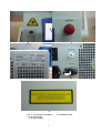
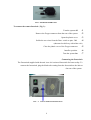
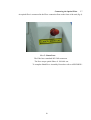
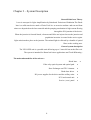
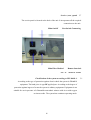
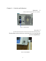
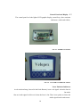
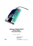
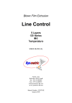
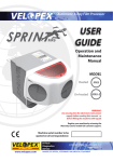
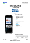
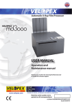
VELOPEX Dental Diode laser system User’s Manual Rev : 2 1 Table Of Contents CHAPTER1 SAFETY PRECAUTIONS 4 CHAPTER 2 – INSTALLATION 7 CHAPTER 3 SYSTEM DESCRIPTION 10 CHAPTER 4 CONTROLS AND INDICATORS 16 CHAPTER 5 OPERATING INSTRUCTIONS 19 CHAPTER 6 – LASER SURGICAL ACCESSORIES 25 CHAPTER 7 MAINTENACE 29 CHAPTER 8 TROUBLESHOOTING 31 CHAPTER 9 SPECIFICATION 33 APPENDIX 1 STRIPPING , CLEAVING 34 APPENDIX 2 ENVIRONMENTAL CONDITION FOR TRANSPORTATION AND STORAGE 37 2 List of Illustrations 7 FIG 1 LOCATION OF LABELS 9 FIG 3 – REMOTE INTERLOCK 8 FIG 4 FOOT SWITCH CONNECTION 9 FIG 5 – FIBER PORT 11 FIG 6.1 – DIODE LASER ASSEMBLY FIG 6.2 AIMING LASER DIODE ASSEMBLY 12 FIG 7 OPTICAL CONVERTER 12 FIG 8 – HEAT EXCHANGER AND TEC 13 FIG 9 DIODE LASER DRIVER 13 FIG 10 – AC/DC POWER SUPPLY 14 FIG 11 CPU AND LCD 15 FIG 12 SERVICE PANEL 16 FIG 13 MAIN ON/OFF 16 FIG 14 KEY SWITCH 17 FIG 15 INSIDE LCD PANEL 17 FIG 16 LCD AND CONTROL BOTTON 18 FIG 17 FIBER CONNECTION PORT 18 FIG 18 EMERGENCY STOP SWITCH 20 FIG 19 SELECTION FIBERS FIG 19.1 OPERATING PROGRAMS 21 FIG 20 SURGERY OPERATING SCREEN 23 FIG 21 WHITING OPERATING SCREEN 25 FIG 22 BLEACHING HAND PIECE 26 FIG 23 METAL COATED FIBER FIG 23.1 WHITENING HAND PIECE BLUE 27 FIG 24 ORANGE FLEX FIBER 28 FIG 25 FOOTSWITCH PEDAL TABLE – 1 FAULT MASSEAGE AND SYMPTOM TABLE – 2 DIO DENT SPECIFICATIONS FIG 2626.6 STRIPPING PROCESS 3 32 33 3436 Chapter 1 Operating Safety Precautions The VELOPEX diode laser system is designed to minimize accidental 1.1 exposure to hazardous Radiation. The laser beam is emitted only through the optical fiber and diverges in a wide angle (> 20 0 ). As a result, power density becomes virtually harmless a few centimeters from the fiber tip. However care should be taken to follow the instructions in the following sections. Burn Hazard 1.2 The Dio Dent radiation has wavelength of 810 nm which is invisible to the human eye and can cause third degree burns. Reflected and Direct Eye Exposure Hazards: 1.3 The laser beam emitted by the system is in the invisible part of the spectrum and can cause eye hazards to the human eye. As a precaution against accidental exposure to the output laser beam or its reflections, all personal must use appropriate safety eyewear. Warning: Do not stare into the diode laser beam or allow it to be reflected from any reflective Surface. Do not stare directly into the aiming beam. Ensure that the aiming beam is not directed at anyone’s eyes. Be careful until operating with fiber optic hand piece. If any damage occurs – stop laser immediately and change damaged parts. Safety Eyewear and Protective Clothing 1.4 The diode laser is hazardous to the human eye and skin. All personal must use safety eyewear and must ascertain that the eyewear provides adequate protection from 810 +/ 10 nm, radiation. Safety glasses and Goggles can be ordered from Medivance. All personal must use protective clothing worn should be made from a suitable flame and heat resisting material. 4 Explosion and Fire Hazard 1.5 The system is not suitable for use in the presence of flammable mixtures with air or oxygen. Do not operate in the presence of volatile solvents such as alcohol, gasoline or other. Before using system check atmospheric contamination. Flammable materials must be kept away from the laser beam. Flame retardant materials and cloth are recommended during use of the system. High voltage Hazard 1.6 The laser system utilizes 230 VAC. To avoid personal injury, do not operate the unit before ensuring that the casing is properly closed. Do not attempt to remove or disassemble the casing. Only Medivance authorized technical personal are qualified to service and maintain the unit. Using the proper power receptacle 1.7 Cable is not supplied with the unit.It is the user responsibility to use CE certified cable . The VELOPEX unit requires 230 VAC 3 Amps, and can be connected to any standard single phase main power outlet Grounding the unit 1.8 Proper grounding is essential for safe operation. The unit is ground through the grounding conductor in the power cord. Fuse replacement 1.9 The system is surge protected by slow blow fuses. The fuse is housed in the cable inlet connector. Personal Training and Medical Supervision 1.10 All persons that should be placed in control of this system must have received training to an appropriate level of laser safety. Training program must be in accordance with operation environment and national regulation acts. Personal medical supervision must be provided according to national regulation acts. 5 Warning, Certification and Identification labels: Fig 1 shows the location of the labels affixed to the unit. 6 1.11 B A C D E FIG 1 LOCATION OF LABELS A , B: FRONT PANEL D: BACK PANEL C, E: TOP COVER 7 Chapter 2 – Installation 2.1 Unpacking and Inspection The Dio Dent laser unit has passed quality assurance testing before shipment. Thus the unit should be operational upon delivery. Note: Any damage to the packing or the unit found prior to opening the package, should be reported to Medivance Equipment List: The system includes the following: · · · · · · · · · Velopex laser unit Set of keys Remote Interlock connector Foot switch + shroud One 400 um fiber optics One 320 um fiber optics for bleaching One hand piece for tooth bleaching 2 pairs of Protective glasses Operating Manual Operating Configuration The system should be placed on a table. Line Power The system is designed to operate on line voltage of 230VAT50/60 Hz. Voltage and frequency are marked clearly on the unit. A power plug compatible to the local electrical system is attached with the unit. Remote interlock connection To provide max safety the system is equipped with a remote interlock connection. The connection is suited on the rear panel (9 pin D type) (see chap 4). An external switch can be connected to this plug to create a remote interlock system. This switch should be mounted at the entrance door. If the door opens, the switch contacts also open and disable the laser Radiation. 8 FIG3 REMOTE INTERLOCK To connect the remote Interlock ( Fig 3 ): Turn the system off . 1 Remove the D type connector from the rear of the system . 2 Open the plastic cover . 3 Solder the two wires from the Door switch to pins 5&9 . 4 (shortened on delivery with white wire) Close the plastic cover of the D type connector . 5 Install to position . 6 Turn the system On . 7 Connecting the Footswitch The Footswitch supplied with the unit is an Air Activated footswitch for better safety. To connect the footswitch, plug the black tube coming from the footswitch to the inlet at the rear of the system. FIG – 4 FOOT SWITCH CONNECTING 9 Connecting the Optical Fiber 2.7 An optical fiber is connected in the Fiber connection Port on the front of the unit (fig 4). FIG 5 – FIBER PORT The Fiber has a standard 905 SMA connector The Port accept optical fibers of 200600 um . To complete Hand Piece Assembly Procedure refer to APPENDIX 1 10 Chapter 3 – System Description General Diode laser Theory Laser is acronym for Light Amplification by Stimulated Emission of Radiation.The Diode laser is a solid state device made of GaAs/GaAl As as an active medium and rear and front mirror are deposited on the laser material and the pumping mechanism is high current flowing through the P/N junction of the device. When the junction is forward biased, electrons and Holes are injected across the junction and population inversion is created in the active region. Light emission takes place at the junction. The emitted light is collected by a bundle of optical fibers to the working area. General system description The VELOPEX unit is a portable unit delivering up to 5 watts 810 nm at the fiber exit. The system is intended for Dental soft tissue applications and Tooth Whitening.: The main subassemblies of the unit are : Diode laser · Fiber relay optical system and optical path · Heat Exchanger and TEC elements · Diode laser driver · DC power supplies for the driver and the axillary units · PCU and control unit · Service ( rear ) panel · 11 3.1 Diode Laser Fig 6 shows the diode laser with the fiber bundle, which combines the Red aiming beam with the fiber bundle. FIG6.1 – DIODE LASER ASSEMBLY Aiming Diode 3.2 Fig 7 shows the Aiming Diode assembly. This assembly contain Class 1 Red laser diode, fiber optic coupler and driver plate. AIMING DIODE Safety Warning: Aiming Diode laser radiation is safe for skin and other tissues. AVOID DIRECT EYE EXPOSITION. FIG6.2 – AIMING LASER DIODE ASSEMBLY 12 Fiber relay optical system and optical path 3.3 Fig 7 shows the optical coupler, which convert the fiber bundle and the Aiming fiber into a single 300600 nm fiber optic. The fiber connection port accepts 300 micron fibers and incorporates a pair of microswitches for double safety, disabling laser emission when a fiber is inadequately connected or not connected at all. FIG –7 OPTICAL CONVERTER Heat Exchanger and TEC elements 3.3 The diode is temperature control by a TEC. The TEC is mount on a heat exchanger. The heat exchanger is responsible to remove heat from the hot side of the TEC. FIG – 8 HEAT EXCHANGER AND TEC 13 Diode laser driver ( MEG –18 ) 3.4 The diode laser driver is responsible to drive current to the laser diode according to signals from the LCD. The drive is also monitor over voltage and over temperature on the diode. FIG 9 DIODE LASER DRIVER AC/DC power supplies for the driver and the control units 3.5 The power supply is 200 watts 90264V 50/60Hz medical grade. It supplies 5V and +/12V to the diode driver and to the LDC unit. FIG – 10 AC/DC POWER SUPPLY 14 3.6 Control Panel The controls and indicators required for system operation, are located on the front of the system. The DIO DENT , incorporates fully micro controller based system with a Bakelite LCD display. Control panel functions are described in chapter 4. Main CPU Board Located together with the LCD in the Front panel FIG 11 CPU and LCD 15 Service ( rear ) panel 3.7 The service panel us located at the back of the unit. It incorporates all the required connections to the unit. Main On/Off Foot Switch Connecting Main Filter Medical Remote Interlock FIG 12 SERVICE PANEL Classification of the system according to IEC 606011. According to the type of protection against electric shock the system is CLASS 1 equipment. The hand piece is type BF applied part. According to the degree of protection against ingress of water the system is ordinary equipment. Equipment is not suitable for use in presence of a flammable anaesthetic mixture with air or with oxygen or nitrous oxide. The system has continuos operating mode. 16 3.1 Chapter 4 – Controls and Indicators Main switch 4.1 A Green switch Located on the rear of system. FIG 13 – MAIN ON/OFF Key switch 4.2 Located on the front panel. Is used to turn on the main operating manual. Warning: Remove the key from the key switch when device is not used, this will prevent its unqualified use. FIG 14 – KEY SWITCH 17 Control Panel and Display 4.3 The control panel is a bake lighted LCD graphic display, control keys, laser emission indicators ( audio and visible ) FIG 15 – INSIDE LCD PANEL FIG 16 LCD AND CONTROL BUTTONS Laser Emission Indicators A red emission lamp ( housed in the Panic Button), issue a red signal when the laser in On mode. Also an Audio signal is delivered when the laser is On. There is an option to silence the Audio signal on the main menu. 18 Fiber Connection Port 4.4 Both the diode laser beam and the red aiming beam are emitted from the laser aperture on the fiber connection port directly into the optical fiber. The fiber connection port includes fiber presence detectors, which disable laser emission in case a fiber is improperly connected or not connected at all. Refer to Chapter 2.7. FIG – 17 FIBER CONNECTION PORT Emergency Stop Switch 4.5 In case of an emergency, pressing the emergency switch shuts down the main Input Power immediately. To restart the laser, rotate the emergency switch up, turn the keyswitch off and on again. FIG – 18 EMERGANCY STOP SWITCH 19 Chapter 5 – Operating Instructions This system is type BF class 1, and as such have to be operated by M.D, according to the local laws in every country. Introduction 5.1 The chapter describes in details the operating instruction of the system. Turning on the system 5.2 Plug the unit into main power outlet 1 Connect foot switch 2 Connect Fiber. Chose fiber :diameter ( 200,300,400,600 um ) Fig19 3 Connect remote interlock 4 Wear Safety Goggles 5 Turn the Green Main power ( on Rear panel ) 6 Turn key switch on 7 Select fiber diameter 8 Set Operating procedure 9 Selecting laser power and operating Modes 10 There are 4 operating programs : Tooth whitening Endo surgery Perio surgery General surgery Each of them has factory recommended operation settings and recommended fiber diameter 20 FIG – 19 SELECTION FIBERS FIG – 19.1 OPERATING PROGRAMS 21 5.3.1 Surgery operating screen 1 2 3 4 5 6 FIG – 20 SURGERY OPERATING SCREEN Buttons description from left to right : 1. “4” Cursor that indicates the controlled parameters. Pressing the cursor moves it in a cyclic way through the system parameters “+” increased the chosen parameter value . 2 ““ decreases the chosen parameter value . 3 “StBy / Ready” . 4 “Save” The operating setup is saved in the microprocessor. Once the system is . 5 turned Off and On again –it will appear with the saved parameters. “More” Moving to the main manue screen that presents the 4 operating programs. 22 . 6 5.3.1.1 Operating Modes: The VELOPEX unit has 3 Operating Modes: CW (continuous wave) Single pulse Repeat pulse · · · · CW Mode: 1. Put the “4” on “ Mode”. 2. Use the “+” to change into “Mode:CW”. 3. Press the “On” Button. The DLD will work in “CW Mode”, after pressing the “On” Button. Time Single Pulse mode: 1. Set the “4” on “Mode” and use the “+” Button to change the mode into “Single Pulse“. 2. Move the “4” to “On time” and use “+/-” to set the exposure time. · · Repeat mode: 1. Set the “4” on “Mode”. 2. Use “+/-“ to “Repeat” Mode. 3. Move the “4” to “On Time” Mode. 4. Set “On time” with ”+/-” Buttons. 5. Set “4” to “Off Time”. 6. Use “+/-” to set “Off time”. On time Off time Signal to the Pin 6 I the 9 pin D type (Rear Panel) to set the pulse width and frequency. 23 5.3.1.2 Last Setup Selection The operator can save all operating parameters. The procedure is the following : Set the system to “Standby” Mode. . One Press “Save” Button. . Two Parameters are saved. These parameters are the new default operating parameters, every time the system is turned on. 5.3.2 Whiting operating screen FIG – 21 WHITING OPERATING SCREEN Operating Modes: 5.3.2.1 Set the operating program to whiting the recommended parameters are saved. 24 5.3.2.2 Power setting: · Place cursor ( button no. 1 ) to power. · Use + / ( button no. 2,3 ) to set designed power. · Set cursor ( button no. 1 ) to timer. · Use + / ( button no. 2,3 ) to set designed exposure time. · If you want to program press save. · To operate press stby ( button no. 4 ) · Press footswitch to operate. System Turn Off 5.4 To turn off the system : Change to “Standby” Mode. . 1 Turn “Key Switch” “Off”. . 2 Turn “Main Power” “Off”. . 3 Disconnect the “Hand Piece” from the “Optical Fiber”. . 4 Disconnect the “Optical Fiber” and store it. . 5 Disconnect the “System” from the “Power inlet”. 25 . 6 Chapter 6 – Laser Surgical Accessories 6.1 Dental suitcase: Dental suitcase is supplied as a standard accessory with Velopex system and Includes the following: Hand piece black / blue . 1 Ceramic scissors . 2 Fiber stripper . 3 Intra oral tips . 4 HAND PIECE BLACK /HAND PIECE BLUE CERAMIC SCISSORS FIBER STRIPPER INTRA ORAL TIPS FIG –22 DENTAL SUITCASE ACCESSORIES 26 6.2 Optical delivery fibers: Two types of optical delivery fibers are necessary to operate the two hand pieces. The two fibers are: Fiber model HWF 300T, metal coated fiber. . 1 Fiber model WF GE 400, orange flex fiber. . 2 The first fiber is designed for use with the tooth whitening hand piece blue (see picture no.23.1). It is comprised of a Jacketed 300 micron optical fiber, a proximal SMA connector and a SMA connector at the distal end that attaches to the tooth whitening hand piece. FIG 23 METAL COATED FIBER FIG 23.1 WHITENING HAND PIECE BLUE 27 The second fiber is designed for use with the blue/black hand piece that operating these programs: endo surgery, perio surgery and general surgery. It is comprised of a bare, reusable 400 micron fiber with a proximal free standing SMA connector. FIG – 24 ORANGE FLEX FIBER 6.3 Protective glasses: Protective safety glasses provide ample protection from laser radiation at the 810nm wavelength, it is available for use with the Velopex, and have ND> 6 at 810 nm. 28 6.4 Footswitch pedal: The footswitch supplied with the unit is a foldable, watertight device that controls laser emission. The footswitch cord is 2 meters long. To connected the footswitch, place it on the floor and plug its cord into the footswitch connection located on the service panel at the back of the unit (see fig no.11 ). Screw the cord’s threaded cap onto the connection terminal securely. FIG –25 FOOTSWITCH PEDAL 29 Chapter 7 – Maintenance 7.1 Introduction This chapter contains the maintenance instruction for the VELOPEX unit.Operators may perform routine maintenance. Other maintenance procedures that are not in this chapter are freeform only by qualified technicians. Note : Calibration procedure is done only by Medivance qualified service personal. Service Information 7.2 In communication with Medivance Service personnel, always include the model and S.N of the unit No internal maintenance or userperformed adjustments are required for this selfcontained system. All of the alignments or adjustable parameters are rigidly set at the factory. Unauthorized servicing or modification of this system, not described in this manual, may expose the operator / patient to potential electrical energy and laser radiation hazards. Improper use or adjustment of this system may invalidate the service warranty agreement. 7.3 Maintenance Cleaning and desinfestion The VELOPEX unit should be kept clean at all times. Use vacuum cleaner once a week to clean the air ways of the unit (front and rear). Hand piece and optical fibers should be cleaned immediately after use, to prevent stains from drying on the accessories. The hand piece and outer surface of the unit may be wiped clean with a soft cotton swab in 70 % alcohol. 30 Disinfecting of hand piece and fiber optic cable shall be performed by clearing with a soft cotton swab in 70% alcohol after treatment of patient. 7.4 Power meter calibration check Power meter calibration is done annually by Medivance Service Personnel. Power meter must have measurement range up to 10W CW 31 Chapter 8 Troubleshooting Introduction The VELOPEX laser system is equipped with selfcheck in routine that continuously monitors system operation. In case there is a problem a fault message will appear on the LCD display and audible beep signal is provded. Faults are divided into two: Fatal Message, . 1 Warning Message. . 2 Fatal Message will block the system to the operator and the operator should turn the system “Off” by the Main Switch. Warning Message will direct the operator to fix the problem, to press the “OK Button” and to continue. If the Diode Laser System malfunctions, a message will appear on the LDC. With this massage consult the following Troubleshooting Guide. Carefully follow the instruction. If the problem persists, please call Medivance Service. Barretts Green Road, London, NW10 7AP Tel 020 9865 2913 32 Troubleshooting Guide Fault Message Probable Cause Action No optical fiber is connected to Connect Fiber to port the fiber connection port Warning Fiber not connected Warning Connect footswitch or interlock Footswitch cable or interlock Disconnected or improperly connected Check footswitch or interlock connection ANY FATAL ERROR CALL SERVICE Probable Cause Symptom Display does not illuminate when keyswitch is turn on Laser emission does not occur when footswitch is pressed Laser emission indicator does not illuminate in Ready mode Aiming beam is not available · Emergency stop switch is engaged · No power from wall Outlet · Burnt fuse · Burnt display lamp Footswitch cable or interlock disconnected or improperly connected Burn indicator lamp Aiming beam system malfunction TABLE – 1 FAULT MASSEAGE AND SYMPTOM 33 Action · Turn off keyswitch, pull emergency stop switch out and restart system · Check if mains power is available and the power cable is properly plugged into wall outlet · Call service · Call service Check footswitch or interlock connection Call service Call service Chapter 9 Specifications The next table summarized “System Specs” Output Current General Output power 0.3 5W Display Wavelength 830+/ 10 nm Graphic LCD (Dots) 128X240 Internal TEC cooling Fiber Output Port SMA Measurement Display Optical Fibers 300, 320 micron Output Power NA 0.37 Operating mode Laser on –off Application Modes Tooth whitening Endo surgery Perio surgery Input General surgery Power Requirement 200 W 90264V Max Input Current (Amps) AC 3.15 A SB Input frequency (Hz) 50/60 Modulation Internal Frequency Modulation Size 28.5 W X 39 D X 16 H mm. On time : 01000 msec Weight 10 kg Off time : 01000 msec Laser Safety Features: Key switch Remote Interlock Aiming Beam 650 nm 2 mw Emergency Pushbutton On / off Footswitch Classification Class 1 Type BF TABLE – 2 DIO DENT SPECIFICATIONS 34 Appendix: 1 Stripping , cleaving of the fiber optics and introducing into the Hand piece Follow the following steps : Open the accessory box and pick: fiber stripper, hand piece, fiber cleaver and a fiber optics ( 200, 300, 400 or 600 um ) 1. FIG 26 ACCESSORIES Take the selected fiber ( example : 400 um orange color) and strip the orange coating using the fiber stripper (set at # 10 ) for length of 5 cm. . 2 Set the stripper on # 10 which is the size of the blade for stripping the coating ¨ FIG 26.1 – STRIPPER TOOL SETTING 35 Remove the Orange coating for length of 5 cm ¨ FIG 26.2 – FIBER AFTER STRIPPING PROTECTIVE COATING Set the Stripper blade on # 4 ( for 400 um fiber or # 3 for 300 um fiber etc..) ¨ FIG 26.3 – STRIPPER TOOL SETTING Remove the plastic cladding for length of 1 cm ¨ FIG 26.4 FIBER AFTER STRIPPING PLASTIC CLADDING 36 Insert The stripped fiber into the hand piece ¨ FIG 26.5 INSERT STRIPPED FIBER INTO HAND PIECE FIG 26.6 – OUTLET FIBER FROM ORAL TIPS 37 Appendix: 2. Environmental condition for transportation and storage Transportation and storage of this equipment should be done providing the following conditions: An ambient temperature range of +10ºC to +40º ) One A relative humidity range 30% to 75% ) Two An atmospheric pressure range of 700 Hpa to 1060 HPa ) Three These conditions shall be marked on the system packaging. 38