Transcript
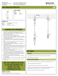
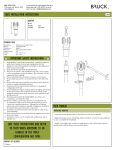
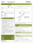
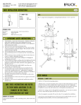
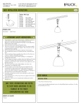
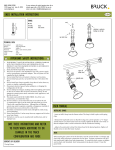
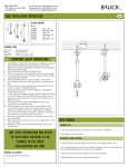
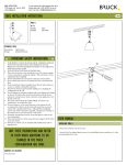
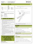
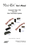
BRUCK LIGHTING SYSTEMS
15774 Gateway Circle Tustin, CA. 92780
www.brucklighting.com
For more assistance with technical questions please call our
technical support staff at (714) 259-9959. You can also
contact us by email at [email protected].
ENZIS INSTALLATION INSTRUCTIONS
POWER FEED
1 5/8"
1 3/4"
ART. NO.
140 304bz
140 304mc
A
bronze
matte chrome
1"
correct
B
wrong
TECHNICAL DATA
Description:
Design:
Dimensions:
Material:
Supply Voltage:
Current:
Load:
Wire Size:
power feed with 2” J-box for power delivery.
Jorg Westerheide
length 1 5/8”
PBT 30% glass contacts. Brass nickel plated.
12V
max. 25 A/ circuit
mas. 300W/ circuit
8 - 10 AWG
F
C
IMPORTANT SAFETY INSTRUCTIONS
2.
3.
4.
5.
6.
7.
8.
9.
10.
11.
12.
13.
THIS PRODUCT MUST BE INSTALLED BY A PERSON FAMILIAR
WITH THE CONSTRUCTION AND OPERATION OF THE
PRODUCT AND THE HAZARDS INVOLVED, IN ACCORDANCE
WITH LOCAL NEC CODE.
FOR USE WITH ENZIS RAIL NETWORK ONLY.
The Enzis rail system is not intended for use with a power supply
cord or convenience receptacle adaptor. This rail system is to be
supplied by Bruck Lighting.
Do not install the Enzis rail system in damp or wet locations.
Do not install any part of a rail system less than 5 feet above the
floor.
Do not install any fixture assembly closer than 6 inches from any
curtain, or similar combustible material.
Disconnect electrical power before adding to or changing the
configuration of the rail.
Do not attempt to energize anything other than lighting rail fixtures
on the rail. To reduce the risk of fire and electric shock, do not
attempt to connect power tools, extension cords, appliances, and
the like to the rail.
This track system MUST BE HARD WIRED. For all the wire
connections, use Listed Wire Nuts.
Do not connect a rail to more than one circuit unless the rail
is constructed so that it can be used with more than on circuit.
Check with a qualified electrician. Although the rail lighting
system may seem to operate acceptably, a dangerous overload of
the neutral may occur and result in a risk of fire.
Secondary connections must be clean and tight to avoid arcing
and overheating!
Power Feed must be 3 inches away from any support and 6 inches
away from fixture.
Warranty is void in case of unauthorized modifications and/ or
improper use.
SAVE THESE INSTRUCTIONS AND REFER
TO THEM WHEN ADDITIONS TO OR
CHANGES IN THE TRACK
CONFIGURATION ARE MADE
CONTENTS OF DELIVERY
1 power feed, allen wrench, and wire crimps
1cm
1.
D
G
E
USER MANUAL
INSTALLING POWER FEED
- Remove power feed cap (A) push power feed body (B) onto track.
- Screw power feed cap (A) onto the power feed body (B).
- Insert screw driver into power feed through hole (F) on the contact screws (C) and
tighten only until they make full contact. Each contact screw (C) must be equally offset
on both sides of the track.
- Make a final turn on each contact screw (C) until the through holes (F) are in a
vertical position.
CAUTION: OVERTIGHTING WILL STRIP THE THREADS ON THE POWER FEED AND
CAUSE POOR CONTACT RESULTING IN OVERHEATING AND FAILURE OF SYSTEM.
- Insert power supply cable and ferrule (G) into power feed throught (F). Tighten set
screws (E) to finish power feed installation to Enzis track.
TO REMOVE THE POWER SUPPLY
- Loosen the set screws (E) remove the power supply cable (G) and loosen the contact
screws (C).
- With a flat tool, push back the contact plates (D) until it clears the track.
- Unscrew the power feed cap (A) and remove the power feed.
When turning on the system for the first time, turn off the system after 15 minutes
and check ALL track and power connections for any heat.