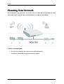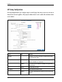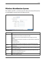
1
4-Port Wireless G Router User Manual Legal Notice 2007 © All rights reserved. Version 1.1 No part of this document may be reproduced, republished, or retransmitted in any form or by any means whatsoever, whether electronically or mechanically, including, but not limited to, by way of photocopying, recording, information recording, or through retrieval systems without the express written permission. We reserve the right to revise this document at any time without the obligation to notify any person and/or entity. All other company or product names mentioned are used for identification purposes only and may be trademarks of their respective owners. LIMITATION OF LIABILITY AND DAMAGES THE PRODUCT AND THE SOFTWARES WITHIN ARE PROVIDED "AS IS," BASIS. THE MANUFACTURER AND MANUFACTURER’S RESELLERS (COLLECTIVELY REFERRED TO AS “THE SELLERS”) DISCLAIM ALL WARRANTIES, EXPRESS, IMPLIED OR STATUTORY, INCLUDING WITHOUT LIMITATION THE IMPLIED WARRANTIES OF NON-INFRINGEMENT, MERCHANTABILITY OR FITNESS FOR A PARTICULAR PURPOSE, OR ANY WARRANTIES ARISING FROM COURSE OF DEALING, COURSE OF PERFORMANCE, OR USAGE OF TRADE. IN NO EVENT WILL THE SELLERS BE LIABLE FOR DAMAGES OR LOSS, INCLUDING BUT NOT LIMITED TO DIRECT, INDIRECT, SPECIAL WILLFUL, PUNITIVE, INCIDENTAL, EXEMPLARY, OR CONSEQ UENTIAL, DAMAGES, DAMAGES FOR LOSS OF BUSINESS PROFITS, OR DAMAGES FOR LOSS OF BUSINESS OF ANY CUSTOMER OR ANY THIRD PARTY ARISING OUT OF THE USE OR THE INABILITY TO USE THE PRODUCT OR THE SOFTWARES, INCLUDING BUT NOT LIMITED TO THOSE RESULTING FROM DEFECTS IN THE PRODUCT OR SOFTWARE OR DOCUMENTATION, OR LOSS OR INACCURACY OF DATA OF ANY KIND, WHETHER BASED ON CONTRACT, TORT OR ANY OTHER LEGAL THEORY, EVEN IF THE PARTIES HAVE BEEN ADVISED OF THE POSSIBILITY OF SUCH DAMAGES. THE ENTIRE RISK AS TO THE RESULTS AND PERFORMANCE OF THE PRODUCT OR ITS SOFTWARE IS ASSUMED BY CUSTOMER. BECAUSE SOME STATES DO NOT ALLOW THE EXCLUSION OR LIMITATION OF LIABILITY FOR DAMAGES, THE ABOVE LIMITATION MAY NOT APPLY TO THE PARTIES. IN NO EVENT WILL THE SELLERS’ TOTAL CUMULATI VE LIABILITY OF EACH AND EVERY KIND IN RELATION TO THE PRODUCT OR ITS SOFTWARE EXCEEDS THE AMOUNT PAID BY CUSTOMER FOR THE PRODUCT. Declaration of Conformity Marking by the above symbol indicates compliance with the Essential Requirements of the R&TTE Directive of the European Union (1999/5/EC). This equipment meets the following conformance standards: EN300 328, EN301 489-17, EN60950 Countries of Operation and Conditions of Use in the European Community This device is intends to be operated in all countries of the European Community. Requirement is for indoors vs. outdoors operation, license requirements and allowed channels of operation apply in some countries as described in this document. Note: The user must use the configuration utility provided with this product to check the current channel of operation and confirm that the devices operating in conformance with the spectrum usage rules for the European Community countries as described below. If operation is occurring outside of the allowable channels as indicated in this guide, then the user must cease operating the product and consult with the local technical support staff responsible for the wireless network. This device may be operated indoors or outdoors in all countries of the European Community using the 2.4GHz band: Channels 1 – 13, except where noted below: · In Italy the end-user must apply for a license from the national spectrum authority to operate this device outdoors. · In France outdoor operation is only permitted using the 2.4 – 2.454 GHz band: Channels 1 – 7. Page 2 of 129 User Manual Contents About the Router ........................................................................................................................... 7 Requirements ............................................................................................................... 8 Package Contents ......................................................................................................... 8 Device Design................................................................................................................ 9 Getting Started ............................................................................................................................ 11 Planning Your Network............................................................................................ 12 Remove or Disable Conflicts .................................................................................... 13 Internet Sharing, Proxy, and Security Applications.............................................................................................. 13 Configuring TCP/IP Settings ............................................................................................................................... 14 Configuring Internet Properties ..........................................................................................................................14 Removing Temporary Internet Files ....................................................................................................................15 Setup the Device......................................................................................................... 16 Connecting to the Internet ....................................................................................... 17 Connecting Via the Web Interface ........................................................................................................................17 Connecting Via the Setup Utility Wizard ..............................................................................................................22 Connecting Wireless Devices ................................................................................... 23 About the Web Interface............................................................................................................. 24 Accessing the Web Manager ..................................................................................... 24 Menus........................................................................................................................... 24 Setup Menu.........................................................................................................................................................25 Basic Menu .........................................................................................................................................................26 Advanced Menu ...................................................................................................................................................27 Wireless Menu.....................................................................................................................................................28 Security Menu .....................................................................................................................................................29 Status Menu........................................................................................................................................................30 Help Menu ..........................................................................................................................................................31 Setup Menu................................................................................................................................... 32 Basic Menu ................................................................................................................................... 33 Home ............................................................................................................................ 34 Connection Information......................................................................................................................................34 Page 3 of 129 User Manual Router Information.............................................................................................................................................34 Local Network Information..................................................................................................................................34 Wireless Network Information.............................................................................................................................34 Quick Start.................................................................................................................. 35 LAN Configuration ..................................................................................................... 39 Diagnostics.................................................................................................................. 40 Ping Test.............................................................................................................................................................40 Full Modem Test .................................................................................................................................................41 Advanced Menu ............................................................................................................................ 42 WAN.............................................................................................................................. 43 New Connection...................................................................................................................................................43 ADSL Modulation ................................................................................................................................................50 Connection Scan..................................................................................................................................................51 LAN ............................................................................................................................... 52 LAN Configuration ..............................................................................................................................................52 LAN Group Configuration....................................................................................................................................54 Assign ISP DNS, SNTP .........................................................................................................................................56 LAN Clients .........................................................................................................................................................56 Applications................................................................................................................ 58 Universal Plug and Play......................................................................................................................................59 Simple Network Timing Protocol .........................................................................................................................60 Simple Network Management Protocol ................................................................................................................62 IGMP Proxy.........................................................................................................................................................63 TR-068 WAN Access.............................................................................................................................................65 TR-069 ............................................................................................................................................................... 66 NAT Services........................................................................................................................................................67 DNS Proxy...........................................................................................................................................................68 Dynamic DNS Client ............................................................................................................................................69 Easy Connect Configuration.................................................................................................................................70 Port Triggering ...................................................................................................................................................72 Port Forwarding..................................................................................................................................................73 Bridge Filters......................................................................................................................................................74 Web Access Control..............................................................................................................................................75 SSH Access Control ..............................................................................................................................................76 Quality of Service ...................................................................................................... 78 Page 4 of 129 User Manual Egress .................................................................................................................................................................80 Ingress................................................................................................................................................................ 82 QoS Shaper Configuration ...................................................................................................................................89 Policy Routing Configuration .............................................................................................................................. 93 Routing........................................................................................................................ 96 Static Routing .....................................................................................................................................................96 Dynamic Routing ................................................................................................................................................97 Routing Table .....................................................................................................................................................98 System Password ....................................................................................................... 99 Firmware Update ..................................................................................................... 100 Restore to Default .................................................................................................... 100 Wireless Menu ........................................................................................................................... 101 Setup .......................................................................................................................... 102 Configuration ........................................................................................................... 103 Multiple SSID............................................................................................................ 104 Wireless Security..................................................................................................... 105 WEP ..................................................................................................................................................................105 802.1x .............................................................................................................................................................. 107 WPA..................................................................................................................................................................108 Wireless Management ............................................................................................. 108 Access List.........................................................................................................................................................109 Associated Stations............................................................................................................................................109 Wireless Distribution System ............................................................................... 111 Security Menu............................................................................................................................ 113 IP Filters ................................................................................................................... 114 LAN Isolation ............................................................................................................ 116 URL Filters................................................................................................................ 117 Status Menu ............................................................................................................................... 118 Connection Status.................................................................................................... 119 System Log ................................................................................................................ 120 Remote Log................................................................................................................ 121 Network Statistics................................................................................................... 123 DDNS Update Status................................................................................................. 124 DHCP Clients............................................................................................................. 125 Page 5 of 129 User Manual QoS Status ................................................................................................................. 125 Modem Status ........................................................................................................... 126 Product Information .........................................................................................................................................126 WDS Report............................................................................................................... 127 Help Menu .................................................................................................................................. 128 Page 6 of 129 User Manual About the Router Your router offers an easy way of integrating your computer and other network devices into a single network. Here are some of the benefits you can obtain from using the router in your home or office: Integrated Modem Feature Your router is an ideal solution for high speed Internet connectivity. It is capable of handling the fastest data transfer speed from your Internet provider and sharing this within your local network devices. Top Notch Security Your router utilizes built-in firewall security to block service attacks. For added flexibility, it can be modified to allow specific applications to pass through while blocking intrusive threats at the same time. Intuitive User Interface Applying changes on the router settings can be done easily using a Web browser. The router uses a simplified user interface that allows you to apply the configurations you want for the various features of the router. Your router will serve as the central figure in establishing your local area network (LAN) by using a combination of hardware and software. The hardware includes the cables, wireless access points, and Ethernet ports that create the path to connect your devices. The software part includes the applications that manage the flow of information in these devices. You can complete the basic installation and Internet connection within 8 minutes. Some more time is needed if you intend to utilize more advanced functions but it can be worth it. Advanced features like port forwarding will help you create your own web server to store your Web site, Dynamic DNS allows you to access your network from the Internet, and remote access enables you to configure your router settings from different locations. Once installation is complete, it will be much more easier for you to enjoy voice communication, high speed Internet, and data/audio/video sharing within your network. Page 7 of 129 User Manual Requirements Your computer must meet the following minimum requirements. Any operating system can be used Internet Explorer 4.0 or Netscape Navigator 3.02 233MHz processor CD-ROM Drive Ethernet network adapter An active DSL Internet account Package Contents Package contents are listed below. For any missing items, please contact your dealer immediately. Product contents vary for different models. Router Ethernet cable Telephone cable 9V Power Adapter Easy Start Guide Resource CD Page 8 of 129 User Manual Device Design Label 1 2 3 4 POWER ETHERNET 1-4 WiFi DSL Action Description Off No power is supplied to the device Steady light Connected to an AC power supply Off No Ethernet connection Steady light Connected to an Ethernet port Blinking light Transmitting/Receiving data Off Access point is disabled Steady light Access point is enabled Blinking light Transmitting/Receiving data Off No DSL signal Blinking light Establishing DSL signal Steady light DSL signal is established Page 9 of 129 User Manual 5 INTERNET Off No Internet connection Green light Connected to the Internet Green Blinking light Transmitting/Receiving data Red Blinking light Cannot establish Internet connection 6 DSL Connecting the telephone cable 7 ETHERNET 1-4 Connecting with computers/devices through Ethernet cable 8 RESET Resetting the device. Press for 10 seconds to reset. 9 9V DC Connecting with the 9V power adapter 10 ON/OFF Switching the device on/off 11 Antenna Sending/receiving wireless signals Page 10 of 129 User Manual Getting Started Setting up the device is easy. The flowchart below provides an outline of the steps needed to complete the installation. Brief descriptions appear beside each step. Detailed instructions are provided in the subsequent pages. Plan your Network Remove/Disable Conflicts Setup the Router Connect to the Internet You may need to remove or disable some applications before installation. Connect the telephone cables, Ethernet cables, and power adaptor. Use either the Quick Start or the Setup Utility Wizard ro connect to the Internet. Web Interface Resource CD Use Quick Start Use Setup Utility Ready to Use Page 11 of 129 User Manual Planning Your Network Before moving ahead to setup your network, it is a good idea to draw out a network diagram to help identify your network devices and plan out how to connect these devices. The illustration below is an example of a network diagram. To create a network diagram: For wireless devices, identify the wireless devices you want to include in the network For wired devices, identify which router port you want to use for each device. Page 12 of 129 User Manual Remove or Disable Conflicts To make sure the router installation moves on smoothly, you need to remove or disable conflicts that may interfere the installation. Probable conflicts may include: Internet sharing applications Proxy software Security software TCP/IP settings Internet properties Temporary Internet files Internet Sharing, Proxy, and Security Applications Internet sharing, proxy software, and firewall applications may interfere with the router installation. These should be removed or disabled before start the installation. If you have any of the following or similar applications installed on your computer, remove or disable them according to the manufacturer’s instructions. Internet Sharing Applications Proxy Software Security Software Microsoft Internet Sharing WinGate Symantec WinProxy Zone Alarm Page 13 of 129 User Manual Configuring TCP/IP Settings Check if your computer uses the default TCP/IP settings. To check the TCP/IP properties: 1. Click Start and then select Run. This opens the Run dialog box. 2. Type control ncpa.cpl and then click OK. This opens Network Connections. 3. Right-click LAN and then select Properties. This opens the Local Area Connection Properties dialog box. 4. Select Internet Protocol (TCP/IP) and then click Properties. This opens the Internet Protocol (TCP/IP) dialog box. 5. Select Obtain an IP address automatically. 6. To close the Internet Protocol (TCP/IP) dialog box, click OK. 7. To close the Local Area Connection Properties dialog box, click OK. Configuring Internet Properties To set the Internet Properties: 1. Click Start and then select Run. This opens the Run dialog box. 2. Type control inetcpl.cpl and then click OK. This opens Internet Properties. 3. Click Connections tab. 4. In the Dial-up and Virtual Private Network settings pane, select Never dial a connection. 5. To close Internet Properties, click OK. Page 14 of 129 User Manual Removing Temporary Internet Files Temporary Internet files are files from Web sites that are stored in your computer. Delete these files to clean the cache and remove footprints left by the Web pages you visited. To remove temporary Internet files: 1. Click Start and then select Run. This opens the Run dialog box. 2. Type control and then click OK. This opens Control Panel. 3. Double-click Internet Options. 4. In the Temporary Internet Files pane, click Delete Cookies. 5. Click Delete Files. 6. To close Internet Properties, click OK. Page 15 of 129 User Manual Setup the Device When installing the router, find an area where there are enough electrical outlets for the router, the main computer, and your other computer devices. To setup the router: 1. Plug one end of the Ethernet cable to the router’s ETHERNET port and then plug the other end to the Ethernet port in your computer. 2. If you have another device you need to connect through wire into the router, use another piece of Ethernet cable. Plug one end of the Ethernet cable to an available Ethernet port in the router and then plug the other end to the Ethernet port of the device. 3. Plug one end of the telephone cable to the POTS Splitter’s ADSL port and then plug the other end to the router’s DSL port. POTS Splitter Your phone line carries with it both phone calls and Internet signals. When you are using the Internet and performing a voice call at the same time, the connection produces irritating high-pitched tones. Installing a Plain Old Telephone Service (POTS) splitter separates the two signals and eliminates the noise. To setup the telephone POTS Splitter: a. Locate the phone jack in your house. b. Insert the POTS Splitter into the phone jack. c. Plug one end of the telephone cable to the POTS Splitter’s TEL port and then plug the other end to the telephone. 4. Connect the power adapter to the router’s 9V DC port and then plug it to the electrical outlet. 5. Press ON. Page 16 of 129 User Manual Connecting to the Internet There are two ways to connect to the Internet. You can either use the Web Interface or the Utility Wizard. Note: An established DSL signal is required before you can make an Internet connection. To check if you have an established DSL signal, the DSL LED on the router’s front panel should be steadily on. If it continuous to blink for at least five minutes, please report this to your Internet service provider. Connecting Via the Web Interface To connect to the Inter via the Web Interface: 1. Open your browser. 2. Enter 192.168.1.1 in the address field and then press Enter. This opens the Setup Page of the web interface. Setup Page 3. Click Step 1: Internet Login Account Setting. This opens the Internet Login Account Setting page. Internet Login Account Setting Page 4. Type the User ID, Password, Protocol, VP1, and VCI for your account. These are the account information from your Internet service provider. Page 17 of 129 User Manual For ISPs with BT phone lines (Most UK ISPs) For Kingston Communications (Karoo) Page 18 of 129 User Manual 5. Click Next. This opens the Wireless LAN Configuration Page. Wireless LAN Configuration Page 6. Type an SSID, and then select a Country Standard and Wireless Channel. 7. Select Yes or No to specify if you want to hide your wireless network name or not. Page 19 of 129 User Manual 8. Click Next. This opens the Wireless LAN Security page. Wireless LAN Security 9. Select Enable Wireless Security. 10. Enter an Encryption Key or click Generate to allow the router to create an alphanumeric encryption key for you. The Encryption key will be used to establish the wireless network connection of wireless devices. 11. Click Next. This opens the System Password Page. System Password Page 12. Select Enable Authentication, and then type your User Name, Password, and Confirm Password. 13. Click Next. This opens the Summary page. 14. Click Finish. 15. Click OK when a dialog box opens asking if you want to save and restart. Page 20 of 129 User Manual The router will take about two minutes to save the settings and establish a connection with your Internet service provider. Afterwards, the Basic Home page opens to give you a summary of the account settings. Page 21 of 129 User Manual Connecting Via the Setup Utility Wizard The Setup Utility Wizard can be used to configure your router. However, this only runs on Windows operating systems with a CDROM drive. To connect to the Internet using the Setup Utility Wizard: 1. Insert the Resource CD into your CD-ROM. 2. If the utility does not launch automatically, click the Start button and then select Run, type D:\Setup.exe (where D: is your CD-ROM drive), and then click OK. This opens the Setup Utility. 3. Select your router model and then follow the installation procedure. 4. After a successful connection, on the router’s front panel, INTERNET lights up. Page 22 of 129 User Manual Connecting Wireless Devices After you setup the device settings through the main computer, you can connect other devices with wireless capabilities. Wireless devices relieve you from the task of laying out cables and allow you to use the Internet connection from your router. To the connect with wireless devices: 1. Turn on your wireless device. 2. Open the software you use to detect a wireless connection. This opens a window to ask for the connection settings. 3. Enter the connection settings. These settings are defined in your router during setup. For more details about wireless connections, please refer to Wireless Menu. Page 23 of 129 User Manual About the Web Interface The Web Interface is used to configure the router settings. Accessing the Web Manager To access the Web Manager: 1. Open a browser. 2. Enter the router’s IP Address. The default IP Address is 192.168.1.1. 3. When authentication is enabled, the log in page will appear. In the login page, enter the User Name and Password. Menus The web interface includes the following menus: Setup Menu Basic Menu Advanced Menu Wireless Menu Security Menu Status Menu Help Menu Page 24 of 129 User Manual Setup Menu The Setup menu is used to complete the initial device configuration. Setup Menu Page 25 of 129 User Manual Basic Menu The Basic Menu provides the Home, Quick Start, LAN Configuration, and Diagnostics links. Basic Menu Page 26 of 129 User Manual Advanced Menu The Advanced mode provides advanced configuration settings for existing connections. At least one WAN connection must be configured before implementing advanced WAN configuration features. At least one LAN group must be defined before implementing advanced LAN configuration features. Advanced Menu Page 27 of 129 User Manual Wireless Menu Wireless Menu allows you to configure the wireless settings. Wireless Menu Page 28 of 129 User Manual Security Menu Security Menu allows you to configure security tools like IP Filters and LAN Isolation. Security Menu Page 29 of 129 User Manual Status Menu The Status Menu provides the status for different connections or interfaces. Status Menu Page 30 of 129 User Manual Help Menu The Help Menu provides documentation about various router features. Help Menu Page 31 of 129 User Manual Setup Menu The Setup Menu provides step by step instructions on how to configure the router settings. Please refer to Connecting Via the Web Interface. Setup Menu Page 32 of 129 User Manual Basic Menu The options for the Basic Menu include: Home Quick Start LAN Configuration Diagnostics Basic Menu Page 33 of 129 User Manual Home The Home page provides a one-page summary about the Connection Information, Router Information, Local Network, and Wireless Network settings. Connection Information The Connection Information pane gives you an idea about the status of your Internet connection. This pane includes a Connect/Disconnect button. When clicked, the router makes an attempt to connect to the Internet using the parameters saved in the router. Router Information This pane provides all the necessary information to determine the model, firmware version, build, Ethernet MAC Address, Wireless MAC Address, NAT status, and Firewall status. Local Network Information The Local Network pane displays the current IP address of the router. It also provides the DHCP status, DHCP Range, and Ethernet status. Wireless Network Information This pane displays the current configuration settings for the router’s access point. Page 34 of 129 User Manual Quick Start Quick Start gives you the ability to instantly connect to the Internet. To connect to the Inter via the Web Interface: 1. Open your browser. 2. Enter 192.168.1.1 in the address field and then press Enter. This opens the Setup Page of the web interface. Setup Page 3. Click Step 1: Internet Login Account Setting. This opens the Internet Login Account Setting page. Internet Login Account Setting Page 4. Enter the User ID, Password, Protocol, VP1, and VCI for your account. These are the account information from your service provider. Page 35 of 129 User Manual For ISPs with BT phone lines (Most UK ISPs) For Kingston Communications (Karoo) Page 36 of 129 User Manual 5. Click Next. This opens the Wireless LAN Configuration Page. Wireless LAN Configuration Page 6. Enter an SSID, Country Standard, and Wireless Channel. 7. Select Yes or No to specify if you want to hide your wireless network name or not. 8. Click Next. This opens the Wireless LAN Security page. Wireless LAN Security Page 37 of 129 User Manual 9. Select Enable Wireless Security. 10. Enter an Encryption Key or click Generate to allow the router to create an alphanumeric encryption key for you. The Encryption key will be used to establish the wireless network connection of wireless devices. 11. Click Next. This opens the System Password Page. System Password Page 12. Select Enable Authentication then enter User Name, Password, and Confirm Password. 13. Click Next. This opens the Summary page. 14. Click Finish. 15. Click OK when a dialog box opens asking if you want to save and restart. The router will take about two minutes to save the settings and establish a connection with your Internet service provider. Afterwards, the Basic Home page opens to give you a summary of the account settings. Page 38 of 129 User Manual LAN Configuration LAN Group Configuration allows you to configure settings for each LAN group. Notice that you can also view the status of advanced services that can be applied to a LAN group. Green indicates that the service is enabled, while red indicates that the service is disabled. LAN Group Configuration Page 39 of 129 User Manual Diagnostics Diagnostic Test is used for investigating whether the router is properly connected to the WAN Network. This test may take a few seconds to complete. To perform the test, select your connection from the list and press the Test button. Before running this test, make sure you have a valid DSL link. To run diagnostic test: 1. Select the Basic Menu and then click Diagnostics. This opens the Diagnostics page. 2. Click Test. The test status will appear after running the diagnostic test. If a test failed, click Help to get the solution. Ping Test Once you have your router configured, it is a good idea to make sure you can ping the network. If you can ping an IP on the WAN side successfully, you should be able to surf the Internet. To perform a ping test: 1. Select the Basic Menu and then click Diagnostics. 2. Click Ping Test. This opens the Ping Test page. 3. Change or leave the default settings of the following fields: Enter the IP address to ping Packet size Page 40 of 129 User Manual Number of echo request 4. Click Test. The ping results are displayed in the page. If the ping test was successful, it means that the TCP/IP protocol is up and running. If the Ping test failed, you should restart the router. Full Modem Test This test is used to check if your modem is properly connected to the network. To perform a Full Modem test: 1. Select the Basic Menu and then click Diagnostics. 2. Click Full Modem Test. This opens the Modem Test page. Select your connection and then click Test. Page 41 of 129 User Manual Advanced Menu This chapter provides advanced configuration options for your router. Advanced Menu Page 42 of 129 User Manual WAN Wide Area Network refers to the configurations you perform to establish an Internet connection. There are several types of WAN connections that require different settings. New Connection Your router supports the creation of new connections. If you have multiple virtual connections, you may need to utilize the static routing capabilities of the modem to pass data correctly. WAN connections types include: PPPoE Connection PPPoA Connection Static Connection DHCP Connection Bridge Connection CLIP Connection Page 43 of 129 User Manual PPPoE Connection PPP, or point-to-point protocol, is a method of establishing a network connection/session between network hosts. PPPoE is a protocol for encapsulating PPP frames in Ethernet frames and is described in RFC 2516. PPPoE provides the ability to connect to a network of hosts over a simple bridging access device to a remote access concentrator. With this model, each router uses its own PPP stack. Access control, billing, and type of service control can all be done on a per-user rather than per-site basis. New PPPoE Connection Setup Page 44 of 129 User Manual PPPoA Connection PPPoA is also known as RFC 2364. It is a method of encapsulating PPP packets in ATM cells that are carried over the DSL line. PPP, or point-to-point protocol, is a method of establishing a network connection/session between network hosts. It usually provides a mechanism of authenticating users. Logical link control (LLC) and virtual circuit (VC) are two different methods of encapsulating the PPP packet. Contact your service provider to determine which encapsulation is being used on your Internet connection. New PPPoA Connection Setup Page 45 of 129 User Manual Static Connection Static connection type is used whenever a known static IP address is assigned to the router. Additional addressing information such as the subnet mask and the default gateway must also be specified. Up to three domain name server (DNS) addresses can be identified. These servers resolve the name of the computer to the IP address mapped to it and thus enable you to access other web servers by typing the symbolic name (host name). New Static Connection Setup Page 46 of 129 User Manual DHCP Connection DHCP allows the router to automatically obtain the IP address from the server. This option is commonly used in when the IP is dynamically assigned and is not known prior to assignment. New DHCP Connection Setup Page 47 of 129 User Manual Bridge Connection A bridge connection does not assign any IP address to the WAN interface. NAT and firewall rules are not enabled. This connection method makes the router act as a bridge for passing packets between the WAN interface and the LAN interface. New Bridge Connection Setup Page 48 of 129 User Manual CLIP Connection Classical IP over ATM (CLIP) Connection Setup page (CLIP) provides the ability to transmit IP packets over an ATM network. CLIP support encapsulates an IP datagram in an AAL5 PDU frame using RFC 2225 and it uses an ATM-aware version of the address resolution protocol (ATMARP). CLIP Connection Setup Page 49 of 129 User Manual ADSL Modulation ADSL Modulation allows you to select any combination of DSL training modes. Leave the default value if you are unsure or the service provider did not provide this information. In most cases, this screen should not be modified. ADSL Modulation Page 50 of 129 User Manual Connection Scan This feature helps users to detect the PVC settings provided by the service provider. Before the router can begin scanning the connection, the telephone line has to be plugged into the router. Connection Scan To perform connections scan: 1. Select the Advanced Menu. 2. Select WAN > Connection Scan. 3. Click Scan. Page 51 of 129 User Manual LAN The router is preconfigured to automatically provide IP addresses to all the computers in the Local Area Network (LAN). Your router allows you to create and configure LAN groups. LAN Configuration Your router’s default IP address and subnet mask are 192.168.1.1 and 255.255.255.0, respectively. This subnet mask allows the router to support 254 users. If you want to support more users, you need to edit the subnet mask but remember that the DHCP server is defaulted to only give out 255 IP addresses. If you change your gateways’ IP address and you have DHCP enabled, the DHCP configuration must reside within the same subnet. The default gateway is the routing device used to forward all traffic that is not addressed to a station within the local subnet. Your ISP will provide you with the default gateway Address. LAN Configuration To configure the LAN groupings: 1. Select the Advanced Menu. 2. Select LAN > LAN Configuration. Page 52 of 129 User Manual 3. Select ETHERNET in LAN group 1 and then click < Remove. No packets will be sent to the ETHERNET interface because it does not belong to any LAN group. 4. Select ETHERNET from Interfaces and then click Add > under LAN group 2. Just like in LAN group 1, Configure will appear in LAN group 2 to allow the definition of additional configurations. 5. To temporarily activate the settings, click Apply. 6. To make changes permanent, click Save Settings. Page 53 of 129 User Manual LAN Group Configuration LAN Group Configuration allows you to configure settings for each LAN group. Notice that you can also view the status of advanced services that can be applied to a LAN group. Green indicates that the service is enabled, while red indicates that the service is disabled. LAN Group Configuration Category Field Unmanaged Description Unmanaged is a state when the LAN group is not configured and no IP address has been assigned to the bridge. Obtain an IP address automatically When this function is enabled, your router acts like a client and requests an IP address from the DHCP server on the LAN side. IP Address You can retrieve/renew an IP address from the DHCP server using the Release and Renew buttons. Netmask PPP IP Address The subnet mask of your router. Enables/disables PPP unnumbered feature. IP Address The IP address should be different but within the same subnet as the WAN-side IP address. Page 54 of 129 User Manual Use the following Static IP address This field enables you to change the IP address of the router. IP Address The default IP address of the router (as shown) is 192.168.1.1. Netmask The default subnet mask of your router is 255.255.255.0. This subnet allows the router to support 254 users. If you want to support a larger number of users you can change the subnet mask. Default Gateway The default gateway is the routing device used to forward all traffic that is not addressed to a station within the local subnet. Your ISP provides you with the IP address of the default gateway. Host Name The host name is used in conjunction with the domain name to uniquely identify the router. It can be any alphanumeric word that does not contain spaces. Domain The domain name is used in conjunction with the host name to uniquely identify the router. To access the web pages of the router you can type 192.168.1.1 (the IP address) or mygateway1.ar7 (Host Name.Domain). Enable DHCP Server Enables/disables DHCP. By default, your router has the DHCP server (LAN side) enabled. If you already have a DHCP server running on your network, you must disable one of the two DHCP servers. Assign ISP DNS, SNTP Enable/disables the Assign ISP DNS, SNTP feature when the DHCP server of your router has been enabled. To learn more, please refer to Assign ISP DNS, SNTP. Start IP The Start IP Address is where the DHCP server starts issuing IP addresses. This value must be greater than the IP address value of the router. For example, if the IP address of the router is 192.168.1.1 (default), then the starting IP address must be 192.168.1.2 (or higher). End IP The End IP Address is where the DHCP server stops issuing IP addresses. The ending address cannot exceed a subnet limit of 254; hence the max value for the default gateway is 192.168.1.254. If the DHCP server runs out of DHCP addresses, users do not get access to network resources. If this happens, you can increase the Ending IP address (to the limit of 254) or reduce the lease time. Lease Time The Lease Time is the amount of time that a network user is allowed to maintain a network connection to the router using the current dynamic IP address. At the end of the Lease Time, the lease is either renewed or the DHCP server issues a new IP. The amount of time is in units of seconds. The default value is 3600 seconds (1 hour). The maximum value is 999999 seconds (About 278 hours). Enable DHCP Relay In addition to the DHCP server feature, the router supports the DHCP relay function. When the router is configured as DHCP server, it assigns the IP addresses to the LAN clients. When the gateway is configured as DHCP relay, it is responsible for forwarding the requests and responses negotiated between the DHCP clients and the server. Page 55 of 129 User Manual Relay IP Server and Relay Off The IP address of the DHCP relay server. When the DHCP server and relay functions are turned off, the network administrator must carefully configure the IP address, Subnet Mask, and DNS settings of every host on your network. Do not assign the same IP address to more than one host. Also, your router must reside on the same subnet as all the other hosts. Assign ISP DNS, SNTP When you enable the DHCP server, the router dynamically assigns IP addresses to computers in the local network. The router provides its own LAN IP address (192.168.1.1) as both the gateway and the DNS server. The router has a choice of advertising its own IP address (192.168.1.1) as the DNS server or providing the DNS that was received from the WAN. This can be configured by enabling/disabling Assign ISP DNS SNTP on the LAN Group Configuration page. Note: ISP DNS, SNTP only applies when the DHCP server is enabled on the LAN Group Configuration page. LAN Clients LAN Clients allows you to view and add computers in a LAN group. Each computer either has a dynamic or static (manuallyconfigured) IP address. You can add a static IP address (belonging to the router’s LAN subnet) using the LAN Clients page. Any existing static entry falling within the DHCP server's range can be deleted. LAN Clients Page 56 of 129 User Manual To add LAN Clients: 1. Select Advanced Menu. 2. Select LAN > LAN Clients. This opens the LAN Clients page. 3. Select a LAN Connection, and enter IP Address, Hostname, and MAC Address. 4. Click Apply. 5. You can convert the dynamic into a static entry by clicking Reserve, and then click Apply. 6. To temporarily implement the settings, click Apply. 7. To make changes permanent, click Save Settings. Page 57 of 129 User Manual Applications Applications include: Universal Plug and Play (UPnP) Simple Network Timing Protocol (SNTP) Simple Network Management Protocol Internet Group Management Protocol (IGMP) Proxy TR-068 WAN Access TR-069 NAT Services DNS Proxy Dynamic DNS Client Easy Connect Configuration Prot Triggering Port Forwarding Bridge Filters Web Access Control SSH Access Control Page 58 of 129 User Manual Universal Plug and Play Universal plug and play (UPnP), NAT, and firewall traversal allow traffic to pass through the router for applications using the UPnP protocol. This feature requires one active WAN connection. In addition, the computer should support this feature. In the presence of multiple WAN connections, select a connection on which the incoming traffic is present, for example, the default WAN connection. UPnP To configure UPnP: 1. Select Advanced. 2. Select Application > Enable UPnP. 3. Select the WAN Connection and LAN Connection that will use UPnP from the drop-down lists. 4. Click Apply to temporarily apply the settings. 5. To make changes permanent, click Save Settings. Page 59 of 129 User Manual Simple Network Timing Protocol Simple network timing protocol (SNTP) is a protocol used to synchronize the system time to the public SNTP servers. It uses the UDP protocol on port 123 to communicate between clients and servers. SNTP To enable SNTP: 1. Check Enable SNTP. 2. Configure the following fields: Primary SNTP Server The IP address or the host name of the primary SNTP server. This can be provided by ISP or defined by user. Secondary SNTP Server The IP address or the host name of the secondary SNTP server. This can be provided by ISP or defined by user. Tertiary SNTP Server The IP address or the host name of the tertiary SNTP server. This can be provided by ISP or defined by user. Timeout If the router failed to connect to an SNTP server within the Timeout period, it retries the connection. Polling Interval The amount of time between a successful connection with a SNTP server and a new attempt to connect to an SNTP server. Page 60 of 129 User Manual Retry Count The number of times the router tries to connect to an SNTP server before it tries to connect to the next server in line. Time Zone The time zone in which the router resides. Day Light Select this option to enable/disable daylight saving time (DST). DST is not automatically enabled or disabled. You need to manually enable and disable it. 3. Click Apply to temporarily apply the settings. 4. To make changes permanent, click Save Settings. Page 61 of 129 User Manual Simple Network Management Protocol SNMP (Simple Network Management Protocol) is a troubleshooting and management protocol, which uses the UDP protocol on port 161 to communicate between clients and servers. SNMP uses a manager MIB (management information base) agent solution to fulfill the network management needs. The agent is a separate station that can request data from an SNMP agent in each of the different system in the network. The agent uses MIBs as dictionaries of manageable objects. Each SNMP-managed device has at least one agent that can respond to the queries from the NMS. The SNMP agent supports GETS, SETS, and TRAPS for 4 groups with MIB-II: System, Interface, IP, and ICMP. The SNMP agent supports three-community names authentication. SNMP Management To access SNMP: 1. Select the Advanced Menu. 2. Select Application > SNMP. Page 62 of 129 User Manual IGMP Proxy IP hosts use Internet group management protocol (IGMP) to report their multicast group memberships to neighboring routers. Similarly, multicast routers use IGMP to discover which of their hosts belong to multicast groups. Your router supports IGMP proxy that handles IGMP messages. When enabled, your router acts as a proxy for a LAN host making requests to join and leave multicast groups, or a multicast router sending multicast packets to multicast groups on the WAN side. IGMP Proxy Multicasting is a form of limited broadcast. UDP is used to send datagram’s to all hosts that belong to what is called a Host Group. A host group is a set of one or more hosts identified by a single IP destination address. The following statements apply to host groups: Anyone can join or leave a host group at will. There are no restrictions on a host’s location. There are no restrictions on the number of members that may belong to a host group. A host may belong to multiple host groups. Non-group members may send UDP datagram’s to the host group. Multicasting is useful when the same data needs to be sent to more than one device. For instance, if one device is responsible for acquiring data that many other devices need, then multicasting is a natural fit. Note that using multicasting as opposed to sending the same data to individual devices uses less network bandwidth. The multicast feature also enables you to receive multicast video streams from multicast servers. Page 63 of 129 User Manual The IGMP Proxy page allows you to enable multicast on available WAN and LAN connections. You can configure the WAN or LAN interface as one of the following: Upstream The interface that IGMP requests from hosts are sent to the multicast router. Downstream The interface data from the multicast router are sent to hosts in the multicast group database. Ignore No IGMP request nor data multicast are forwarded. You can perform one of the two options: 1. Configure one or more WAN interface as the upstream interface. 2. Configure one or more LAN interface as the upstream interface. To configure the IGMP Proxy: 1. Select Advanced. 2. Select Application > IGMP Proxy. 3. Configure the following interfaces: Quickstart LAN group 1 4. Click Apply to temporarily apply the settings. 5. To make changes permanent, click Save Settings. Page 64 of 129 User Manual TR-068 WAN Access The TR-068 WAN Access page enables you to give temporary permission to someone (such as technical support staff) to be able to access your router from the WAN side. From the moment the account is enabled the user is expected to log in within 20 minutes, otherwise the account expires. Once the user has logged in, if the session remains inactive for more than 20 minutes, the user will be logged out and the account expires. Enable WAN Access Update To create a temporary user account for remote access: 1. Select the Advanced Menu. 2. Select Application > TR-068 WAN Access. 3. Select WAN Update. 4. Select WAN Access. 5. Enter a user name and password in the User Name and Password fields. 6. Enter a port number In the Port field (for example, 51003). To access your router remotely, enter the following URL: http(s)://10.10.10.5:51003 Syntax: http(s)://WAN IP of router:Port Number 7. Click Apply to temporarily apply the settings. 8. To make changes permanent, click Save Settings. Page 65 of 129 User Manual TR-069 The TR-069 page allows you to set up connection parameters that cannot be seen by end users. TR-069 is CPE Management Protocol from WAN side, intended for communication between a CPE and Auto-Configuration Server (ACS). The CPE WAN Management Protocol defines a mechanism that encompasses secure auto-configuration of a CPE, and also incorporates other CPE management functions into a common framework. The CPE WAN Management Protocol is intended to support a variety of functionalities to manage a collection of CPE, including the following primary capabilities: Auto-configuration and dynamic service provisioning Software/firmware image management Status and performance monitoring Diagnostics TR-069 To set TR-069: 1. Select the Advanced Menu. 2. Select Application > TR-069. 3. Leave ACS URL. 4. Select Periodic Inform Enabled and then enter the Periodic Inform Interval. Page 66 of 129 User Manual 5. Click ACS Connect to connect to the ACS. When a connection is established, the AVS updates the ACS URL, Periodic Inform Enabled, and Periodic Inform Interval. 6. To temporarily apply the settings, click Apply. 7. To make changes permanent, click Save Settings. NAT Services If the user has more than one public IP address assigned by the ISP, these additional IP addresses can be used to map to servers on the LAN. One public IP address will be used to provide Internet access to the LAN computers via NAT, serving as the primary IP address of the router. The rest will be mapped to servers on the LAN. NAT Services To access NAT: 1. Select the Advanced Menu. 2. Select Application > NAT Services. Page 67 of 129 User Manual DNS Proxy DNS Proxy determines the primary Domain Name Server and secondary DNS to be used. DNS Proxy To select the DNS Server Priority: 1. Select Advanced. 2. Select Application > DNS Proxy. 3. Select the DNS Server Priority: Only Auto Discovered DNS Servers Only User Configured DNS Servers Auto Discovered then User Configured User Configured then Auto Discovered 4. Click Apply to temporarily apply settings. 5. To make changes permanent, click Save Settings. Page 68 of 129 User Manual Dynamic DNS Client Dynamic DNS allows the user to register with a Dynamic DNS Provider. The Dynamic DNS will be linked with the WAN IP of the router even after the ISP update the WAN IP to another IP address. It can be useful in web hosting and FTP services. Dynamic DNS Client Note: The User Name/Password entered should be similar to the User Name/Password you have specified during the registration of the DNS hostname. To enable Dynamic DNS: 1. Select Advanced. 2. Select Application > Dynamic DNS Client. 3. Configure the following fields: Connection DDNS Server DDNS Client User Name Password Domain Name 4. Click Apply to temporarily apply the settings. Page 69 of 129 User Manual 5. To make changes permanent, click Save Settings. Easy Connect Configuration Easy Connect feature allow user to surf web with ease without the need to changes default configuration setting, i.e. TCP/IP, Proxy, DNS of user’s computer. Easy Connect Configuration Easy Connect features include: Auto IP All valid TCP/IP setting on user’s computer can surf web via the router without the need to change the IP address Auto DNS Any DNS IP address set at user’s computer irregardless whether the address is valid or invalid DNS, Auto DNS still allow user’s computer to surf the web. Auto NetBIOS It allows proxy server to use any NetBIOS name which the Auto NetBIOS still allow computer to surf the web with a condition that the router gateway MUST be in Private IP Ranges. Auto Proxy Refers to any valid Private IP proxy setting with any port number. For example, when you enter 1234 on the browser, Auto Proxy will still allow the computer to surf the web. Any Public IP proxy setting will assume the proxy is valid and hence Auto Proxy function will not take place. Note: The port number to be used must be specified in both the browser and the Auto Proxy Ports. Private IP Ranges Page 70 of 129 User Manual Class A: 10.0.0.0 ~ 10.255.255.255 Class B: 172.16.0.0 ~ 172.31.255.255 Class C: 192.168.0.0 ~ 192.168.255.255 To access Easy Connect: 1. Select Advanced Menu. 2. Select Application > Easy Connect Configuration. Page 71 of 129 User Manual Port Triggering Port triggering is a specialized form of port forwarding which enables computers behind NAT to be accessed. It triggers open an incoming port when a client on the LAN makes an outgoing connection to a predetermined port on a server. Port Triggering To access port triggering: 1. Select Advanced Menu. 2. Select Application > Port Triggering. Page 72 of 129 User Manual Port Forwarding Port forwarding (or virtual server) allows you to direct incoming traffic to specific LAN hosts based on a protocol port number and protocol. Using the Port Forwarding page, you can provide local services (for example, web hosting) for people on the Internet or play Internet games. Port forwarding is configurable per LAN group. Port Forwarding A database of predefined port forwarding rules allows you to apply one or more rules to one or more members of a defined LAN group. You can view the rules associated with a predefined category and add the available rules for a given category. You can also create, edit, or delete your own port forwarding rules. To configure port forwarding: 1. Select Advanced. 2. Select Application > Port Forwarding. 3. Select WAN Connection, LAN Group, and LAN IP. If the desired LAN IP is not available in the LAN IP drop-down menu, you can add it using the LAN Client page, which is accessed by clicking New IP. 4. Select the available rules for a given category and click Add to apply the rule for this category. If a rule is not in the list, you can create your own rule in the User category. Select User, and then click New. 5. The Rule Management page opens for you to create new rules. Enter Rule Name, Protocol, Port Start, Port End, and Port Map, and then click Apply. Page 73 of 129 User Manual 6. Continue to add rules as they apply from each category. 7. Click Apply to temporarily activate the settings. 8. To make changes permanent, click Save Settings. DMZ Settings Setting a host on your local network as demilitarized zone (DMZ) forwards any network traffic that is not redirected to another host via the port forwarding feature to the IP address of the host. This opens the access to the DMZ host from the Internet. This function is disabled by default. By enabling DMZ, you add an extra layer of security protection for hosts behind the firewall. To enable DMZ Settings: 1. On the Port Forwarding page, select Enable DMZ. This opens the DMZ Settings page. 2. Select the WAN Connection, LAN Group, and LAN IP Address. 3. Click Apply to temporarily apply the settings. 4. To make changes permanent, click Save Settings. Custom Port Forwarding The Custom Port Forwarding page allows you to create up to 15 custom port forwarding entries to support specific services or applications, such as concurrent NAT/NAPT operation. Bridge Filters The Bridge Filters allows you to enable, add, edit, or delete the filter rules. When bridge filtering is enabled, each frame is examined against every defined filter rule in sequence. When a match is found, the appropriate filtering action (allow or deny) is performed. Up to 20 filter rules are supported with bridge filtering. Page 74 of 129 User Manual Bridge Filters To configure Bridge Filters: 1. Select Advanced. 2. Select Application > Bridge Filters. This opens the Bridge Filters page. 3. Select Enable Bridge Filters. 4. To add a rule, enter the source MAC address, Destination MAC address, and Protocol with desired filtering type, then click Add. Note: You can also edit a rule that you created using the Edit checkbox. You can delete using Delete. 5. Click Apply to temporarily activate the settings. 6. To make changes permanent, click Save Settings. Web Access Control The Web Access Control page allows you to access the router via the web from a remote location like your home or office. Page 75 of 129 User Manual Web Access Control To configure Web Access: 1. Select Advanced Menu. 2. Select Application > Web Access Control. 3. Select Enable. 4. Select the connection used in Choose a connection. 5. Configure the following fields: Remote Host IP Remote Netmask Redirect Port 6. Click Apply to temporarily activate the settings on the page. The WAN address is now added into the IP Access List. This allows you to access you router remotely. 7. To make changes permanent, click Save Settings. SSH Access Control SSH Access control allows you to access the router remotely via SSH from the WAN side. Page 76 of 129 User Manual SSH Access Control To configure SSH Access Control: 1. Select Advanced Menu. 2. Select Application > SSH Access Control. This opens the SSH Access Control page. 3. Select Enable. 4. Enter the IP address of the remote computer you want to use in Remote Host IP. 5. Enter the Remote Netmask. 6. To temporarily implement the settings, click Apply. 7. To make changes permanent, click Save Settings. Page 77 of 129 User Manual Quality of Service Quality of service allows network administrators to configure the routers to meet the real time requirements for voice and video. Different networks use different QoS markings like: ToS network: ToS bits in the IP header VLAN network: priority bits in the VLAN header DSCP network: uses only 5 bits of the CoS WLAN: WLAN QoS header. The QoS framework is supported on all the above domains. How do you make them talk to each other? How can you make sure the priority from one network is carried over to another network? Class of service (CoS) is introduced as the common language for the QoS mappings. When QoS is enabled, the router has full control over packets from the time they enter the router till they leave the router. This is how it works: The domain mapping (ToS bits, priority bits, etc.) of a packet needs to be translated to CoS when the packet enter the router, and vice versa, the CoS of a packet needs to be translated back to the domain mapping when the packet leaves the router. There are 6 types of CoS (in descending priority): CoS1 CoS2 CoS3 CoS4 CoS5 CoS6 Page 78 of 129 User Manual The rules are: 1. CoS1 has absolute priority and is used for expedited forwarding (EF) traffic. This is always serviced till completion. 2. CoS2-CoS5 are used for assured forwarding (AF) classes. They are serviced in a strict round robin manner using the following priority scheme: CoS2 > CoS3 > CoS4 > CoS5 3. CoS6 is for best effort (BE) traffic. This is only serviced when there is no other class of service. If QoS is not enabled on your router, all traffic will be treated as best effort. There are some additional terms you should get familiarize with: Ingress: Packets arriving from a WAN/LAN interface into the router. Egress: Packets sent from the router to a WAN/LAN interface. Trusted mode: Honors the domain mapping (ToS byte, WME, WLAN user priority). Untrusted mode: Does not honor domain mapping. This is the default QoS setting. Traffic Conditioning Agreement (TCA): The TCA needs to be defined for each interface: o Ingress mappings (Domain =>CoS) o Egress Mappings (CoS => Domain) o Untrusted mode (default) Shaper Page 79 of 129 User Manual Egress For packets going out of the router, the markings (CoS) need to be translated to the mappings understood by the network domains. The reverse CoS and domain mapping is configured using the Egress. To access Egress, select the Advanced Menu and then select QoS > Egress. There are three Egress modes: No Egress mode Layer 2 Layer 3 No Egress Mode The default Egress page setting for all interfaces is No Egress. In this mode, the domain mappings of the packets are untouched. Egress Page 80 of 129 User Manual Layer 2 The Egress Layer 2 page allows you to map the CoS of an outgoing packet to user priority bits, which is honored by the VLAN network. Again, this feature is only configurable on the WAN interfaces as VLAN is only supported on the WAN side in the current release. Layer 2 Field Description Interface Select the WAN interface to configure the QoS for outgoing packets; LAN interface cannot be selected as VLAN is currently supported on the WAN side only. Unclassified Packet Some locally generated packets might not have been classified and thus do not have a CoS value, such as PPP control packet and ARP packet. You can define the CoS for all unclassified outgoing packets on layer 2 using this field, which will then pick up the user priority bits based on the mapping rules you create. The selections are (in the order of descending priority): CoS1, CoS2, CoS3, CoS4, CoS5, and CoS6. The default value is CoS1 (recommended). Class of Service The selections are (in the order of descending priority): CoS1, CoS2, CoS3, CoS4, CoS5, and CoS6. User Priority The selections are 0, 1, 2, 3, 4, 5, 6, 7. Page 81 of 129 User Manual Layer 3 Egress Layer 3 enables you to map CoS to ToS so that the priority marking of outgoing packets can be carried over to the IP network. Layer 3 Field Description Interface Select the WAN interface to configure the QoS for outgoing packets, LAN interface cannot be selected as VLAN is currently supported on the WAN side only. Default Non-IP Locally generated packets (such as ARP packets) do not have a CoS marking. You can define the CoS for all unclassified outgoing packets on layer 3 using this field. The selections are in the order of descending priority): CoS1, CoS2, CoS3, CoS4, CoS5, and CoS6. The default value is CoS1 (recommended). Class of Service The selections are (in the order of descending priority): CoS1, CoS2, CoS3, CoS4, CoS5, and CoS6. Translated TOS The Type of Service field takes values from 1 to 255. The selections are 0, 1, 2, 3, 4, 5, 6, 7. Ingress Ingress enables you to configure QoS for packets as soon as they come into the router. The domain mappings are converted to CoS (the common language) so that the priority marking is carried over. There are four Ingress modes: Untrusted mode Page 82 of 129 User Manual Layer 2 Layer 3 Static Untrusted Mode Untrusted is the default Ingress page setting for all interfaces. In this mode, no domain mapping is honored in the router. All packets are treated as CoS6 (best effort). Untrusted mode Page 83 of 129 User Manual Layer 2 Layer 2 allows you to map an incoming packet with VLAN priority to CoS. This feature is only configurable on the WAN interfaces as VLAN is only supported on the WAN side in the current software release. Layer 2 Field Description Interface Select the WAN interface here to configure the CoS for incoming traffic. Only WAN interface can be selected as VLAN is currently supported only on the WAN side. Class of Service The selections are (in the order of descending priority): CoS1, CoS2, CoS3, CoS4, CoS5, and CoS6. User Priority The selections are 0, 1, 2, 3, 4, 5, 6, 7. To configure Ingress Layer 2: 1. Select Advanced Menu. 2. Select QoS > Ingress. 3. Select the quickstart interface. 4. Select Layer 2. 5. Select CoS1 in Class of Service and enter 5 in Priority Bits. Any packet with priority marking 5 is mapped to CoS1, the highest priority that is normally given to the voice packets. 6. Click Apply to temporarily the settings. Page 84 of 129 User Manual 7. Select CoS2 in the Class of Service and 1 in Priority Bits. Any packet that has a priority bit of 1 is mapped to CoS2, which is the second highest priority. This is given to the high priority packets such as video. 8. Click Apply to temporarily activate the settings. 9. Repeat steps 5-7 to add more rules. Up to eight rules can be configured for each interface. 10. To make changes permanent, click Save Settings. Notes: Any priority bits that have not been mapped to a CoS default to CoS6, the lowest priority. Any WAN interface that is not configured has the default Untrusted mode. Page 85 of 129 User Manual Layer 3 The Layer 3 page allows you to map ToS bits of incoming packets from the IP network to CoS for each WAN/LAN interface. Layer 3 Field Description Interface For both WAN and LAN interfaces, you can configure QoS for layer 3 (IP) data traffic. Class of Service This CoS field allows you to map incoming layer 3 WAN/LAN packets to one of the following CoS (in the order of descending priority): CoS1, CoS2, CoS3, CoS4, CoS5, and CoS6. ToS The Type of Service field takes values from 0 to 255. Default Non-IP A static CoS can be assigned to all layer 3 incoming packets (per interface) that do not have an IP header, such as PPP control packets and ARP packets. The default is CoS1 (recommended). To configure Ingress Layer 3: 1. Select Advanced Menu. 2. Select QoS > Ingress. 3. Select the quickstart interface. 4. Select Layer 3. 5. Select CoS1 in Class of Service and enter 22 in Type of Service (ToS). Any incoming packet from LAN Group 1 (layer 3) with a ToS of 22 is mapped to CoS1, the highest priority, which is normally given to the voice packets. Page 86 of 129 User Manual 6. Leave the default value CoS1 in Default Non-IP. Any incoming packet from LAN Group 1 without an IP is mapped to CoS1, the highest priority. 7. Click Apply to temporarily activate the settings. 8. Repeat step 5-7 to add more rules to LAN Group 1. Up to 255 rules can be configured for each interface. 9. To make changes permanent, click Save Settings. Notes: Any priority bits that have not been mapped to a CoS default to CoS6, the lowest priority. Any WAN interface that is not configured has the default Untrusted mode. Page 87 of 129 User Manual Static The Ingress - Static page enables you to configure a static CoS for all packets received on a WAN or LAN interface. Static To configure Ingress Layer 3: 1. Select Advanced Menu. 2. Select QoS > Ingress. 3. Select the quickstart interface. 4. Select Static. 5. At the ETHERNET Interface. You are configuring QoS on this interface only. Any WAN/LAN interface that is not configured has the default Untrusted mode. 6. Select CoS1 in Class of Service. All incoming traffic from the ETHERNET interface receives CoS1, the highest priority. 7. Click Apply to temporarily activate the settings. 8. To make changes permanent, click Save Settings. Page 88 of 129 User Manual QoS Shaper Configuration The Shaper Configuration page is accessed by selecting Shaper on the Advanced main page. Three shaper algorithms are supported: HTB Low Latency Queue Discipline PRIOWRR QoS Shaper Configuration Note: Egress TCA is required if shaper is configured for that interface. Field Description Interface The selections are WAN/LAN interfaces except WLAN, which does not support Shaper feature. This field needs to be selected before shaper configuration. Max Rate This field is applicable for the HTB Queue Discipline and Low Latency Queue Discipline, both are rate-based shaping algorithms. HTB Queue Discipline The hierarchical token bucket queue discipline is a rate-based shaping algorithm. This algorithm rate shapes the traffic of a class over a specific interface. All CoSx traffic uses a specific rate to which data will be shaped. For example: If CoS1 is configured to 100Kbps then even if 300Kbps of CoS1 data is being transmitted to the interface only 100Kbps will be sent out. Low Latency Queue This is similar to the above algorithm except that CoS1 is not rate limited. So in the example above CoS1 data is not rate Discipline limited to 100Kbps but instead all 300Kbps is transmitted. The side effect is that a misconfigured stream can potentially Page 89 of 129 User Manual take all bandwidth. PRIOWRR This is a priority based weighted round robin algorithm operating on CoS2-CoS6. CoS1 queues have the highest priority and are not controlled by the WRR algorithm. Of the three shaping algorithms available on the Shaper Configuration page, only one can be enabled at a time. An example of each configuration is given as follows. Example 1: HTB Queue Discipline Enabled In the example below, HTB Queue Discipline is enabled. The PPPoE1 connection has a total of 300 Kbps of bandwidth, of which 100 Kbps is given to CoS1 and another 100 Kbps is given to CoS2. When there is no CoS1 or CoS2 packets, CoS6 packets have the whole 300 Kbps of bandwidth. HTB Queue Discipline enabled Page 90 of 129 User Manual Example 2: Low Latency Queue Discipline Enabled In this second example, Low Latency Queue Discipline is enabled. CoS1 is not rate controlled (hence the field is disabled). CoS2 takes 100 Kbps when there is no CoS1 packets. CoS6 has 300 Kbps when there is no CoS1 or CoS2 packets. This is similar to the HTB queue discipline as they are both rate-based algorithm, except that CoS1 is handled differently. Low Latency Queue Discipline enabled Page 91 of 129 User Manual Example 3: PRIOWRR Enabled In this third example, PRIOWRR is enabled. Since PRIOWRR operates only on the number of packets being transmitted, the max rate field has been disabled. Only percentage can be assigned to the CoS2 - CoS6. CoS1 is not rate controlled (hence the field is not displayed). When there is no CoS1 packets, CoS2, CoS3, CoS4 each has 10 percent, and CoS6 has 70 percent. This is similarly to the Low Latency Queue discipline, except that one is packet-based, and the other is rate-based. PRIOWRR enabled Page 92 of 129 User Manual Policy Routing Configuration The Policy Routing Configuration enables you to configure policy routing and QoS. Policy Routing Configuration Field Description Ingress Inter face The incoming traffic interface for a Policy Routing rule. Selections include LAN interfaces, WAN interfaces, Locally generated (traffic), and not applicable. Examples of Locally generated traffic are: voice packets, packets generated by applications such as DNS, DHCP, etc. Destination Interface The outgoing traffic interfaces for a Policy Routing rule. Selections include LAN Interfaces and WAN interfaces. DiffServ Code Point The diffServ code point (DSCP) field value ranges from 1 to 255. This field cannot be configured alone, additional fields like IP, Source MAC, and/or Ingress Interface should be configured. Class of Service The selections are (in the order of priority): CoS1, CoS2, CoS3, CoS4, CoS5, CoS6, and N/A. Source IP The IP address of the traffic source. Mask The source IP Netmask. This field is required if the source IP has been entered. Destination IP The IP address of the traffic destination. Mask The Netmask of the destination. This field is required if the destination IP has been entered. Protocol The selections are TCP, UDP, ICMP, Specify, and none. If you choose Specify, you need to enter the protocol number in the box next to the Protocol field. This field cannot be configured alone, additional fields like IP, Source MAC, and/or Ingress Interface should be configured. This field is also required if the source port or destination port has been entered. Source Port The source protocol port. You cannot configure this field without entering the protocol first. Page 93 of 129 User Manual Destination Port The destination protocol port or port range. You cannot configure this field without entering the protocol first. Source MAC The MAC address of the traffic source. Local Routing MAC This field is enabled only when Locally Generated is selected in the Ingress Interface field. The mark for DNS traffic generated by different applications are described below: Dynamic DNS: 0xE1 Dynamic Proxy: 0xE2 Web Server: 0xE3 MSNTP: 0xE4 DHCP Server: 0xE5 IP tables Utility: 0xE6 PPP Deamon: 0xE7 IP Route: 0xE8 ATM Library: 0xE9 NET Tools: 0xEA RIP: 0xEB RIP v2: 0xEC UPNP: 0xEE Busybox Utility: 0xEF Configuration Manager: 0xF0 DropBear Utility: 0xF1 Voice: 0 Currently routing algorithms make decision based on destination address, i.e. only Destination IP address and subnet mask is supported. The Policy Routing page enables you to route packets on the basis of various fields in the packet. Page 94 of 129 User Manual The following fields can be configured for Policy Routing: Destination IP address/mask Source IP address/mask Source MAC address Protocol (TCP, UDP, ICMP, etc) Source port Destination port Incoming interface DSCP Page 95 of 129 User Manual Routing Static Routing If the router is connected to more than one network, you may need to set up a static route between them. A static route is a predefined pathway that network information must travel to reach a specific host or network. You can use static routing to allow different IP domain users to access the Internet through the router. Static Routing The New Destination IP is the address of the remote LAN network or host to which you want to assign a static route. Enter the IP address of the host for which you wish to create a static route here. For a standard Class C IP domain, the network address is the first three fields of the New Destination IP, while the last field should be 0. The Subnet Mask identifies which portion of an IP address is the network portion, and which portion is the host portion. For a full Class C Subnet, the Subnet Mask is 255.255.255.0. The Gateway IP address should be the IP address of the gateway device that allows for contact between the Gateway and the remote network or host. Page 96 of 129 User Manual Dynamic Routing Dynamic Routing allows the router to automatically adjust to physical changes in the network. The router, using the RIP protocol, determines the network packets’ route based on the fewest number of hops between the source and the destination. The RIP protocol regularly broadcasts routing information to other routers on the network. The Direction determines the direction that RIP routes will be updated. Selecting In means that the router will only incorporate received RIP information. Selecting Out means that the router will only send out RIP information. Selecting both means that the router will incorporate received RIP information and send out updated RIP information. Dynamic Routing The protocol is dependent upon the entire network. Most networks support RIP v1. If RIP v1 is selected, routing data will be sent in RIP v1 format. If RIP v2 is selected, routing data will be sent in RIP v2 format using subnet broadcasting. If RIP v1 Compatible is selected, routing data will be sent in RIP v2 format using multicasting. Page 97 of 129 User Manual Routing Table Routing Table displays the information used by routers when making packet-forwarding decisions. Packets are routed according to the packet's destination IP address. Routing Table Page 98 of 129 User Manual System Password Anyone who can access the web interface can be considered an Administrator. To restrict access to the web interface, you need to set the System Password. To change the System Password: 1. Select Advanced Menu 2. Click System Password. This opens the System Password page. 3. Select Enable Authentication. 4. Enter your password. 5. Reenter your password in the Confirm Password text box. 6. To temporarily implement the settings, click Apply. 7. To make changes permanent, click Save Settings. Note: Remember your account information. If you forget the User Name and System Password, you will need to reset the router to its default settings. To reset, press RESET at the router’s back panel for 10 seconds. To change the timeout settings: 1. Select Advanced Menu 2. Click System Password. 3. Select Enable Authentication. 4. Enter the number of minutes in the Idle Timeout text field. 5. To temporarily implement the settings, click Apply. 6. To make changes permanent, click Save Settings. Page 99 of 129 User Manual Firmware Update When updating the firmware, make sure you are using the correct file. Once the upgrade is complete the router will reboot. You will need to log back into the router after the firmware upgrade is completed. To update the firmware: 1. Select the Advanced Menu and then click Firmware Upgrade. This opens the Firmware Upgrade page. 2. Click Browse and then locate the firmware file. 3. Click Update Gateway. The update may take a few minutes. Make sure that the power is not turned off during the update process. Restore to Default To reset to the default factory settings, press RESET for 10 seconds. This can be found at the router’s back panel. When you reset, all the firmware updates will be lost. To access the web interface again, you need to install the router anew. Page 100 of 129 User Manual Wireless Menu The Wireless Menu includes the following options: Setup Configuration Multiple SSID Management WDS Wireless Menu Page 101 of 129 User Manual Setup The SSID default is yournetworkname. SSID is wireless network name for the wireless router. Your wireless client needs this name to establish wireless connection. The wireless setup allows the user to enable or disable the Access Point (AP). Disabling Access Point will prevent the wireless router from emitting any wireless signal. Wireless Setup To access Wireless Setup: 1. Select the Wireless Menu. 2. Select Setup. Page 102 of 129 User Manual Configuration For users who want to explore the advanced features, you can click on the Advanced button. The options listed can be changed to cater for advance users. Wireless Configuration To access Wireless Setup: 1. Select the Wireless Menu. 2. Select Configuration. Page 103 of 129 User Manual Multiple SSID Multiple SSID allows you to use a primary and a secondary SSID. The SSID field takes up to 32 alphanumeric characters. Change the VLAN ID to a number different from zero (between 1 to 4095). Multiple SSID To access Multiple SSID: 1. Select the Wireless Menu. 2. Select Multiple SSID. Page 104 of 129 User Manual Wireless Security It is important for user to enforce security in wireless LAN environment. This is to prevent unauthorized wireless users from accessing your router. By default, None is selected. Wireless Security WEP WEP is a security protocol for WLAN. WEP provides security by encrypting the data that is sent over the WLAN. You can configure up to 4 sets of keys for your wireless client. The router supports three levels of WEP encryption: 64-bit encryption 128-bit encryption 256-bit encryption Page 105 of 129 User Manual With WEP, the receiving station must use the same key for decryption. Each radio network interface card (NIC) and router must be manually to use the same key. Wireless Security - WEP To configure WEP: 1. Select the Wireless Menu. 2. Select Security. This opens the Wireless Security page. 3. Select WEP. 4. Select Enable WEP Wireless Security. 5. Enter an Encryption Key. 6. Select a Cipher option. 7. To temporarily implement changes, click Apply. 8. To make changes permanent, click Save Settings. Page 106 of 129 User Manual 802.1x 802.1x is a security protocol for WLAN. It is a port-based network access control that keeps the network port disconnected until authentication is completed. 802.1x is based on extensible authentication protocol (EAP). EAP messages from the authenticator to the authentication server typically use the remote authentication dial-in user service (RADIUS) protocol. Wireless Security – 802.1x To configure 802.1x: 1. Select the Wireless Menu. 2. Select Security. This opens the Wireless Security page. 3. Select 802.1x. 4. Enter the IP address of your RADIUS server. 5. To temporarily implement changes, click Apply. 6. To make changes permanent, click Save Settings. Page 107 of 129 User Manual WPA WPA is the short term for WiFi Protected Access. WPA is an industry-supported, pre-standard version of 802.11i that utilizes the Temporal Key Integrity Protocol (TKIP), which fixes the problems of WEP, which includes using dynamic keys. WPA uses a sophisticated key hierarchy that generates new encryption keys each time a mobile device establishes itself with an Access Point. Protocols including 802.1X, EAP, and RADIUS are used for strong authentication. Like WEP, keys can still be entered manually (pre-shared keys); however, using a RADIUS authentication server provides automatic key generation and enterprise-wide authentication. WPA uses temporal key integrity protocol (TKIP) for data encryption. WPA2, also known as 802.11i, uses advanced encryption standard counter mode CBC-MAC protocol (AES-CCMP) for data encryption. Wireless Security – WPA To access Wireless Setup: 1. Select the Wireless Menu. 2. Select Security. 3. Select WPA. Wireless Management The wireless management function gives another level of security to your router. It allows you to permit or ban devices by entering the MAC address or selecting devices that are currently connected. Page 108 of 129 User Manual Access List This feature permits you to permit or ban wireless clients by using the MAC address. Wireless Management – Access List To permit or ban a client through the Access List page: 1. Select the Wireless Menu. 2. Select Wireless Management. This opens the Wireless Management page. 3. Select Enable Access List. 4. Enter the MAC address. 5. Select Allow or Ban. 6. To temporarily implement the settings, click Apply. 7. To make changes permanent, click Save Settings. Associated Stations Clients connected to the wireless router are displayed in this page. Page 109 of 129 User Manual Wireless Management – Associated Stations To permit or ban a client through the Access List page: 1. Select the Wireless Menu. 2. Select Wireless Management. This opens the Wireless Management page. 3. Select Associated Stations. 4. Select Allow or Ban beside the wireless client. 5. To temporarily implement the settings, click Apply. 6. To make changes permanent, click Save Settings. Page 110 of 129 User Manual Wireless Distribution System Wireless distribution system (WDS) is a system that interconnects BSS to build a premise wide network. WDS network allows users of mobile equipment to roam and stay connected to the available network resources. Wireless Distribution System Field Description WDS Mode The following WDS mode are available: Bridge: In Bridge mode, the Access Point basic service set (BSS) service is enabled. Repeater: In Repeater mode, the Access Point BSS is disabled when connection to the upper layer Access Point is established Crude: In Crude mode, the Access Point BSS is always enabled; however the links between Router are configured statically and are not maintained. Disabled (Default): WDS inactive. In both Bridge and Repeater modes, WDS uses management protocol to establish and maintain links between Router. WDS Name The WDS name is used to identify WDS network. The field takes up to eight characters. Two or more WDS networks may exist in the same area. Activate as Root This field must be checked for the root device in WDS hierarchy. Only one WDS root device may exist in WDS network. This field is not applicable for Crude mode. WDS Privacy Checking this field commands WDS manager to use a secured connection between Router in the WDS network. Security settings must be the same in all Router in the WDS network. Note: WDS privacy is not supported in Crude mode. Secret The 32-character alphanumeric privacy key. Page 111 of 129 User Manual Auto Channel Selection Auto channel selection is not supported in the current version. Auto Configuration Auto configuration is not supported in the current version. Uplink Connection The BSS ID of the upper device in the WDS hierarchy. This uplink cannot be configured if root is enabled. Downlink Connection The BSS ID of the lower device in the WDS hierarchy connected to this Access Point. Up to four downlinks can be configured. Page 112 of 129 User Manual Security Menu The Security Menu options include the following: IP Filters LAN Isolation URL Filters Security Menu Page 113 of 129 User Manual IP Filters IP filtering allows you to block specific applications/services based on the IP address of the LAN device. In this page, you can block specific traffic (for example, block web access) or any traffic from a host on your local network. A database of predefined IP filters allows you to apply one or more filtering rules to one or more members of a defined LAN group. You can view the rules associated with a predefined filter and add the available rules for a given category. You can also create, edit, or delete your own IP filter rules. IP Filters To configure IP Filters: 1. Select the Security Menu and then click IP Filters. 2. On the IP Filters page, select LAN Group and LAN IP. If the desired LAN IP is not available in the LAN IP drop-down menu, you can add it using the LAN Client page, which is accessed by clicking New IP. 3. Select the available rules for a given category. Click View to view the rule associated with a predefined filter. Click Add to apply the rule for this category. 4. If a rule is not in the list, you can create your own rule in the User category. Select User, and then click New. 5. The Rule Management page opens for you to create new rules. Enter Rule Name, Protocol, Port Start, Port End, and Port Map, and then click Apply. The rules you create will appear in the Available Rules pane in the User category. You can view or delete the rules you create. Page 114 of 129 User Manual 6. Continue to add rules as they apply from each category using the Add button. 7. To temporarily implement the changes, click Apply. 8. To make the change permanent, click Save Settings. Page 115 of 129 User Manual LAN Isolation LAN isolation allows you to disable the flow of packets between two LAN groups. This allows you to secure information in private portions of the LAN from other publicly accessible LAN segments. LAN Isolation To enable LAN Isolation: 1. Select the Security Menu and then click LAN Isolation. 2. On the LAN Isolation page, select the checkbox for Disable traffic between LAN group 1 and LAN group 2. 3. To temporarily implement the changes, click Apply. 4. To make changes permanent, click Save Settings. Page 116 of 129 User Manual URL Filters URL Filtering allows the router to block access to certain websites by examining its URL, a text string describing a unique location on the Internet. If the URL contains a blocked keyword, then access to that website will be denied. To apply URL filters: 1. Select the Security Menu and then click URL Filters. 2. In the URL Filters page, select Enable. 3. Enter the keyword and then click Add. 4. To remove keywords, select the keyword and then click Remove. 5. To temporarily implement the changes, click Apply. 6. To make changes permanent, click Save Settings. Page 117 of 129 User Manual Status Menu This chapter provides information about monitoring the router status and viewing product information. Your router allows you to view the following status and product information: Connection Status System Log Remote Log Network Statistics DDNS Update Status DHCP Clients QoS Status Modem Status Product Information DWS Report Page 118 of 129 User Manual Connection Status Connection Status displays the type of protocol, the WAN IP address, the connection state and the duration of your Internet connection. To view the Connection Status, select the Status Menu and then click Connection Status. Connection Status Page 119 of 129 User Manual System Log System Log displays the router log. Depending on the severity level, the information log will generate log reports to a remote host if remote logging is enabled. To view the System Log, select the Status Menu and then click System Log. System Log Page 120 of 129 User Manual Remote Log Remote Log allows you to forward all logged information to one (or more) remote computer. The type of information forwarded to the remote computer depends on the Log level. Each log message belongs to a certain log level, which indicates the severity of the event. When you configure remote logging, you must specify a severity level. Log messages that are rated at that level or higher are sent to the log server and can be viewed using the server log application, which can be downloaded from the web. Remote Log Settings To enable remote logging: 1. Select the Status Menu and then click Remote Log. 2. Select a Log Level. There are 8 log levels listed below in order of severity. Panic System panic or other condition that causes the router to stop functioning. Alert Conditions that require immediate correction, such as a corrupted system database. Critical Critical conditions such as hard drive errors. Error Error conditions that generally have less serious consequences than errors in the emergency, alert, and critical levels. Warning Conditions that warrant monitoring. Notice (Default) Conditions that are not errors but might warrant special handling. Page 121 of 129 User Manual Info Events or non-error conditions of interest. Debug Software debugging message. Specify this level only when directed by a technical support representative. 3. Enter the IP Address where the log will be sent to and then click Add. 4. Click Apply. The IP address will appear in the Select a logging destination drop- down menu. 5. To make changes permanent, click Save Settings. Note: When you select a log level, all log information within this severity level and levels above (meaning, more severe levels) will be sent to the remote host. To disable a remote log: 1. Select the IP address to be deleted from the Select a logging destination drop-down menu. 2. To temporarily implement the changes, click Apply. 3. To make changes permanent, click Save Settings. Page 122 of 129 User Manual Network Statistics The Ethernet and DSL line statuses are displayed in this page. To view the Network Statistics, select the Status Menu and then click Network Statistics. Network Statistics – Ethernet Network Statistics – DSL Page 123 of 129 User Manual Network Statistics - Wireless DDNS Update Status DDNS Update Status displays the WAN connection status. By default, DDNS is disabled. When the DDNS is enabled, the DDNS client updates every time the router gets a new IP address. To view the DDNS Update Status, select the Status Menu and then click DDNS Update Status. DDNS Update Status Page 124 of 129 User Manual DHCP Clients DHCP Clients displays the MAC address, IP address, host name, and lease time. To view the DHCP Clients, select the Status Menu and then click DHCP Clients. DHCP Clients QoS Status This page displays the Quality of Service and the packet statistics. To view the QoS Status, select the Status Menu and then click QoS Status. QoS Status Page 125 of 129 User Manual Modem Status This page displays the model status. To view the Modem Status, select the Status Menu and then click Modem Status. Modem Status Product Information This page displays the product information and software versions. To view the Product Information, select the Status Menu and then click Product Information. Product Information Page 126 of 129 User Manual WDS Report This page displays the following WDS-related wireless activities: WDS configuration and states WDS management statistics WDS database To view the WDS Report, select the Status Menu and then click WDS Report. WDS Report Page 127 of 129 User Manual Help Menu The Help page provides documentation for various topics like Firewall, Bridge Filters, LAN Clients, LAN Group Configuration, PPP Configuration, UPnP, IP QoS, and Routing Information Protocol. To access Help, select the Help Menu. Help Page 128 of 129 User Manual Safety Precautions Do not open, service, or change any component. Only qualified technical specialists are allowed to service the equipment. Observe safety precautions to avoid electric shock Check voltage before connecting to the power supply. Connecting to the wrong voltage will damage the equipment. Page 129 of 129