1
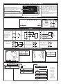
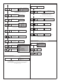
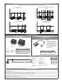
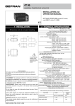
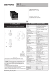
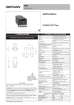
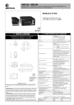
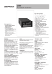
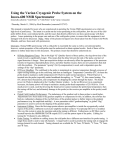
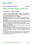
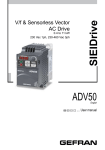
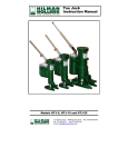
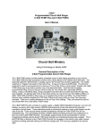
4T 72
UNIVERSAL TEMPERATURE INDICATOR
USER’S MANUAL
SOFTWARE VERSION 1.0x / 2.0x
code 81606A / edition 0.5 - 05/04
2 • TECHNICAL SPECIFICATIONS
1 • INSTALLATION
• Dimensions and cut-out: Panel mounting
Display
2, 3, 4 digits, red, height 14 mm
Keys
3 mechanical keys (Raise, Lower, F)
Accuracy
0.2% f.s. at 25°C ambient temperature, ts=120msec
Resolution
(function of settable sample time)
120msec, >13bit - 8000 points
60msec, >13bit - 8000 points (only for linear inputs)
30msec, >12bit - 4000 points (only for linear inputs)
15msec, >11bit - 2000 points (only for linear inputs)
Main input
TC, RTD, PTC, NTC
60 mV, 1 V, 5 V, 10 V, Ri ≥ 500KΩ
20 mA, Ri = 50Ω
adjustable digital filter
76
83
72
J, K, R, S, T, B, E, N
(IEC 584-1, CEI EN 60584-1, 60584-2)
36
Thermocouples
43
L GOST, U, G, D, C
Custom linearization available on request
30
69,5
Cold junction error
0,1° / °C
RTD type (scale configurable within indicated
range, with or without decimal point)
DIN 43760 (PT100), JPT100
Max. RTD line resistance
20Ω
PTC type / NTC type
990Ω, 25°C / 1KΩ, 25°C
Max. non-linearity error
See t.P parameter at page 3
°C / °F selection
Faceplate configurable
Linear scale ranges
-1999 to 9999 (with 4 digit display)
-999 to 999 (with 3 digit display)
-99 to 99 (with 2 digit display)
Configurable decimal point position, possible 32
segment linearization
(option) Power supply for 2wire transmitter
18V ±10%, 30 mA
1.2 V DC for potentiometer > 100 Ω (version P77)
Power supply (switching)
11...27 V DC, 18...27VAC ±10%,
50/60Hz, 3VA (not isolated)
Faceplate protection
IP65
Working / Storage temperatures
0...50°C / -20...70°C
Relative humidity
20 to 85%, non-condensing
54
8
!
For correct and safe
installation, follow the
instructions and
observe the warnings
contained in this
manual.
Installation
Panel mounting
Weight
90g for the complete version
Panel mounting:
Fix the device with the bracket provided before making any electrical connections.
To mount two or more devices side by side, use the cut-out dimensions shown above.
CE MARKING: EMC (electromagnetic compatibility) conformity to EEC Directive
89/336/CEE with reference to the generic Standard EN61000-6-2 (immunity in
industrial environments) and EN50081-1 (emission in residential environments).
BT (low voltage) conformity to Directive 73/23/CEE as modified by Directive 93/68.
MAINTENANCE: Repairs must be done out only by trained and specialized personnel.
Cut power to the device before accessing internal parts.
Do not clean the case with hydrocarbon-based solvents (Petrol, Trichlorethylene, etc.).
Use of these solvents can reduce the mechanical reliability of the device. Use a cloth
dampened in ethyl alcohol or water to clean the external plastic case.
SERVICE: GEFRAN has a service department. The warranty excludes defects caused
by any use not conforming to these instructions.
EMC conformity has been tested with the following connections
FUNCTION
TC input probe
“PT100” input probe
Power supply cable
8
CABLE
0,8 mm2 compensated
1 mm2
1 mm2
LENGTH USED
5 mt
3 mt
1 mt
3 • DESCRIPTION OF FRONT PANEL
“Raise” and “Lower” keys:
These keys are used for any operation that requires
a numerical parameter to be raised or lowered. ••
The speed of change is proportional to the time the
key is pressed. •• The operation is not cyclic: once
the maximum (minimum) limit is reached, there will
be no further increase (decrease) of the value, even
if the key remains pressed.
The keys can be configured to perform reset, hold,
display of the peak value, etc. as determined by the
‘t.U.’ and ‘t.d.’ parameters on the ‘In’ menu.
PV display: Indication of process variable
Indication of ‘HI’ or ‘Lo’ out of range •• Indication of
open circuit (br) or short circuit (Er) •• Display of
configuration and calibration messages
Label with engineering unit
Function key:
Gives access to different configuration stages •• Confirms
any parameter changes
4 • CONNECTIONS
• Power supply
5
1
2
3
6
7
8
9
10
!
Standard:
4
11
11...27Vdc ±10%
18...27Vac ±10%
12
~
11
PWR
50/60Hz, 3VA max.
not isolated
~
12
• Inputs
• Thermocouples
Available thermocouples:
J, K, R, S, T, B, E, N,
L, U, G, D, C
- Respect polarities
- For extensions, use
compensated cable
appropriate for
thermocouple.
• Linear input for potentiometer
• Linear input with 2-wire transmitter
4
+
3
-
-
2
4...20mA
4
Ri = 50Ω
2
1
+
3
-
2
+
• Pt100 / PTC / NTC
• Linear (V)
• Linear (I)
dc voltage linear input
3
dc current
linear input
2
20mA, Ri = 50Ω
1
R >100Ω
+ 1,2V
1
1
Use wires of adequate
thickness (min. 1mm2)
PT100, JPT100,
PTC, NTC
-
T
4
60mV, 1V, 5V, 10V,
Ri ≥ 500KΩ
2
T
(signal must be isolated
from power supply)
2-wire PTC /
NTC / Pt100
-
(signal must be isolated
from power supply)
1
3-wire Pt100
+
2
-
1
+
• Device structure: identification of boards
PROBE POWER board
CPU board
RTD, PTC, NTC Transmitter and
input
potentiometer
power supply
S3
ON
OFF
S4
OFF
ON
S1
S3
Probe power supply
Voltage
Jumpers
1V
S4 - S6B - S7A
24V (18V)
S6B - S7A
S4
S3
S9
S4
S5
S7
S8
S6
5 • PROGRAMMING and CONFIGURATION
LEVEL 1 DISPLAY
P.V.
Process variable
F
Pressed for
approx. 2 sec.
PA
IF
Information display
In
Input settings
Password
PA = 99
NO
YES
9
Keep the F key
pressed to browse
the menus.
Release the F key
to enter the
displayed menu.
Pr
Protection code
Ln
Custom linearization
Press the F key to
access the
parameters.
U.C.
User calibration
Keep the F key
pressed to exit any
menu at any time.
• Information display
IF
Information display
Software version
Display the type of CPU board
(thermocouples/linear)
• TC/LIN input parameters
In
Input settings
Type
Type
PROBE
4 DIGIT
without dec. point
Type of probe,
signal and scale of
main input
0
1
2
3
4
5
6
7
8
9
10
11
12
13
14
15
16
17
18
19
20
21
22
23
24
25
26
27
28
29
30
31
32
33
34
35
36
37
38
39
40
41
42
43
44
45
46
47
48
49
50
51
52
53
54
55
56
57
58
Probe: TC
TC J °C
0/1000
TC J °F
32/1832
TC K °C
0/1300
TC K °F
32/2372
TC R °C
0/1750
TC R °F
32/3182
TC S °C
0/1750
TC S °F
32/3182
TC T °C
-200/400
TC T °F
-328/752
TC B °C
44/1800
TC B °F
111/3272
TC E °C
-100/750
TC E °F
-148/1382
TC N °C
0/1300
TC N °F
32/2372
TC L °C
0/600
TC L °F
32/1112
TC U °C
-200/400
TC U °F
-328/752
TC G °C
0/2300
TC G °F
32/4172
TC D °C
0/2300
TC D °F
32/4172
TC C °C
0/2300
TC C °F
32/4172
TC °C
Custom
TC °F
Custom
Probe: RTD
PT100 °C
-200/600
PT100 °F
-328/1112
JPT100 °C
-200/600
JPT100 °F
-328/1112
Probe: PTC - NTC
PTC °C
-55/120
PTC °F
-67/248
NTC °C
-10/70
NTC °F
14/158
Probe: Voltage + Current
0...60mV
-1999/9999
0...60mV
custom linear
12...60mV
-1999/9999
12...60mV
custom linear
0...20mA
-1999/9999
0...20mA
custom linear
4...20mA
-1999/9999
4...20mA
custom linear
0...10V
-1999/9999
0...10V
custom linear
2...10V
-1999/9999
2...10V
custom linear
0...5V
-1999/9999
0...5V
custom linear
1...5V
-1999/9999
1...5V
custom linear
0...1V
-1999/9999
0...1V
custom linear
200mV...1V
-1999/9999
200mV...1V
custom linear
Probe: Custom PT100 - PTC - NTC
PT100
custom
JPT
PTC
custom
NTC
custom
3 DIGIT + sign
2 DIGIT + sign
with dec. point
without dec. point
with dec. point
without dec. point
with dec. point
0.0/999.9
32.0/999.9
0.0/999.9
32.0/999.9
0.0/999.9
32.0/999.9
0.0/999.9
32.0/999.9
-199.9/400.0
-199.9/752.0
44.0/999.9
111.0/999.9
-100.0/750.0
-148.0/999.9
0.0/999.9
32.0/999.9
0.0/600.0
32.0/999.9
-199.9/400.0
-199.9/752.0
0.0/999.9
32.0/999.9
0.0/999.9
32.0/999.9
0.0/999.9
32.0/999.9
Custom
Custom
0/999
32/999
0/999
32/999
0/999
32/999
0/999
32/999
-200/400
-328/752
not available
not available
-100/750
-148/999
0/999
32/999
0/600
32/999
-200/400
-328/752
0/999
32/999
0/999
32/999
0/999
32/999
Custom
Custom
0.0/99.9
32.0/99.9
0.0/99.9
32.0/99.9
0.0/99.9
32.0/99.9
0.0/99.9
32.0/99.9
-99.9/99.9
-99.9/99.9
not available
not available
not available
not available
not available
not available
0.0/99.9
32.0/99.9
-99.9/99.9
-99.9/99.9
not available
not available
not available
not available
not available
not available
Custom
Custom
0/99
32/99
0/99
32/99
0/99
32/99
0/99
32/99
-99/99
-99/99
not available
not available
not available
not available
non dsip.
not available
0/99
32/99
-99/99
-99/99
not available
not available
not available
not available
not available
not available
Custom
Custom
not available
not available
not available
not available
not available
not available
not available
not available
not available
not available
not available
not available
not available
not available
not available
not available
not available
not available
not available
not available
not available
not available
not available
not available
not available
not available
not available
not available
-199.9/600.0
-199.9/999.9
-199.9/600.0
-199.9/999.9
-200/600
-328/999
-200/600
-328/999
-99.9/99.9
-99.9/99.9
-99.9/99.9
-99.9/99.9
-99/99
-99/99
-99/99
-99/99
not available
not available
not available
not available
-55.0/120.0
-67.0/248.0
-10.0/70.0
14.0/158.0
-55/120
-67/248
-10/70
14/158
-55.0/99.9
-67.0/99.9
-10.0/70.0
14.0/99.9
-55/99
-67/99
-10/70
14/99
not available
not available
not available
not available
-199.9/999.9
custom linear
-199.9/999.9
custom linear
-199.9/999.9
custom linear
-199.9/999.9
custom linear
-199.9/999.9
custom linear
-199.9/999.9
custom linear
-199.9/999.9
custom linear
-199.9/999.9
custom linear
-199.9/999.9
custom linear
-199.9/999.9
custom linear
-999/999
custom linear
-999/999
custom linear
-999/999
custom linear
-999/999
custom linear
-999/999
custom linear
-999/999
custom linear
-999/999
custom linear
-999/999
custom linear
-999/999
custom linear
-999/999
custom linear
-99.9/99.9
custom linear
-99.9/99.9
custom linear
-99.9/99.9
custom linear
-99.9/99.9
custom linear
-99.9/99.9
custom linear
-99.9/99.9
custom linear
-99.9/99.9
custom linear
-99.9/99.9
custom linear
-99.9/99.9
custom linear
-99.9/99.9
custom linear
-99/99
custom linear
-99/99
custom linear
-99/99
custom linear
-99/99
custom linear
-99/99
custom linear
-99/99
custom linear
-99/99
custom linear
-99/99
custom linear
-99/99
custom linear
-99/99
custom linear
-9.9/9.9
custom linear
-9.9/9.9
custom linear
-9.9/9.9
custom linear
-9.9/9.9
custom linear
-9.9/9.9
custom linear
-9.9/9.9
custom linear
custom
custom
custom
custom
custom
custom
custom
custom
custom
custom
custom
custom
custom
custom
custom
custom linear
-9.9/9.9
custom linear
-9.9/9.9
custom linear
-9.9/9.9
custom linear
In case of non-availability, maximum and minimum limits are set to 0.
In case of custom linearization, test limits for setting LO and HI errors are given by the calibration values.
If these limits are not exceeded, they are taken into consideration as limits LO_S and HI_S.
Max. non-linearity error for
thermocouples (TC),
resistors (PT100) and
thermistors (PTC, NTC).
S, R
T
B
U
G
D
C
range 0...1750°C; error < 0.2% f.s. (t > 300°C) / for other range; error < 0.5% f.s.
error < 0.2% f.s. (t > -150°C)
range 44...1800°C; error < 0.5% f.s. (t > 300°C) / range 44,0...999,9; error < 1% f.s. (t > 300°C)
range -99,9...99,9 and -99...99°C; error < 0.5% f.s. / for other range; error < 0.2% f.s. (t > -150°C)
error < 0.2% f.s. (t > 300°C)
error < 0.2% f.s. (t > 200°C)
range 0...2300; error < 0.2% f.s. / for other range; error < 0.5% f.s.
The error is calculated as deviation from
NTC error < 0.5% f.s.
theoretical value and is expressed as
percentage of full scale (in °C).
Tc: J, K, E, N, L
error < 0.2% f.s.
PT100, JPT100 and PTC error < 0.2% f.s.
10
• Custom Linearization
Ln
0
1
2
3
Select sampling time
(resolution).
For linear input only.
120ms
60ms
30ms
15ms
Custom Linearization
of main input
> 13bit; 8000 divs
> 13bit; 8000 divs
> 12bit; 4000 divs
> 11bit; 2000 divs
Step 0
(beginning of scale value)
+4 to disable filter
(average of the last eight values sampled)
Display limits
(-1999 to 9999 for 4 digit display)
the n step value corresponds to input:
Digital filter on
main input
0.0 to 20.0 sec
Digital filter on process
variable display
0.0 ... 9.9
scale points
dP
0
1
2*
3*
Decimal point position for
main input scale
.......
mV beginning scale + n * ∆mV
∆mV = (mV full scale - mV beginning scale) / 32
Step 32
(full scale value)
Format
XXXX
XXX.X
XX.XX
X.XXX
Display limits
(-1999 to 9999 for 4 digit display)
Step 33
mV beginning
of scale
(*)
Step 34
mV full scale
(*)
Step 35
mV at 50°C
(*)
(*) not available for TC, RTD, PTC and NTC scales
min…max scale
of input selected in t.P
Minimum limit of main
input scale
min…max scale
of input selected in t.P
Maximum limit of main
input scale
Offset correction
of main input
(*) only for CPU, TC_LIN and tP = TC CUSTOM
• User Calibration
-999 to 999
scale points
U. C.
t. u. - t. d.
Raise key function
(active only in
P.V.selection)
Lower key function
(active only in
P.V.selection)
0
1
2
3
4
5
6
7
8
None
Zero
Hold
Flash
Max. peak display
Min. peak display
Delta peak display
Peak memory reset
Zero + peak memory reset
U.C.
CPU T Function
2
Custom RTD sensor
3
Custom PTC sensor
4
Custom NTC sensor
5
Potentiometer (0...1V)
Calibration of
minimum (*)
Calibration of
maximum (*)
• Protection
Pr
Protection code
Value
0
Display and setting of all
parameters
+4 to disable In pages
+16 to enable maintenance of reset latch at power-off (for linear inputs only)
+32 base configuration (the following parameters will not be displayed:
In: Ft, Fd, Of, L_L, H_L
11
• Filter - outputs with reference to parameters F.0 and r.A
The diagrams refer to a normal absolute alarm with hysteresis H = 0
F.0 = 2
DBI = Delay in turning on output after output is
turned off
F.0 = 1
DON = Delayed activation
Alarm
setpoint
Alarm
setpoint
Variable
Variable
Output
Output
Alarm
Alarm
rA
rA
rA
time
t < rA
time
t > rA
t < rA
F.0 = 3
DOF = Delayed deactivation
F.0 = 4
DP0 = Delayed activation
only at power-on
Alarm
setpoint
Alarm
setpoint
Variable
Variable
Output
Output
Alarm
Alarm
rA
rA
rA
rA
time
time
7 • ACCESSORIES
• Transformer
TRAFO 1
• RS323 interface cable for
configuration
N.B.:
the PC configuration
cable is supplied with the
programming software.
Make the connection with
the device powered and
with inputs and outputs
disconnected.
TRAFO 5
• ORDER CODE
Size
TRAFO 1:
L: 44,5mm,
B: 46,2mm,
H: 32,5mm
TRAFO 5:
L: 51,5mm,
B: 52,5mm,
H: 35mm
TRAFO 1
3VA, 230/24Vac transformer
TRAFO 5
10VA, 230/24Vac transformer
• ORDER CODE
WSK-0-0-0
Conform to VDE 0551, EN 60742, CE
Interface cables
+ CD Winstrum
• PTC / NTC
TECHNICAL DATA
Ø 7 ±0,5
25 ±1
5,50m
Mod. probe:
Cap material:
Temperature range:
PTC:
Response time:
Isolation:
Wire material:
Wire length:
Ambient probe
Plastic (Ø 7 x 25mm)
-20...80°C
R 25°C = 1KΩ ±1%
(KTY 81-110)
20sec (in still air)
100MΩ, 500Vdc
between cap and terminals
Unipolar in PVC (12/0,18)
5,50m
• ORDER
CODE
PTC 7 x 25 5m
NTC
• Installation notes
Always power the devices by means of the TRAFO1 transformers specified in the manual (one for each device) when:
• The application is unknown.
• Multiple devices have input signals that are not isolated from one another, such as, for example: non-isolated grounded thermocouples, transducers or transmitters
powered by a single supply, linear inputs with voltage or current not isolated from one another.
• It is a general rule that devices with shared signals (probes, transmitters, signal retransmission, etc.) must be powered by a separate transformer for each device.
• Any special cases not covered by the above example must be evaluated from time to time.
• One possible example of a power supply by a single transformer is the case of devices with RTD or PTC probes, with relay or logic outputs connected to individually
isolated devices (such as GTS static groups).
ATTENTION: in case of an input with a NON-isolated grounded thermocouple, the secondary of the power transformer for the device CANNOT be grounded: doing so
will cause the device to fail, with probable blowing of the internal fuse.
12
ORDER CODE
4T
72
9
N° Digits
Power supply
2 + sign
2
3 + sign
3
4
4
9
11 to 27VDC, 18…27 VAC not isolated
Sensor power supply
None
00
(alternative to RTD, PTC, NTC)
1.2VDC for potentiometer (*)
01
18Vdc, 50 mA
for 2-wire transmitter
24
(*) For input from potentiometer, request version P77
(R input > 10MΩ)
Kindly contact GEFRAN for information on available codes.
• WARNINGS
!
WARNING: this symbol indicates danger.
It is seen near the power supply circuit and near high-voltage relay contacts.
Read the following warnings before installing, connecting or using the device:
• follow instructions precisely when connecting the device.
• always use cables that are suitable for the voltage and current levels indicated in the technical specifications.
• the device has no ON/OFF switch: it switches on immediately when power is turned on. For safety reasons, devices permanently connected to the power
supply require a two-phase disconnecting switch with proper marking. Such switch must be located near the device and must be easily reachable by the
user. A single switch can control several units.
• if the device is connected to electrically NON-ISOLATED equipment (e.g. thermocouples), a grounding wire must be applied to assure that this
connection is not made directly through the machine structure.
• if the device is used in applications where there is risk of injury to persons and/or damage to machines or materials, it MUST be used with auxiliary alarm
units. You should be able to check the correct operation of such units during normal operation of the device.
• before using the device, the user must check that all device parameters are correctly set in order to avoid injury to persons and/or damage to property.
• the device must NOT be used in inflammable or explosive environments. It may be connected to units operating in such environments only by means of
suitable interfaces in conformity to local safety regulations.
• the device contains components that are sensitive to static electrical discharges. Therefore, take appropriate precautions when handling electronic circuit
boards in order to prevent permanent damage to these components.
Installation: installation category II, pollution level 2, double isolation
• power supply lines must be separated from device input and output lines; always check that the supply voltage matches the voltage indicated on the
device label.
• install the instrumentation separately from the relays and power switching devices
• do not install high-power remote switches, contactors, relays, thyristor power units (particularly if “phase angle” type), motors, etc... in the same cabinet.
• avoid dust, humidity, corrosive gases and heat sources.
• do not close the ventilation holes; working temperature must be in the range of 0...50°C.
If the device has faston terminals, they must be protected and isolated; if the device has screw terminals, wires should be attached at least in pairs.
• Power: supplied from a disconnecting switch with fuse for the device section; path of wires from switch to devices should be as straight as possible; the
same supply should not be used to power relays, contactors, solenoid valves, etc.; if the voltage waveform is strongly distorted by thyristor switching units
or by electric motors, it is recommended that an isolation transformer be used only for the devices, connecting the screen to ground; it is important for the
electrical system to have a good ground connection; voltage between neutral and ground must not exceed 1V and resistance must be less than 6Ohm; if
the supply voltage is highly variable, use a voltage stabilizer for the device; use line filters in the vicinity of high frequency generators or arc welders;
power supply lines must be separated from device input and output lines; always check that the supply voltage matches the voltage indicated on the
device label.
• Input and output connections: external connected circuits must have double insulation; to connect analog inputs (TC, RTD) you have to: physically
separate input wiring from power supply wiring, from output wiring, and from power connections; use twisted and screened cables, with screen connected
to ground at only one point; to connect adjustment and alarm outputs (contactors, solenoid valves, motors, fans, etc.), install RC groups (resistor and
capacitor in series) in parallel with inductive loads that work in AC (Note: all capacitors must conform to VDE standards (class x2) and support at least 220
VAC. Resistors must be at least 2W); fit a 1N4007 diode in parallel with the coil of inductive loads that operate in DC.
GEFRAN spa will not be held liable for any injury to persons and/or damage to property deriving from tampering, from any incorrect or
erroneous use, or from any use not conforming to the device specifications.
13