1
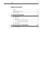
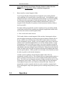
Faraday Isolator
Low Power ISO Series User’s Manual
ii
Preface
Warranty
Newport Corporation warrants that this product will be free from defects in
material and workmanship and will comply with Newport’s published
specifications at the time of sale for a period of one year from date of
shipment. If found to be defective during the warranty period, the product
will either be repaired or replaced at Newport's option.
To exercise this warranty, write or call your local Newport office or
representative, or contact Newport headquarters in Irvine, California. You
will be given prompt assistance and return instructions. Send the product,
freight prepaid, to the indicated service facility. Repairs will be made and the
instrument returned freight prepaid. Repaired products are warranted for the
remainder of the original warranty period or 90 days, whichever is longer.
Limitation of Warranty
The above warranties do not apply to products which have been repaired or
modified without Newport’s written approval, or products subjected to
unusual physical, thermal or electrical stress, improper installation, misuse,
abuse, accident or negligence in use, storage, transportation or handling. This
warranty also does not apply to fuses, batteries, or damage from battery
leakage.
THIS WARRANTY IS IN LIEU OF ALL OTHER WARRANTIES,
EXPRESSED OR IMPLIED, INCLUDING ANY IMPLIED WARRANTY
OF MERCHANTABILITY OR FITNESS FOR A PARTICULAR USE.
NEWPORT CORPORATION SHALL NOT BE LIABLE FOR ANY
INDIRECT, SPECIAL, OR CONSEQUENTIAL DAMAGES RESULTING
FROM THE PURCHASE OR USE OF ITS PRODUCTS.
First printing 2005
© 2005 by Newport Corporation, Irvine, CA. All rights reserved. No part of
this manual may be reproduced or copied without the prior written approval
of Newport Corporation.
This manual has been provided for information only and product
specifications are subject to change without notice. Any change will be
reflected in future printings.
Newport Corporation
1791 Deere Avenue
Irvine, CA, 92606 USA
P/N 44757-01 Rev. A
Preface
iii
Technical Support Contacts
North America & Asia
Europe
Newport Corporation Service Dept.
Newport/MICRO-CONTROLE S.A.
1791 Deere Ave. Irvine, CA 92606
Zone Industrielle
Telephone: (949) 253-1694
45340 Beaune la Rolande, FRANCE
Telephone: (800) 222-6440 x31694
Telephone: (33) 02 38 40 51 56
Asia
Newport Opto-Electronics
Technologies
253 Aidu Road, Bld #3, Flr 3, Sec C,
Shanghai 200131, China
Telephone: +86-21-5046 2300
Fax: +86-21-5046 2323
Newport Corporation Calling Procedure
If there are any defects in material or workmanship or a failure to meet
specifications, promptly notify Newport's Returns Department by calling
1-800-222-6440 or by visiting our website at www.newport.com/returns within the
warranty period to obtain a Return Material Authorization Number (RMA#).
Return the product to Newport Corporation, freight prepaid, clearly marked with the
RMA# and we will either repair or replace it at our discretion. Newport is not
responsible for damage occurring in transit and is not obligated to accept products
returned without an RMA#.
E-mail: [email protected]
When calling Newport Corporation, please provide the customer care representative
with the following information:
•
•
•
Your Contact Information
Serial number or original order number
Description of problem (i.e., hardware or software)
To help our Technical Support Representatives diagnose your problem, please note
the following conditions:
•
•
•
•
•
Is the system used for manufacturing or research and development?
What was the state of the system right before the problem?
Have you seen this problem before? If so, how often?
Can the system continue to operate with this problem? Or is the system nonoperational?
Can you identify anything that was different before this problem occurred?
iv
Preface
Table of Contents
Warranty................................................................................................. ii
Technical Support Contacts .................................................................. iii
Table of Contents .................................................................................. iv
1 General Information
1.1
1.2
1.3
1.4
Introduction ...................................................................................1
Safety.............................................................................................2
Operation .......................................................................................3
1.3.1 Using your Faraday Isolator ..............................................6
1.3.2 Tuning your Faraday Isolator ............................................7
Specifications ................................................................................8
2 Factory Service Information
2.1
1
11
Service Form ...............................................................................11
1
General Information
1.1
Introduction
Newport’s Faraday Isolators are essentially a uni-directional light valve. They are used
to protect a laser source from destabilizing feedback or actual damage from backreflected light. Figure 1 below identifies the main elements of your Faraday Isolator.
Figure 1: Newport’s 650-980 nm Low Power Faraday Isolator
Base Clamp
With Screw
Serial
Input
Polarizer
Model
Designation
Magnet
Housing
Transmission
Direction
Output
Polarizer
Baseplate
The Faraday Isolator is a cylindrically shaped magneto-optic device. Strong Neodymium
Iron Boron permanent magnets are used to generate high (>10,000 Gauss) axially
oriented fields within the magnet housing. The strong longitudinal field causes 45
degrees of non-reciprocal polarization rotation for propagating light via the Faraday
Effect in the terbium gallium garnet (“TGG”) crystal located within the magnet housing.
In operation, the magnet housing is sandwiched between input and output polarizers that
have their transmission axes oriented 45 degrees relative to each other to account for the
45 degrees of Faraday Rotation in the TGG crystal in the forward (transmission)
direction. In the reverse (isolation) direction, the non-reciprocal Faraday rotation and the
1
2
Free Service Information
45 degree polarizer transmission axis angle add so that the polarization transmitted by the
output polarizer is rejected at the input polarizer.
Your Newport Faraday Isolator is labeled with a serial number on the base clamp of the
device.
1.2
Safety
The operational hazards presented to operating personnel by the use of your Newport
Faraday Isolator are listed below. An explanation of how the Faraday Isolator is
designed, together with procedures users can employ to eliminate or minimize these
hazards is presented in italics.
1.
Danger of sharp ferromagnetic objects being attracted to the residual
permanent magnetic fields outside of the Faraday Isolator.
Your Newport Faraday Isolator requires strong internal magnetic fields to
operate properly. Efforts have been made to minimize external fields from the
device while still maintaining a relatively small and cost effective package. The
external fields are designed to be well within Federal safety guidelines which
limit external fields from magnetic devices to be less than 2KGauss at a radial
distance of 5cm from the outside of the device. However, such fields can be
sufficient to attract nearby objects such as knives and razor blades. Should
attraction of such objects begin to occur there would be a strong attractive force
directing these objects towards the interior of the magnet housing. This could be
particularly likely to result in injury (e.g. a cut or puncture wound) if such
attraction occurred while the device was being handled –particularly if a body
part of the operating personnel is near a beam Aperture (i.e. end) of the device.
To minimize the above risks remove all loose ferromagnetic objects from the
path over which your Newport Faraday Isolator is to be moved prior to
attempting to move it. Do not pick up the isolator by its ends (i.e. apertures)
where the attractive magnetic fields are strongest. Always pick the isolator up
along its sides.
2.
Failure of operating personnel to observe standard laser safety by sighting
down through the Faraday Rotator when laser radiation is present.
The optical elements within the Newport Faraday Isolators can be transmissive
throughout the visible and near infrared. Consequently it is never appropriate to
view through the device in either the transmission or isolation direction when
laser radiation is present –even with laser safety goggles.
General Information
3
Never sight through your Newport Faraday Isolator in either direction
when there is any possibility of laser radiation being present.
3.
Harm caused by external magnetic fields.
Your Newport Faraday Isolator has been designed to meet existing Federal
safety guidelines for external fields as noted previously. Such guidelines could
change in the future as more information becomes known or reviewed regarding
the interaction between magnetic fields and human health. Since there exist
various claims regarding the potential harmful (and beneficial!) effects of
magnetic fields on humans it is prudent to limit interaction with these fields as
much as possible.
Personnel with any magnetically sensitive implants such as pacemakers should
consult their medical doctor regarding any potential complications which could
arise from the isolator external magnetic fields.
4. Other non-health related hazards.
The Faraday Isolator external magnetic fields can draw ferromagnetic objects
into the magnet housing that can damage the optical elements within the device.
Keep a suitable area in all directions around the Faraday Isolator clear of any
loose ferromagnetic objects. Ideally, use non-magnetic tools (such as 300 series
stainless steel or titanium) and hardware to secure the Faraday Isolator. If only
ferromagnetic tools are available use extreme care when using them around the
Faraday Isolator. It is always helpful to bring such tools towards an aperture (or
end) radially rather than along the optical beam path. Doing this ensures that the
fields will tend to pull such objects into the magnet housing endplate rather than
into the optical aperture. Where possible use two hands, one to hold the tool and
the other to guide it to the desired destination.
Another concern regarding external magnetic fields is their effect on
magnetically sensitive devices. The external fields are strong enough to induce a
pulse of current in electronic devices (such as digital watches) that can destroy
them. The fields can also disrupt the operation of other mechanical devices with
ferromagnetic parts in them. Finally, the external fields can erase information
from magnetic strips such as are found on credit and ID cards. Remove all
magnetically sensitive materials and devices such as watches, computer hard
drives and magnetic strips from operators prior to working in the proximity of an
isolator.
1.3
Operation
4
Free Service Information
Figure 2: View of Faraday Isolator and Tuning Features.
Base Clamp
With Screw Adjustment
Polarization
Transmission Axis
Indicator, Located on
Input Polarizer Mount.
and
Location of Set Screw
for Adjusting
Waveplate
Input Polarization
Axis Indicators
H, 45, V
Waveplate Holder
and Input
Aperture
Note output
polarization is at
45 deg.
Note input
polarization is
vertical.
The low power Faraday Isolator uses dichroic sheet polarizers at both the input and output of the
device. These broadband polarizers absorb the rejected transmission and are therefore only
effective for low power applications. The inscribed arrow on the baseclamp displays the
transmission direction. The output polarizer is seen to be oriented with its transmission axis
rotated 45 degrees relative to the input polarization. The input polarization shown is vertical.
The central magnet housing together with the TGG crystal residing in its center forms a Faraday
Rotator. The Faraday Rotator rotates the input transmission axis by 45 degrees so that
transmitted light has a polarization aligned with the output transmission axis. The input and
General Information
5
output polarizers work in conjunction with the central Faraday Rotator to form a Faraday
Isolator. Though the overall size of the device varies depending on the model, the operation of
the polarizer mounts are identical.
Figure 3: Horizontal Input Polarization
Figure 4: Vertical Input Polarization
Figure 3 shows a device aligned for a horizontal input polarization. The screw-hole located on
the side of the polarizer mount indicates the approximate angular position of the polarizer
transmission axis and maximum transmission is observed when the input polarization is aligned
to this angle, the default orientation is horizontal.
Figure 4 shows a device aligned for a vertical input polarization, with the transmission axis
rotated 90 degrees with respect to that depicted in Figure 3.
6
Free Service Information
y-axis=090
+z-axis = Direction of beam propagation
(Direction of Arrow on Device)
x-axis=000
Laser Source
1.3.1
Using your Faraday Isolator
Observe the guidelines for safe use of your Faraday Isolator found in Section 1.2 above when
removing your isolator from its shipping container. Do not remove the protective dust-cover
endcaps from the polarizers until the device is in a clean, relatively dust free environment. Save
the protective endcaps, packaging material and containers in the event that the device should
ever need to be returned to Newport.
Verify that the Input and Output polarization states are consistent with the intended mode of
operation. If not, re-adjust the isolator as required (see Section 1.3.2).
With the source laser off, or running at very low power (less than 100mW), position the Faraday
Isolator such that the source laser beam can be directed through the Input Aperture.
Critical alignment of the Faraday Isolator should be done at low power (less than 100mW) in
order to prevent optical damage to your isolator or laser source.
Use IR cards or viewers to ensure that the source laser beam is centered on the input and output
apertures. The clear aperture of this device is 4mm, centered on the circular cross section of the
magnet body. There are different mounting options for establishing appropriate beam height. It
is also preferable to use an IR viewer to ensure that weak reflections from AR coated optical
surfaces in the Faraday Isolator are not being directed back into the source laser. The optical
surfaces in the Faraday Isolator are angled slightly to reduce these reflections. Increasing the
General Information
7
distance between the Faraday Isolator and the source laser can also help ensure that no
reflections couple back into the source laser if necessary. Alternatively, if the beam used is
smaller than the aperture of the device by a reasonable margin, the device may be slightly tilted.
At this point, the Faraday Isolator should be secured to the work surface with two (2) ¼ - 20 or
M6 screws –one for each slot in the baseplate flanges. Alternatively, the baseplate may be
removed from the baseclamp by removing two 8-32 screws on the bottom side of the baseplate.
Then, the baseclamp/isolator assembly may be mounted to a standard laboratory post with an 832 set screw or may be conveniently mounted into laser systems, minimizing the required
footprint of the device. Steel (ferromagnetic) ball drivers or other such wrenches will be
attracted to the external magnetic field surrounding the device. If possible, use anti-magnetic
stainless steel or titanium tools. If ferromagnetic tools are used, it is desirable to introduce them
slowly towards the device from the sides along the direction of the baseplate flange slots.
One important consideration is that this isolator is intended to be used at low power. The device
is very compact given the physical size of the polarizers used in its construction. One drawback
of this is that the rejected power is absorbed in the polarizers themselves and therefore damage
thresholds are limited to 25W/cm2 CW.
1.3.2
Tuning your Faraday Isolator
A. Adjusting Input Polarization
The transmission axis of the input polarizer is indicated by the radial position of
the screw hole located on the input polarizer mount. If the linear polarization of the laser
source is geometrically known, aligning the input polarization of the Faraday Isolator to
that of the laser source is straightforward. Simply loosen the #2-56 socket head
Baseclamp Screw in the Baseclamp until the magnet housing rotates freely. Continue to
rotate the magnet housing until the Input Polarizer transmission axis is aligned to that of
your laser source. Following alignment procedures, rotating the magnet body inside the
clamp until maximum transmission is observed through the isolator will indicate that the
input polarization is parallel to the input polarizer axis. Then re-tighten the Baseplate
Clamp Screw.
B. Fine Wavelength Adjustment
Each of the 650, 780, 850, and 980 nm isolators may be tuned over the wavelength range
specified in section 1.4. Tuning is achieved by adjusting the relative angle between the
input and output polarizers. For wavelengths longer than the central wavelength, the
faraday rotation is less than 45 deg., for wavelengths shorter than the central wavelength,
the faraday rotation is more than 45 deg. and therefore, the device may be tuned for
maximum extinction with a small transmission loss, illustrated by the wavelength tuning
curves in section 1.4. The 3dB bandwidth of the isolators ranges from 12 nm at 650 nm
8
Free Service Information
to 20 nm at 980nm, in increasing value. For maximum extinction, manually tune the
device to the appropriate wavelength.
With the source laser operating at an average power of 100 mW or less (attenuate the
beam if necessary to achieve such a low power level) direct the source laser beam
through the Faraday Isolator in the reverse direction –through the Output Polarizer first
and then through the Input Polarizer. Use an IR viewer to view the transmitted radiation
to ensure that it is directed onto a Power Meter. The Power Meter should be sensitive
enough to detect power levels below 0.01mW (or 40dB of the input signal used). As a
reference, 40 dB is a factor of 1:10000 and 10dB is a factor of 1:10. If necessary, loosen
the Baseplate Clamp Screw to allow the Output Polarizer transmission axis to be rotated
parallel to the source laser polarization axis. Re-tighten this screw when complete.
Loosen the button head Input Polarizer Clamp Ring screws just enough so that the Input
Polarizer Mount may be rotated (the Input Polarizer is opposite to the laser source at this
point). Rotate the Input Polarizer Mount until a minimum reading is indicated on the
Power Meter. Re-tighten the Input Polarizer Clamp Ring Screws. The minimum reading
should be at least 30dB (1:1000) of the input signal. If not, call Newport for assistance
(see Section 2 below). The Faraday Isolator is now optimized to operate at the new laser
source operating wavelength. It may now be installed for operation in transmission with
the laser source as per Section 1.4 and the procedure outlined in Section 1.3.2 A.
C. Waveplate Option and Adjustment
It is possible to order a Faraday Isolator with a half-waveplate on the output. Should any
of the above adjustments become necessary, or if the desired output polarization changes,
the waveplate will need to be adjusted. To re-align the waveplate loosen the radially
oriented set-screw in the output polarizer mount and rotate the waveplate until the desired
output polarization is achieved. Re-tighten the waveplate set-screw. Do not overtighten. A waveplate may also be used in the input of the device if necessary.
1.4
Specifications
General Information
Model
ISO-04-980-LP
ISO-04-850-LP
ISO-04-780-LP
ISO-04-650-LP
9
Center
Wavelength
Tunable
Range
Isolation
Trans. (%)
CW Damage
Threshold
(nm)
980
850
780
650
(nm)
960-1030
840-960
740-840
630-700
(dB)
30-38
30-38
30-38
30-35
(see note 1)
>90
>88
>82
>75
W/cm2
25
25
25
25
Two-Stage Option
Faraday Isolators may be used in series to obtain 60+dB isolation,
mounted on a common baseplate.
Mounting Options
Magnet housings are inserted into a clamping device that provides
8-32 screw holes and may be mounted onto a standard post. All devices
include a base for mating with a standard English breadboard (1/4-20 screw holes on 1"
spacing).
Notes
1. Transmission: This is measured from the center wavelength. Tunable transmission will
be wavelength dependent. Please consult the spectra below.
2. Damage Threshold: Damage threshold is limited by cemented optics and broadband
AR coatings for wavelength tunability, for higher damage threshold applications, please
contact Newport.
3. Operating Temperature: Performance of Newport’s Faraday rotators/isolators is related
to operating temperature. For information on the effect of operating temperature on
Newport’s Faraday rotators/isolators, please review our technical bulletin, Effects of
Temperature on Newport’s Faraday Rotators/Isolators
4. Center Wavelength: This refers to the wavelength specified for 45 +/-2 deg and is not
necessarily the median of the wavelength range.
5. Tunable Transmission: The below graphs show the transmission of the device
following tuning as per instructions in section 1.3.2 B.
10
Free Service Information
500-1030nm LP Faraday Isolator Tunable Transmission by Model
Transmission (%)
100
95
90
980nm
850nm
780nm
650nm
85
80
75
70
630
680
730
780
830
880
Wavelength (nm)
930
980
1030
2
Factory Service Information
2.1
Service Form
Newport Corporation
U.S.A. Office: 800-222-6440
FAX: 949/253-1479
Name_________________________________
Return Authorization # _________________________
(Please obtain RA# prior to return of item)
Company ___________________________________________________________________________
Address ______________________________
Date _______________________________________
Country _______________________________
Phone Number _______________________________
P.O. Number ___________________________
FAX Number_________________________________
Item(s) Being Returned:
Model # ______________________________
Serial # _____________________________________
Description __________________________________________________________________________
___________________________________________________________________________________
___________________________________________________________________________________
___________________________________________________________________________________
___________________________________________________________________________________
___________________________________________________________________________________
Reason for return of goods (please list any specific problems):
___________________________________________________________________________________
___________________________________________________________________________________
___________________________________________________________________________________
___________________________________________________________________________________
___________________________________________________________________________________
___________________________________________________________________________________
___________________________________________________________________________________
___________________________________________________________________________________
___________________________________________________________________________________
11
12
Free Service Information
Notes:______________________________________________________________________________
___________________________________________________________________________________
___________________________________________________________________________________
___________________________________________________________________________________
___________________________________________________________________________________
___________________________________________________________________________________
___________________________________________________________________________________
___________________________________________________________________________________
___________________________________________________________________________________
___________________________________________________________________________________
___________________________________________________________________________________
___________________________________________________________________________________
___________________________________________________________________________________
___________________________________________________________________________________
___________________________________________________________________________________
___________________________________________________________________________________
___________________________________________________________________________________
___________________________________________________________________________________
___________________________________________________________________________________
___________________________________________________________________________________
___________________________________________________________________________________
___________________________________________________________________________________
___________________________________________________________________________________
___________________________________________________________________________________
___________________________________________________________________________________
___________________________________________________________________________________
___________________________________________________________________________________
___________________________________________________________________________________
___________________________________________________________________________________
___________________________________________________________________________________
___________________________________________________________________________________
___________________________________________________________________________________
___________________________________________________________________________________
___________________________________________________________________________________
___________________________________________________________________________________
___________________________________________________________________________________
___________________________________________________________________________________
___________________________________________________________________________________