1
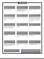
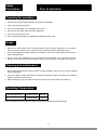
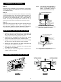
User's MANUAL Before using the unit, read this user’s manual carefully which provides important information concerning the proper operation of the unit. Dear Customer, Congratulations! Thank you for buying this KORYO appliance. Your new Window Air Conditioner has been designed for your convenience. We are sure you will get many years of trouble free service from this appliance. Before commissioning this device please read this user manual carefully. Please retain this user manual, warranty certificate, sales receipt and if possible carton with the inner packaging. CONTENTS Safety Precautions............................................................................................................................................4 Unit Parts Identification.....................................................................................................................................7 Operating Instructions.......................................................................................................................................8 Installation Instructions......................................................................................................................................13 Troubleshooting.................................................................................................................................................16 Do’s & Don’ts.....................................................................................................................................................17 E-Waste Disposal..............................................................................................................................................17 Terms and Conditions........................................................................................................................................18 Warranty Card...................................................................................................................................................19 2 Read This Manual Inside you will find many helpful hints on how to use and maintain your air conditioner properly. Just a little preventive care on your part can save you a great deal of time and money over the life of your air conditioner. You’ll find many answers to common problems in the chart of troubleshooting tips. CAUTION • Contact the Koryo authorised service technician for repair or maintenance of this unit. • Contact the Koryo authorized service engineer for the installation of this unit. • The air conditioner is not intended for use by young children or any mentally unstable person without supervision. • Young children should be supervised to ensure that they do not play with the air conditioner. • If the power cord is to be replaced, replacement work shall be performed by Koryo authorized service personnel only. • Installation work must be performed in accordance with the national wiring standards by Koryo authorized service personnel only. 3 Safety Precautions To prevent injury to the user or other people and property damage, the following instructions must be followed. Incorrect operations due to ignoring the instructions may cause harm or damage. The seriousness is classified by the following indications. WARNING This symbol indicates the possibility of death or serious injury. CAUTION This symbol indicates the possibility of injury or damage to property. • Meanings of symbols used in this manual are as shown below. Never do this. ! Always do this. WARNING Do not modify power cord length or share the outlet with other appliances. •It may cause electric shock or fire due to heat generation. Always ensure effective earthing. •Incorrect earthing may cause electric shock. Unplug the unit if sound, smell, or smoke comes from it. •It may cause fire and electric shock. Keep fire arms away. •It may cause fire. Do not use the power cord near flammable gas or combustibles, such as gasoline, benzene, thinner, etc. •It may cause an explosion or fire. Do not operate with wet hands or in damp environment. •It may cause electric shock. Do not allow water to run into electric parts. •It may cause failure of machine or electric shock Do not use the socket if it is loose or damaged. •It may cause fire and electric shock. Do not use the power cord close to heating appliances. •It may cause fire and electric shock. Ventilate room before operating air conditioner if there is a gas leakage from another appliance. •It may cause explosion, fire and, burns. 4 Plug in power plug properly. •It may cause electric shock or fire. •If the power cord is damaged, it must be replaced by Koryo authorized service centre in order to avoid a hazard. Do not direct airflow at room occupants. •It could damage your health. Always install circuit breaker and a dedicated power circuit. •Incorrect installation may cause fire and electric shock. Do not open the unit during operation. •It may cause electric shock. Do not disassemble or modify unit. •It may cause failure and electric shock. CAUTION When the air filter is to be removed, do not touch the metal parts of the unit. • It may cause an injury. When the unit is to be cleaned, switch off, and turn off the circuit breaker. •Do not clean unit when power is on as it may cause fire and electric shock, it may cause an injury Stop operation and close the window in storm or hurricane. •Operation with windows opened may cause wetting of indoor and soaking of household furniture. Do not place obstacles around air-inlets or inside of air-outlet. •It may cause failure of appliance or accident. Do not use strong detergent such as wax or thinner but use a soft cloth. •Appearance may be deteriorated due to change of product color or scratching of its surface. Do not clean the air conditioner with water. •Water may enter the unit and degrade the insulation. It may cause an electric shock. Do not put a pet or house plant where it will be exposed to direct air flow. •This could injure the pet or plant Hold the plug by the head of the power plug when taking it out. •It may cause electric shock and damage Ensure that the installation bracket of the outdoor appliance is not damaged due to prolonged exposure. •If bracket is damaged, there is concern of damage due to falling of unit. Do not place heavy object on the power cord and ensure that the cord is not compressed. •There is danger of fire or electric shock. Ventilate the room well when used together with a stove, etc. •An oxygen shortage may occur. Do not use for special purposes. •Do not use this air conditioner to preserve precision devices, food, pets, plants, and art objects. It may cause deterioration of quality, etc. Turn off the main power switch when not using the unit for a long time. •It may cause failure of product or fire. Always insert the filters securely. Clean filter once every two weeks •Operation without cause failure filters may Do not drink water drained from air conditioner. •It contains contaminants could make you sick. and If water enters the unit, turn the unit off at the power Do switch not disassemble or modify unit. Isolate outlet and off the circuit breaker. supply by taking the power plug out and contact Koryo authorized service centre. Use caution when unpacking and installing. Sharp edges could cause injury. 5 Safety Precautions Prior to Operation Preparing for operation 1. Contact a Koryo authorized installation specialist for installation. 2. Plug in the power plug properly. 3. Do not use a damaged or non-standard power cord. 4. Do not share the same outlet with other appliances. 5. Do not use an extension cord. 6. Do not start/stop operation by plugging/unplugging the power cord. Usage 1. Exposure to direct airflow for an extended period of time could be hazardous to your health. Do not expose occupants, pets, or plants to direct airflow for extended periods of time. 2. Due to the possibility of oxygen deficiency, ventilate the room when used together with stoves or other heating devices. 3. Do not use this air conditioner for non-specified special purposes (e.g. Preserving precision devices, food, pets, plants, and art objects). Usage in such a manner could harm such property. Cleaning and maintenance 1. Do not touch the metal parts of the unit when removing the filter. Injuries can occur when handling sharp metal edges. 2. Do not use water to clean inside the air conditioner. Exposure to water can destroy the insulation, leading to possible electric shock. 3. When cleaning the unit, first make sure that the power and circuit breaker are turned off. Operating Temperature Cooling Operation Outdoor temp: 18-43ºC Indoor temp: 17-32ºC Note: Performance may be reduced outside of these high operating temperature areas. 6 UNIT PARTS IDENTIFICATION 1. Front panel 2. Air filter 3. Frame 4. Cabinet 5. Air inlet grill (outdoor side) 6. Air outlet grill 7. Electronic control keypad 8. Power supply cord and plug 9. Remote control 1. Power cord conductors are distinguished according to color as follows (see Fig.1) 2. For your safety and protection, this unit is earthed through the power cord (see Fig.2) Please contact Koryo authorized service centre. 3. Be sure that the unit being correctly grounded. The wall outlet (Circuit break MCB switch) should be provided with reliable earth wire. 4. The unit should be provided with an individual circuit and the circuit breaker/fuse rating should be the same as that of the power cord and wall outlet. POWER CORD Wall outlet A Circuit break switch E N E-Earth wire, Yellow/Green N-Neutral wire, Blue Fig: 1 A-Active wire, Brown Fig: 2 7 OPERATING INSTRUCTIONS Controls The electronic control key will look like the following: C FAN TIMER SWING TEMP SWING SLEEP HIGH MED FAN DRY LOW COOL MODE POWER NOTE: The outline of the operation panel is based on typical model, the function is the same with your air conditioner while some difference may exist in appearance. Vent Control The vent control is located above the control knobs. The operation method is different on different models (see the following figures). For maximum cooling efficiency, CLOSE the vent. This will allow internal air circulation. OPEN the vent to discharge stale air. CLOSE VENT OPEN CLOSE OPEN To open the vent, pull the lever towards you To open the vent, set the lever to the right position To close it, push it in. To close it, set the lever in the left position. OPERATING INSTRUCTIONS POWER: Press the POWER key to turn the unit on/off. (The TIMER key controls the auto start / stop feature of the unit.) MODE: Press the “MODE” key to select the appropriate operating mode from COOLING, FAN and DRY.The green indicator light beside the “MODE” option will illuminate, identifying the mode selected. When using the DRY and AUTO mode, you cannot select a fan speed. The fan motor operates on LOW speed in DRY mode and on MED speed in AUTO mode. ▲TEMPERATURE SETTINGS UP: Press the ▲ key to increase the set (operating) temperature of the unit. Each time the key is pressed the temperature increases as follows: 1OC (Celsius Scale) Maximum Setting 31OC 8 ▼ TEMPERATURE SETTINGS DOWN: Press the ▼ key to decrease the set (operating) temperature of the unit. Each time the key is pressed the temperature decreases as follows: 1OC (Celsius Scale) Minimum Setting 16OC FAN: Press this key to activate the appropriate fan speed setting. Each depression of the key will alternate through LOW, MED, HIGH fan speed options. The green indicator light beside the FAN speed option will illuminate, identifying the fan speed selected. SWING (Select Mode): Press the “SWING” (only selected model) key to activate the automatic air swing (oscillation) feature. The green indicator light adjacent to the “SWING” key will illuminate, identifying to the selected mode is operational. The vertical louvers will oscillate back and forth (side to side) automatically sweeping air alternately for comfortable cooling . To stop the air swing feature, Press the “SWING” key again, the green indicator light adjacent to the key will go off. Press the “SWING” key for 2 seconds will activate the SLEEP mode which can reduce noise creating a comfortable sleeping environment. When the SLEEP mode is activated, the green indicator light beside the “SLEEP” function will illuminate. TIMER: Press the “TIMER” key to activate the “auto start/auto stop” timer function. Auto start/stop programs can be set from 0~12 hours. Each depression of the “TIMER” key will increase the selected time in 1 hour increments. DRY: This mode is used to decrease the humidity in the room. COOLING: The temperature setting are adjustable between 16OC to 31OC. Cooling begins automatically when the room temperature is 1OC above the set point, and stops when the room temperature is 1OC below the set point. The fan will not stop running. AUTO: The fan motor remains on MED speed in AUTO mode. The unit will select the appropriate operating mode from FAN, COOL based upon the temperature difference between the actual and desired room temperature. If the actual room temperature is 2OC above the set point, the unit operates in cooling mode. When the actual room temperature is not 2OC or higher above the set point and not 1OC or lower below the set point, the unit will select the FAN mode Note: If activating the SLEEP mode when the unit is operating on AUTO mode, the fan motor will changed into LOW speed mode immediately. SLEEP: Press and hold the “SWING” key for 2 seconds or use the remote control to activate the “SLEEP” feature. Press and hold the “SWING” key or use the remote control again for 2 seconds to deactivate the “SLEEP” feature. For units without “SWING” feature, use the remote control to activate the “SLEEP” feature. In the Cooling mode, the cooling temperature set point will increase 1OC per hour after the “SLEEP” mode is selected. Two hours later, the set point will continue at this temperature and the fan motor will remain on LOW speed. Using the “SLEEP” mode will reduce noise creating a comfortable sleeping environment. Note: When activating the SLEEP mode in AUTO mode, the set temperature will not change over time. THE SLINGER-UP: In this system automatically recycles condensed water of evaporator to condensor. Heat condensor absorbs condensed water energy to improve performance and evaporates water to deal with the drainage problem. SELF DIAGNOSIS FUNCTIONS: In case of any abnormal operation or parts failure, the unit will shut o automatically to protect the machine. It also indicates protection or error code for fast service. 9 OPERATING INSTRUCTIONS CONTINUED REMOTE CONTROL FEATURES: Failure Indicator Display: The hand held remote control unit allows you to control Indicates a malfunction of the indoor room all operational aspects of your Air Conditioner, from temperature sensor the convenience of your favorite armchair. Here are Indicates a malfunction of the evaporator some things you should know about operation your Air temperature sensor Conditioner with the hand held remote control. Indicates a malfunction of the outdoor condenser ▲▼TEMP: temperature sensor Increases / Decreases operating “TEMPERATURE” only. POWER: Note: When one of the above malfunctions occurs, turn off the unit, and check for any obstructions. Restart the unit, if the malfunction is still present, turn off the unit and unplug the power cord. Contact the manufacturer or its service agents or a similar qualified person for service. Turns the power to the main unit “on/off “ only. MODE: Activates the “AUTO” (if applicable), “COOL”, ”FAN” or “DRY” function. TIMER: Activates the “auto START” or “auto STOP” program from 0 -12 hours (1 hour increments). Indicates frosting protection (Turn off the unit and SLEEP: restart it to return to normal operation). Activates the “SLEEP” mode. SWING: Activates the automatic air “SWING” (vertical) louver oscillation) feature. FAN: Activates the “FAN” speed settings (HIGH, MED, LOW). Batteries: To operate the hand held remote control, you will require two “AAA” 1.5 Volt batteries (included). NOTE: Batteries should be replaced when: Remote Control functions: a)No signal (beep) is heard from the main unit when initiating program commands from the remote control to the main unit. b)The main unit does not respond to the remote control program commands. Battery Replacement: Activates the automatic air “SWING” (vertical) louver oscillation) feature. SLEEP 1) Slide the lower (battery) cover down (Located on rear of remote control unit). 2) Insert two “AAA” Batteries inside the battery chamber (as depicted inside the battery chamber). 3) Re-install lower battery cover. 4) If the remote control is not being used for extended 10 time periods, (vacation, off season) the batteries should be removed from the remote control unit. Remote Control Operating Instructions: The hand held remote control unit operates within a range of 7 metres (23ft) from the receiver located inside the main unit. Any obstruction between the receiver and hand held remote may cause signal interference, limiting the ability to program the main unit. Each time a remote control button is pressed, a beep will sound indicating a command (signal) is transmitted and received on the main unit. When the command is received, the appropriate function will be displayed (temporarily) in the LED display window and the green indicator light corresponding to the selection mode will illuminate the main control panel. Notes: The LED display will default to show the ambient room temperature within 10 seconds of all program commands POWER: To turn the (air conditioner) power on/off, aim the remote control at the receiver (window) on the main unit and press the “POWER” button. MODE: Press the “MODE” button to select “COOLING”, “FAN” or “DRY” mode (only in Cooling models). SET COOLING / AUTO TEMPERATURE: Press the “TEMP” (up / down) buttons to select (increase / decrease) the required operating temperature, the selected temperature will appear (temporarily) in the LED display. The temperature settings are adjustable between 16OC to 31OC. FAN: Press the “FAN” button to select the required operating fan speed (HIGH, MED or LOW). SWING: Press the “SWING” button to activate the swing feature (the vertical louvres will oscillate automatically from side to side). Press the “SWING” button again to deactivate the “SWING” feature. TIMER: Press the “TIMER” button to activate the “auto start/auto stop” timer function. Auto start/stop programs can be set from 0-12 hours. Each depression of the “TIMER” button will increase the selected time in 1 hour increments. SLEEP: In the Cooling mode, the cooling temperature set point will increase 1OC per hour after the “SLEEP” mode is selected. Two hours later, the set point will continue at this temperature and the fan motor remain on LOW speed. Two hours later, the set point will continue at this temperature and the fan motor remain on LOW speed. Using the “SLEEP” mode will reduce noise creating a comfortable sleeping environment. ! CAUTION ! NEVER operate the air conditioner without the air filter, as dust/dirt particles can contribute to equipment failure. 11 Vertical air flow adjustment (manually) To adjust vertical air flow direction, adjust any one of the horizontal louver blades. When adjusting the horizontal louver blades up or down, always keep the top or bottom blades horizontal. This can effectively prevent water droplets condensing on the front panel of the unit. Air Filter The air filter behind the inlet grill should be checked and cleaned at least once every 2 weeks (or as necessary) to maintain optimal performance of the air conditioner. How to remove the air filter 1.Hold the slot under the front panel, then lift it outwards, and remove the front panel. 2. Pinch the handle under the air filter and make the air filter arched, remove it from the slot from underside to upside. 3. Clean the filter with warm, soapy water. The water should be below 40ºC to prevent distortion of the filter. 4. Rinse off and gently shake off excess water from the filter. Allow the filter to dry before replacing it. To prevent distortion of the filter, do not dry in direct sunlight. Drainage To meet different requirement of different type of air conditioner, there are two kinds of methods for your choice to treat the condensed water. For Cooling Only Models: You can choose back drainage or non-drainage. See the following procedures to perform back drainage: 1. Fit the seal onto the drain joint (which provided with your air conditioner accessory). 2. Remove the rubber plug from the back of the unit. 3.Attach the drain joint to the back of the cabinet where you remove the plug and rotate 90 to securely assemble them. 4. Connect the drain joint with a extension drain hose (Locally purchased) 12 DRAIN JOINT SEAL RUBBER PLUG For Reverse Cycle Models: You can choose bottom drainage. See the following procedures to perform bottom drainage: 1. Take out the drain pan and screws (which provided with your air conditioner accessory). 2. Install the drain pan at the bottom of the unit and secure with screws . DRAIN OUTLET 3. Connect the drain hose to the outlet located at one side of the drain pan. You can purchase the drain hose or tubing locally to satisfy your particular needs (Drain hose is not supplied and that needs to be locally procured.) DRAIN PAN SCREW RUBBER PLUG INSTALLATION INSTRUCTIONS Select the best location AWNING FENCE 75-150cm 75-150cm AWNING About 10mm Over 50cm FENCE About 10mm Over 50cm 1. To avoid vibration and noise, make sure the unit is installed securely and firmly. 2. Install the unit where the sunlight does not shine directly on the unit. If the unit receives direct sunlight, build an awning to shade the cabinet. 3. There should be no obstacle, such as a fence or wall, within 50cm from the back of the cabinet because it will prevent heat radiation of the condenser. Restriction of outside air will greatly reduce the cooling efficiency of the air conditioner. 4 Install the unit a little obliquely outward not to leak the condensed water into the room (about 10mm or 1 / 4 bubble with level). 5. Install the unit with its bottom portion 75~150cm above the floor level. 6. The power cord must be connected to an independent circuit. The yellow/green wire must be grounded. CAUTION All side louvers of the cabinet must remain exposed to the outside of the structure. 13 Installation of the Housing Step 1 Remove the air conditioner from it’s packaging, remove fixing screws and slide the air conditioner out of it’s housing (Refer to Installation Steps). NOTE: UNIT MAY BE SUPPORTED BY A SOLID FRAME FROM BELOW ORBY A HANGER FROM A SOLID OVERHEAD SUPPORT. Step 2 FLASH OR SEAL AROUND EXTERNAL WALL FRAME OR ARCHITRAVE Prepare the hole in the wall so that the bottom of the housing is well supported, the top has minimum clearance and the air inlet louvers have clearance as shown below in options A and B. Holes from the outside through to the cavity should be sealed. The housing should slope down towards the rear by about 5mm to allow water formed during operation to drain. Step 3 Install the housing into the wall and secure. Ensure the foam seals are not damaged. Flash, seal or fill gaps around the inside and outside to provide satisfactory appearance and protection against the weather, insects and rodents. STURDY TIMBER FRAME ALL ROUND UNIT DRAIN PAN EXTERNAL SUPPORT FRAME AT BALANCE POINT OF A/C TIMBER FRAMED WALL OR PARTITION ALTERNATIVELY, BRACKETS AS ILLUSTRATED BELOW MAY BE USED. Preferred method of installation into a timber framed wall, partition or window. Installation of the unit into the Housing 1. Slide the unit into the housing until it is firmly against the rear of the housing. Care is required to ensure the foam sealing strips on the housing remain in position. FLASH OR SEAL AROUND EXTERNAL WALL FRAME OR ARCHITRAVE 2. Connect the air conditioner to the power and position excess cord length beneath the air conditioner base. 3. Engage the chassis fixing brackets into the bottom housing rail and secure to the base with the screw provided. 4. Remove the front panel from it’s carton and plastic bag and fit as per the Installation lnstruction. 5. Switch unit on. Check for operation of the unit and check for vibration in the installation. 6. Fit the drain pan to the housing and run a drain line to a suitable location if required. ENSURE LOUVRES ARE ENTIRELY OUTSIDE THE WALL DRAIN PAN STURDY TIMBER FRAME TIMBER FRAMED WALL OR PARTITION STEADYING BRACKET (ONE PER SIDE) SOLID TIMBER SUPPORT Alternative method of installation if external support cannot be provided. Installations of the unit into the wall 45O BRICK CUT AWAY TO CLEAR LOUVRES AIR IN 45O BRICK CUT AWAY TO CLEAR LOUVRES FRONT BRICK WALL AIR IN AIR IN AIR IN AIR OUT 100mm TOP VIEW AIR OUT OPTION A OPTION B 14 AIR IN 100mm LOUVRE 100mm minimum BRICK WALL Installation Steps Step 1. Remove the front panel and the air filter 1. Hold the slot under the front panel, then uplift it outwards, and remove the front panel (See Fig.1). 2. Pinch the handle under the air filter and make the air filter arched, remove it from the slot from underside to upside (See Fig.2). 4 5 6 Step 2. Remove the frame. 1. Remove the two fixing screws from the frame (See Fig.3). 2. Grasp the left corner of the frame’s underside, release the coupler plugs, then loosen the frame (See Fig.4). Step 3. Installation. 1. Remove the two fixing screws on the chassis fixing brackets, then remove the chassis fixing brackets (See Fig.5). 2. Grasp the handle on the chassis and carefully slide the air conditioner out of the cabinet (See Fig.6). 3. Remove shipping pad from around compressor before operation and make sure the discharge points to the drain pan are aligned before the chassis is pushed into the cabinet (See Fig.7). 4. Push the unit chassis into the cabinet (See Fig.8). 5. Install the two chassis fixing brackets using the two fixing screws (See Fig.5). Step 4. Install the frame. 1.Install the frame and connect the coupler plugs, making sure not to interfere with the temperature sensor cable (See Fig.9). 2. Fix the screws on the frame (See Fig.3). Step 5. Install the air filter and front panel. 1. Install the air filter into the frame’s slot from upside to underside (See Fig.2). 2. Hang the front panel on the frame’s buckle, then press the front panel into the frame’s slot until you hear a click (See Fig10). 15 TROUBLESHOOTING Troubleshooting Tips Save time and money! Review the chart below first and you may not need to call for service. Normal Operation • You may hear a pinging noise caused by water being picked up and thrown against the condenser on rainy days or when the humidity is high. This design feature helps remove moisture and improve efficiency. • You may hear the thermostat click when the compressor cycles on and off. • Water will collect in the base pan during high humidity or on rainy days .The water may overflow and drip from the outdoor side of the unit. • The fan may continue to operate when the compressor has cycled off. Abnormal Operation Problem Air conditioner does not start Possible Causes The air conditioner is unplugged. Make sure the air conditioner plug is pushed completely into the outlet and switched on. The fuse is blown/circuit breaker is tripped. Check the house fuse/circuit breaker box and replace the fuse or reset the breaker. If power failure occurs, switch off and disconnect/unplug the power cord. When power is restored, reconnect (plug in) the power cord, switch on the power and wait 3 minutes to restart the air conditioner to prevent tripping of the compressor overload. Power failure. Make sure there are no curtains, blinds, or furniture blocking the front of the air conditioner. Airflow is restricted. The air filter is dirty. Air conditioner does not cool as it should What To Do Clean the filter at least every 2 weeks. See the operating instructions section. The room may have been hot. When the air conditioner is first turned on you need to allow time for the room to cool down. Cold air is escaping. Check for open furnace floor registers and cold air returns. Set the air conditioner’s vent to the closed position. Air conditioner freezing up Cooling coils have iced up. See Air Conditioner Freezing Up below. Ice blocks the air flow and stops the air conditioner from cooling the room. Set the fan at MED or HIGH until the ice melts. 16 DO’S & DON’TS Do's Contact only Koryo authorised service centre for the purpose of installation or de-installation of your air-conditioner Contact the Koryo authorised service centre in case of any error in functioning of your air conditioner Let only an Koryo authorised service person repair your air conditioner Contact Koryo customer care for disposal of your air conditioner Operate the air conditioner as per the instruction given in the operation / instruction manual Don'ts Do not dump the air conditioner in garbage bins Do not dispose off your air conditioner to any scrap dealer Do not repair your air conditioner on your own Do not dismantle your air conditioner on your own Do not store the air conditioner in your house after it becomes non-operational or after it suffers any accidental breakage or damege E-WASTE DISPOSAL DISPOSAL : This symbol on the product or on the container indicates that this product cannot be treated as general waste. The user is responsible for disposing this kind of waste by throwing them away at a “recycling point” specifically for electrical and electronic waste. Selective collection and electrical equipment recycling contribute to preserve natural resources and warrant waste recycling to protect environment and health. For the purpose of recycling to facilitate effective utilization of resources, please return this product to a nearby authorized collection center, registered dismantler, recycler, service center when disposing of this product. In case of further assistance please visit our website www.koryoworld. com or write to [email protected] for further information on authorized collection centers. 17 Terms and Conditions Future Retail Limited (hereinafter referred to as “The Company), hereby warrants to the original domestic purchaser (here in after called the “said purchaser”) of the air conditioning unit (as detailed within the Warranty Registration Card and here in after referred to as the “said unit”) that the said unit is free from defects in materials and workmanship under normal use and service and under specified voltage conditions, and that during a period of twelve (12) months commencing from the date of invoice, as provided in the Warranty Registration card, the Company undertakes to repair or to replace as it deems fit in sole discretion, free of charge, any part or parts of the said unit (including the compressor, condenser and evaporator) which proves to be defective in materials or workmanship. FIVE YEAR COMPRESSOR WARRANTY For four (4) years following the expiration of the entire unit warranty, the Company shall continue to warrant the compressor to be free from defects in material and workmanship under normal use and service and under specified voltage conditions. The Company shall repair or replace without cost to the original purchaser, any part or portion of the compressor, which shall be returned to us, transportation charges prepaid and which on inspection shall be shown to be thus defective. Expendable items like refrigerant gas, oil, dryer, strainer and others are excluded from this warranty and are on chargeable basis. This warranty is subject to use of air-conditioner with input voltage of 230 V +/-10%. We recommend use of approved make of voltage stabilizer with output voltage of 230 V +/-10%. The terms and conditions as set out below shall form the basis of this warranty: 1. The warranty shall be valid and that the said purchaser can have the benefit of this warranty, if and only if the said purchaser has duly intimated the fault to the Company or its authorized dealer and that the unit is in the possession of and is used by the said purchaser. 2. The Warranty will shall be valid only for the said period of twelve months as specified above, irrespective of whether the said unit has been in use or not for any reason whatsoever, or the unit is moved from one location to another. The warranty period specified above shall include time taken for repairs, replacements, testing of unit, technical breakdowns, transit time etc. This warranty shall automatically expire by efflux of time on completion of the period indicated herein above and no notice of such expiry will be given by the Company. 3. This warranty shall stand automatically terminated in the event of the said unit being serviced, repaired, installed, deinstalled, re-installed or otherwise attended to by and person or organization or agency or by the said purchaser himself (by whatever name called), other that the authorized representative / Dealer of the Company. 4. Parts of the units replaced or repaired under the terms of this warranty are warranted only for the remaining period of the original warranty period. 5. For attending any service call under this warranty beyond the Municipal limits of the locality in which the authorized representative/dealer is situated (outstation locations), all to and fro traveling and other incidental expenses as prevailing from time to time incurred in connection with the visit of the service personnel, technicians etc., shall be borne by the said purchaser and shall be payable in advance. Additionally, all expenses incurred by the authorized representative/dealer in collecting the unit or any part thereof from such outstation locations and its return to the original location shall be borne exclusively by the said purchaser. 6. Any loss of refrigerant caused due to sabotage, improper handling or treatment, carelessness, accident, fire, flood, earthquake or any act of God, or any corrosive action on the original refrigerant pipes, fittings, valves etc. for whatever reason, shall not be covered under this warranty. 7. In the event of any change in the location of the unit, during the warranty period, this warranty shall become null and void unless the fact of the proposed change is communicated in writing to the authorized dealer at least seven (7) days prior to the said change. On receipt of such information, the authorized dealer or any of its counterparts shall arrange for de-installation of the said unit on a chargeable basis. However, it is expressly stated that in the event of any damage occurring to the unit or to any of its parts during the course of its transit by the said purchaser, repair or replacement of the said unit or any part thereof so damaged shall not be covered by this warranty. 8. While the Authorized Dealers/Company will make every effort to carry out repairs/replacement of parts under this warranty as soon as the complaint is received, it is expressly made clear that the Authorized Dealer/Company shall not be liable to do so within any specified period of time. 18 9. It shall be absolute discretion of the Company to (a) effect the repairs or replacement of parts whether at the site of installation or at any service center; and (b) have the job attended to either by the Company’s service personnel or of its authorized dealers. 10. This warranty is in the nature of and for the purposes as set forth herein above and in particular, the Company shall not in any event be liable for any direct, indirect, incidental or consequential loss or damages to either the said purchaser and/ or his property or any other third party in course of attending to any complaint. 11. Limitation of Warranty: Company shall not be responsible for providing any warranty under the following situations: i. Any damage caused by accident, mishandling, tampering with installation, or negligent in following instructions of the user manual issued by the Company. ii. Any damage caused by power surges and dips, improper electrical circuit outside the unit or by any defective electrical supply. iii. At any time, during the currency of the warranty period, if any part of the unit is tampered with, altered, repaired or serviced by any unauthorized person, not being the authorized representative of the Company or its authorized dealers. iv. The serial number on the unit or any part thereof is damaged, defaced, altered, obliterated, or tampered with or removed for any reason whatsoever. v. The unit is unauthorizedly removed from its original place or installation or reinstallation. 12. None of the employees and/or Authorized dealers of the Company have the authority whatsoever to vary the terms and conditions of this warranty. 13. This warranty shall be deemed to have been issued at Mumbai in the State of Maharashtra, and Courts at Mumbai shall have exclusive jurisdiction on matters covered by or following from this warranty, and the original purchaser alone shall have cause of action arising out of the transaction. WARRANTY CARD THIS CARD IS VALID ONLY IF IT IS FILLED IN COMPLETELY, SIGNED AND STAMPED BY THE DEALER ON DATE OF PURCHASE MODEL NO : CUSTOMER NAME : SERIAL NO : ADDRESS: PHONE NO : RESIDENCE INVOICE/CASH BILL NO : DATE OF PURCHASE : CUSTOMER SIGNATURE : : OFFICE : DEALER’S STAMP * For service request kindly contact Customer Care Centre at : 1800-425-7722, 080-26577722 * Please mail in queries to [email protected] 19 Also Available Microwave Ovens Oven Toaster Grillers (OTG) Slow Juicer Juicer Mixer Grinders Split Air Conditioners Window Conditioners Pop-Up Toasters Sandwich Makers Induction Cook-Tops Mixer Grinders Juice Extractors Food Processors Storage Water Heaters Instant Water Heaters Immersion Heater Electric Cookers Coffee/Tea Makers Vacuum Cleaners Food Steamer Healthy Fryer Hand Blenders Room Heaters Choppers Steam Irons Washing Machines Emergency Lights Stabilizers Rechargeable Fans Hair Dryers Ceiling Fans Dry Irons LED TVs Table Fans Imported by: Future Retail Limited Tower C, 9th Floor, 247 Park, L.B.S. Marg, V ikhroli (West), Mumbai - 400 083, Maharashtra, India. www.koryoworld.com