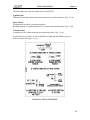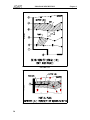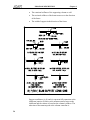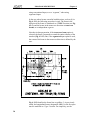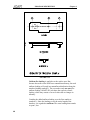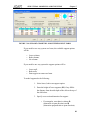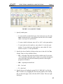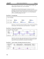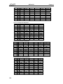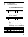
1
STRUCTURAL CONCRETE SOFTWARE ADAPT RC 2010 For Design of Reinforced Concrete Floor Systems and Beam Frames USER MANUAL Vol1_0410_0-3 Copyright 2010 [email protected] www.adaptsoft.com ADAPT Corporation, Redwood City, California, 94061, USA, Tel: +1 (650) 306-2400 Fax +1 (650) 306-2401 ADAPT International Pvt. Ltd, Kolkata, India Tel: +91-33-302 86580 Fax: +91-33-224 67281 LIST OF CONTENTS Content LIST OF CONTENTS OVERVIEW......................................................................................................1 GETTING STARTED ......................................................................................7 SIGN CONVENTION ....................................................................................11 PROGRAM DESCRIPTION.........................................................................15 4.1 GENERAL.............................................................................................................17 4.2 GEOMETRY .........................................................................................................17 4.2.1 Cross-Sectional Geometry .........................................................................17 4.2.2 Other Geometrical Features .......................................................................22 4.2.2.1 Effective Width ...........................................................................22 4.2.2.2 Span Length ................................................................................22 4.2.2.3 End-support Conditions...............................................................22 4.2.2.4 Interior Support Conditions.........................................................23 4.2.3 Customary Changes in Geometry of Beam/Slab .......................................25 4.2.3.1 Drop Caps and Drop Panels for Slabs .........................................26 4.2.3.2 Haunched Beams.........................................................................28 4.2.3.3 Beams Normal (Transverse) to Direction of Frame ....................29 4.2.4 Column Geometry and End Conditions .....................................................31 4.2.5 Width of Support for Moment Reduction ..................................................32 4.2.6 Structural Modeling of Slabs .....................................................................32 4.2.6.1 General ........................................................................................32 4.2.6.2 Tributary or Unit Strip Modeling ................................................33 4.3 LOADING .............................................................................................................36 4.3.1 Number of Loads .......................................................................................36 4.3.2 Classes and Types of Loading ...................................................................36 4.3.2.1 Classes of Loading ......................................................................36 4.3.2.2 Types of Loading ........................................................................37 4.4 4.3.3 Skipping of Loads (Pattern Loading).........................................................43 4.3.4 Load Combinations....................................................................................44 DESIGN CAPABILITIES .....................................................................................44 4.4.1 Definition of Terms ...................................................................................44 4.4.2 Analysis and Design Steps.........................................................................45 4.4.2.1 Serviceability...............................................................................45 4.4.2.2 Strength .......................................................................................45 4.5 INVESTIGATION CAPABILITIES .....................................................................46 WORKSPACE ................................................................................................47 i LIST OF CONTENTS Content 5. OVERVIEW .......................................................................................................... 49 5.1 THE MAIN PROGRAM WINDOW ..................................................................... 49 5.1.1 Main Program Window Menu Items and Corresponding Tools ................ 50 5.1.1.1 File Menu .................................................................................... 50 5.1.1.2 Action Menu ............................................................................... 51 5.1.1.3 View Menu.................................................................................. 51 5.1.1.4 Options Menu.............................................................................. 52 5.1.1.5 Window Menu............................................................................. 53 5.1.1.6 Help Menu .................................................................................. 53 5.2 ADAPT-RC INPUT SCREEN............................................................................... 53 5.2.1 ADAPT RC-Input Menu Items and Tools ................................................. 56 5.2.1.1 File .............................................................................................. 56 5.2.1.2 Project ......................................................................................... 56 5.2.1.3 Geometry..................................................................................... 56 5.2.1.4 Loads........................................................................................... 57 5.2.1.5 Material ....................................................................................... 57 5.2.1.6 Criteria ........................................................................................ 57 5.2.1.7 Execute........................................................................................ 57 5.2.1.8 Tools ........................................................................................... 57 5.2.1.9 Window....................................................................................... 58 5.2.1.10 Structure View ............................................................................ 58 5.2.1.11 View Tools Toolbar .................................................................... 58 BASIC PROGRAM OPERATIONS ............................................................ 61 6. OVERVIEW .......................................................................................................... 63 6.1 START A NEW PROJECT ................................................................................... 63 6.2 OPEN AN EXISTING PROJECT ......................................................................... 63 6.3 SAVE INPUT DATA ............................................................................................ 63 6.4 SAVE INPUT DATA AS DEFAULT ................................................................... 64 6.5 SELECT SYSTEM OF UNITS ............................................................................. 64 6.6 CONVERT SYSTEM OF UNITS ......................................................................... 65 6.7 SELECT DESIGN CODE ..................................................................................... 65 STRUCTURAL MODELING AND EXECUTION.................................... 67 7 OVERVIEW .......................................................................................................... 69 7.1 PROJECT INFORMATION.................................................................................. 69 7.2 7.1.1 Specify General Project Information ......................................................... 69 7.1.2 Specify Analysis and Design Options........................................................ 71 GEOMETRY ......................................................................................................... 72 7.2.1 Specify Span Geometry ............................................................................. 73 7.2.1.1 Prismatic (Uniform) Spans.......................................................... 73 7.2.1.2 Non-prismatic (non-uniform) spans ............................................ 75 ii LIST OF CONTENTS 7.3 7.4 7.5 Content 7.2.2 Specify Effective Flange Width.................................................................78 7.2.3 Specify Geometry of Drop Cap and/or Transverse Beam..........................79 7.2.4 Specify Geometry of a Drop Panel ............................................................80 7.2.5 Specify Support Geometry and Stiffness ...................................................80 7.2.6 Specify Support Boundary Conditions ......................................................82 LOADS ..................................................................................................................84 7.3.1 Specify Dead, Live and Other loads ..........................................................84 7.3.2 Specify Lateral Loads ................................................................................86 MATERIAL...........................................................................................................87 7.4.1 Specify Concrete Material .........................................................................87 7.4.2 Specify Reinforcement Material ................................................................88 CRITERIA .............................................................................................................89 7.5.1 Specify Base Non-Prestressed Reinforcement...........................................89 7.5.2 Specify Minimum Covers ..........................................................................90 7.5.3 Specify Minimum Bar Extension...............................................................90 7.5.4 Specify Load Combinations.......................................................................91 7.5.5 Specify the Design Code............................................................................92 7.6 EXECUTION.........................................................................................................93 7.7 INVESTIGATION DATA AND EXECUTION ...................................................93 VIEW/VALIDATE RESULTS ......................................................................95 8 OVERVIEW ..........................................................................................................97 8.1 ADAPT-RC SUM SCREEN..................................................................................97 8.1.1 ADAPT-RC Sum Menu Items and Corresponding Tools..........................98 8.1.1.1 File menu.....................................................................................98 8.1.1.2 Graphs menu ...............................................................................99 8.1.1.3 Options menu ............................................................................101 8.1.1.4 Window menu ...........................................................................101 8.1.1.5 Help menu .................................................................................101 8.1.1.6 Summary Report .......................................................................101 REPORTS......................................................................................................109 9 OVERVIEW ........................................................................................................111 9.1 REPORT GENERATOR SCREEN .....................................................................111 9.2 HOW TO CREATE REPORT .............................................................................112 9.3 DESCRIPTION OF REPORT SECTIONS .........................................................113 9.3.1 Report Cover Page ...................................................................................114 9.3.2 Table of Contents.....................................................................................115 9.3.3 Concise Report.........................................................................................118 9.3.4 Compact Report .......................................................................................122 9.3.4.1 Section 1- User Specified General Analysis and Design Parameters.....................................................................123 9.3.4.2 Section 2: Input Geometry ........................................................124 iii LIST OF CONTENTS Content 9.3.4.3 Section 3: Input Applied Loading............................................. 129 9.3.4.4 Section 4: Calculated Section Properties .................................. 130 9.3.4.5 Section 5: Moments, Shears and Reactions .............................. 132 9.3.4.6 Section 6: Moments Reduced to Face of Support ..................... 134 9.3.4.7 Section 8: Factored Moments and Reactions Envelope ............ 135 9.3.4.8 Section 9: Factored Lateral Moments Envelope ....................... 136 9.3.4.9 Section 10: Mild Steel - No Redistribution............................... 137 9.3.4.10 Section 11: Mild Steel –Redistributed ...................................... 140 9.3.4.11 Section 12: Shear Reinforcement.............................................. 140 9.3.4.12 Section 13: Punching Shear Reinforcement.............................. 141 9.3.4.13 Section 14: Deflections ............................................................. 142 9.3.4.14 Section 16: Unbalanced Moment Reinforcement ..................... 143 9.3.5 Detailed Report....................................................................................... 144 9.3.5.1 Section 23: Detailed Moments .................................................. 144 9.3.5.2 Section 24: Detailed Shears ...................................................... 144 9.3.5.3 Section 25: Factored Moments and Reactions .......................... 145 9.3.5.6 Section 26: Factored Lateral Moments ..................................... 145 9.3.5.7 Section 29: Detailed Rebar........................................................ 146 9.3.5.8 Section 30: Punching Shear Reinforcement.............................. 146 9.3.5.9 Section 32: Unbalanced Moment Reinforcement ..................... 147 9.3.5.10 Section 33: Investigation Mode ................................................ 147 9.3.6 Graphical Report...................................................................................... 148 9.3.6.1 Deflection.................................................................................. 148 9.3.6.2 iv Load Cases................................................................................ 148 Chapter 1 OVERVIEW 1 OVERVIEW Chapter 1 ADAPT-RC is a powerful and sophisticated computer program for the analysis and design of one-way or two-way reinforced concrete floor systems and beams. It is based on a single-story frame analysis with upper and lower columns or walls. For two-way floor systems the Equivalent Frame Method (EFM) of ACI can be used as an option. ADAPT-RC is a Windows-based program. The following lists the some of the features of the program. • ADAPT-RC treats multi-span continuous slab/plate and beam frames with or without cantilevers at their ends. • In addition to drop caps, ADAPT-RC allows drop panels of different sizes to be specified for different spans. Having a general one-story frame analysis module for variable sections, ADAPT-RC can accurately model a wide range of drop cap/panel geometries. Locally thickened slabs, also referred to as slab bands, are handled as an integral part of the slab/support structure. • The slab region/beam may be supported by walls, beams, or columns with different connection details such as clamped, rotationally free, and more. • ADAPT-RC fully incorporates the Equivalent Frame Method as described in ACI-318 with no simplifications. • In addition to the capability to handle the conventional configurations of column capitals and drop panels, ADAPT-RC allows the user to define a wide range of cross-sectional shapes. The software allows for the cross-section of the member to change along the length of a span, with abrupt steps, at the top, bottom, or both. • For flanged beams, you can either select the software’s built-in effective width computation, based on ACI-318, or input a userdefined alternative effective width. • Using the geometry of the structural model input and the userspecified material density, the program calculates the selfweight loading of the structure for combination with other loads. The calculated values of the selfweight are reported in the program’s output. • Uniform, line, partial, triangle, variable, trapezoidal, concentrated loads and moments may be specified in practically unlimited numbers and variations. 3 OVERVIEW 4 Chapter 1 • All three systems of units, the American customary units (ft-lb.), SI units (mm, Newton), and the MKS unit (m, kg), can be executed from the same copy of the software. Also, all the different codes are integrated into a single version. Data generated in one system of units can be converted into another system by the program. • You can either edit the factory-set, or define your own default values for input of data, while retaining the option to revert to factory-set default values if you so choose. • Input to ADAPT-RC is by means of a user-friendly, free-format, context-sensitive, full-screen input editor. The user may freely browse through, view, and modify the input prior to execution or saving of data. • ADAPT-RC performs a thorough strength analysis and design and determines any mild reinforcement that may be necessary to meet the ultimate strength limit conditions both in bending and shear. • Other code requirements, such as the minimum reinforcement requirements, are also checked and a listing of the reinforcement based on different criteria is reported. • Bar sizes and lengths are selected and reported both in a graphical and tabulator format, ready to be entered on the structural drawings. • The punching shear option checks the adequacy of the column caps as well as the immediate slab/drop panel region beyond the cap and, if required provides the punching shear reinforcements based on the selected code provisions. For one-way slabs and beams, a one-way shear analysis is carried out. Shear reinforcement is calculated and the stirrup requirements are given. • ADAPT-RC has an “Investigation Mode” that allows the users to forecast the effects of moment demand, as well as provided steel for the given geometry, material and loading of the design. There are three analysis options available. The first option permits the user to input the provided steel at 1/20th points of the span as well as the faces of support. Based on the input data, ADAPT-RC calculates the moment capacity. The second option applies the design loading along with the user defined provided steel to calculate the demand versus the capacity. The final option allows the user to input the demand moment as well as the provided steel. ADAPT-RC then calculates the moment capacities. OVERVIEW Prerequisite system data: Geometry, Material, Loading Loading Input Demand Moment (Mu) As, Av Provided Demand Moment (Mu) Output Moment Capacity (fMn) Chapter 1 Design 1 X Analysis Options 2 X X X X X X X 3 X X X FIGURE 1-1 CHART OF DESIGN AND REVIEW • The geometry of the structural model can be viewed on the screen in a three-dimensional space along with the input screen. The capability to rotate, pan, zoom and view the model allows the user to examine the structure in detail prior to the execution of the program. Errors in data entry or modeling are readily detected when user’s input is displayed on the computer screen. Hard copies of the graphical display of the structural model can be readily obtained. • ADAPT-RC uses the detailed analysis scheme throughout its operation. This scheme is based on 1/20th point values along each span, in addition to the face-of-support and other sections with change in geometry. However, to retain the simplicity of presentation of the report, in addition to the optional 1/20th point reports, a summary of the solution is compiled for the left, center and right of each span. • In addition to graphical reports, the outcome of the analysis and design is composed into a clear text file that can be viewed, edited and printed by you. The content and extent of the report can be controlled by you through a user-friendly menu. The result may be compiled in several formats, such as concise, compact and detailed, thus saving lengthy printouts if only the critical data are sought. • It is also possible to generate a one-page graphical summary report that extracts and incorporates all important design information in an easy-to-interpret format. The report may also be exported as a DXF file for incorporation into construction documents. • The graphical display option of ADAPT-RC provides a vivid exposition of the distribution of calculated values along the entire structure or for its selected members. The display includes moments, shears, deflections, and reinforcement required/provided. Each graph may be printed or exported as a .bmp or a metafile. • ADAPT-RC input data is stored in a single file with the .ADB extension. However, the program is also backward compatible with input generated by earlier Windows versions of the program. 5 OVERVIEW • 6 Chapter 1 ADAPT-RC is integrated into the ADAPT-Builder software suite. Structural models generated using the Modeler module of the Builder suite can automatically be transferred to ADAPT-RC for analysis and design. This capability provides a seamless link between the Finite Element Method of ADAPT-Builder and ADAPT-RC. Chapter 2 GETTING STARTED 7 GETTING STARTED Chapter 2 Installation: 1. Install the hardware Key (dongle) by inserting it into a USB or parallel port. If a printer is connected to the parallel port, the Key can be sandwiched between the printer cable and the computer parallel port. The insertion of the Key does not impact the normal operation of your computer. 2. Invoke the executable file on the program CD. An installation program will open and provide further instructions. Follow the screen instructions until setup is complete. Execution: 1. Open the ADAPT-RC program by double-clicking on the icon on your desktop or navigating through your START menu. 2. To test the computer environment for compatibility with ADAPT software, select Open from the File menu and select the example MNL5-2.ADB in the Examples subdirectory. This test example is in US customary units. Use this example to verify that the program runs. Execute the program. After the execution stops, you can view the results 9 Chapter 3 SIGN CONVENTION 11 SIGN CONVENTION Chapter 3 The following is the sign convention used in ADAPT-RC. Applied loads Downward loads and counterclockwise moments are considered positive (Fig. 3.1 (a)). Span Actions Counterclockwise shear is considered positive. Bending moment is considered positive if it causes tension at the bottom. Fig. 3.1 (b) Column actions Counterclockwise column moments are considered positive Fig. 3.1 (d). Positive direction of frame as well as definition of right and left tributary region is defined as shown in Figure 3.1 (c). FIGURE 3-1 SIGN CONVENTION 13 Chapter 4 PROGRAM DESCRIPTION 15 PROGRAM DESCRIPTION 4.1 Chapter 4 GENERAL The following is an overview of the scope and capability of ADAPT-RC. For detailed information on its operation, including input generation, and execution refer to Chapter 6 of this manual. For the theoretical background to the calculations performed by the program refer to Theory Chapter in Volume 11. 4.2 GEOMETRY 4.2.1 Cross-Sectional Geometry ADAPT-RC handles beams, one-way slabs and two-way floor systems. The two-way floor system can be solid slab, waffle or joist construction. Spans may be prismatic or nonprismatic. The treatment of slabs in ADAPT-RC is based on a single story slab and/or beam frame modeling with columns/walls extending below and above the slab/beam. The frame consists of one line of column supports along with the associated tributary of the slab. A simple example of floor modeling is shown in Fig. 4.2-1. A floor system (Fig. 4.2-2) consists of the essentially horizontal diaphragm, which spans the vertical supports and is intended to provide a surface for support of gravity loading. Beams, changes in the slab thickness, offsets (steps) above and below the slab, and openings are common, essential features of a floor system. For purpose of design, regions of the slab are commonly designated by specific names. A support line is a hypothetical line defined by the designer that joins adjacent supports (Fig. 4.2-3). A bay is the slab area bounded by two adjacent support lines. A panel is a portion of a slab enclosed by four adjacent columns. A design strip consists of a line-of-support together with a portion of the slab on each side of the line-of-support, called the tributary (Fig. 4.2-4). Through extensive modeling features integrated into ADAPT-RC, complex beam and slab geometries with nonstandard support conditions can be readily modeled. The ACI recommended equivalent frame modeling is built into ADAPT-RC as an option of slab frame analysis. The geometry of the structural model includes the cross-sectional definition of the slab/beam for each span, span length, and the details of the slab/beam supports. 17 PROGRAM DESCRIPTION Chapter 4 FIGURE 4.2-1 Each span may be composed of a uniform cross-section, in which case the span is referred to as prismatic, or it may be composed of a number of segments, each having a different cross-sectional geometry, in which case that span is referred to as nonprismatic. A segment is a portion of span with uniform cross section and in the direction of the frame being analyzed. Each segment of the span can be assigned a cross-sectional geometry from the library of ADAPT-RC. The list of geometries currently in the ADAPTRC library is shown in Fig. 4.2-5. 18 PROGRAM DESCRIPTION Chapter 4 FIGURE 4.2-2 In order to facilitate input of common geometries, two input modes are included in ADAPT-RC. One is for input of common geometries, such as slabs with or without drop caps and drop panels. The other is for input of highly irregular slab or beam geometries. For the common geometries, the input is intuitive. That is to say, the user inputs span length, cap and drop dimensions and particulars of features that occur in common geometries. This mode of input is referred to as the customary input. Furthermore, the customary mode of input allows the user to enter a representative strip of slab, referred to as unit strip. This feature is described in more detail in another section of this chapter, Structural Modeling of Slabs. 19 PROGRAM DESCRIPTION FIGURE 4.2-3 FIGURE 4.2-4 20 Chapter 4 PROGRAM DESCRIPTION Chapter 4 FIGURE 4.2-5 For the unusual case, the user subdivides the span into segments, each having a uniform cross-section. The geometry of each segment is then entered independently. This mode of input is referred to as segmented input. Segmented input allows the user to specify steps, openings, transverse beams and other nonuniform conditions. In two-way slab construction, where the drop panels of one support extend and merge with the drop panels of the next support in the same span, a cross-sectional condition referred to as Type 2 in Fig. 4.2-5 is used. This geometry is referred to as slab band, or wide shallow beam. A slab band is treated differently from a regular beam. In the former the total width of the slab (tributary) is considered effective in resisting the loads. This is in 21 PROGRAM DESCRIPTION Chapter 4 accordance with the equivalent frame concept. However, for a beam, the effective width in many cases is less than the beam's tributary, as described in the next section. The information on the geometry of drop caps, drop panels, or beam haunches is defined and input independently from slab/beam geometry. The slab/beam geometry covers only the typical region of a span, commonly its central region. 4.2.2 Other Geometrical Features 4.2.2.1 Effective Width In flanged beam design, often it becomes necessary to assign a smaller width than the flange tributary (effective width) to act with the beam stem in resisting the flexure of the beam. In ADAPT-RC, according to the user's choice, the effective width of a flange is either calculated using ACI recommendations, or it is input by the user. For inverted L- or T-sections, the effective width is applied to the bottom flange. For an I-section with a wide flange, the effective width is calculated for both the top and the bottom flanges. The smaller of the two is selected and applied to the entire section. 4.2.2.2 Span Length Span length is measured from and to support centerlines. Support centerlines are also referred to as system lines or frame lines. 4.2.2.3 End-support Conditions The end-support is defined as the last support of the slab/beam at its left or right end. Each slab/beam, therefore, has two end supports. Fig. 4.2-6 shows the end support at left, together with a partial elevation of the end-span. Three conditions for endsupports, as described below, are implemented in ADAPT-RC: Cantilever Support: Occurs when part of the span extends beyond the end support. Again, the end support may or may not be a moment connection with its wall/column support. 22 PROGRAM DESCRIPTION Chapter 4 FIGURE 4.2-6 Regular Support: Occurs when the slab/beam terminates over a wall, column or beam. The question of whether the support can develop a bending moment or not is treated elsewhere in the description of support/slab connections. At a regular support the slab/beam is free to rotate. The magnitude of rotation, however, is controlled by the stiffness of the column/wall support. In the terminology of ADAPT-RC and for data input, this condition is termed rotationally not fixed to distinguish it from the condition of full fixity (zero angle of rotation), which is called rotationally fixed. Since the two end supports are treated independently, data for each is input separately. 4.2.2.4 Interior Support Conditions The different interior support conditions that can be modeled by ADAPT-RC are shown in Fig. 4.2-7. Observe that for all the conditions shown, the deflection at the centerline of support (system line) is considered to be zero. The shortening of columns or the sinking of supports is not included in the formulation. The differences between the formulations of the support options illustrated in the diagram lie in: 23 PROGRAM DESCRIPTION Chapter 4 • The rotational stiffness of the supporting column or wall. • The torsional stiffness of the beam transverse to the direction of the frame. • The width of support in the direction of the frame. FIGURE 4.2-7 Support conditions (a), (b) and (c) represent full connection at the slab/beam junction. In these cases moment transfer between the slab/beam and the column is based on the column's stiffness. The reduction of the moment peak at the column centerline is 24 PROGRAM DESCRIPTION Chapter 4 governed, among other factors, by the width of column in the direction of the frame. The wall support condition (d) provides a finite support width that result in flattening of the moment peak at the support centerline. Whether or not a moment will also be transferred to the support is decided by the user, and affected through the input data from the construction details of the joint. For the beam support condition (e) of the diagram, only the torsional stiffness associated with the beam cross-section and its length affect the solution for two-way systems. This type of support is referred to as transverse beam support and is within the scope of ADAPT-RC. In one-way slabs, the transverse beam acts as a thickening of the slab at its supports. A one-way slab, by definition, deflects in strips of identical shape. As a result, the beam will not be subject to torsion. The increased thickness due to the beam, however, affects the distribution of moment in the slab. The slab may be designed for the moment at the face of the transverse beam. ADAPT-RC, at the user’s option, accounts for the added stiffness of the transverse beam and can reduce the design moment to the face of the beam for the design of the slab. Support type (f) is basically the same as the wall support shown in (d), but is constructed to minimize generation of forces in the direction of the frame due to shortening of the slab/beam. A knife edge support as shown in (g) is one for which no moment is transferred between the support and the slab/beam. In this case the system line moments calculated from the analysis are not reduced for design. 4.2.3 Customary Changes in Geometry of Beam/Slab ADAPT-RC can handle both prismatic and nonprismatic slabs. A nonprismatic member is defined as one in which the cross-section of the member (slab or beam) changes between two adjacent supports. A haunched beam and a slab with drop caps or panels are examples of nonprismatic members. All details of changes in the cross-sectional geometry of a member are 25 PROGRAM DESCRIPTION Chapter 4 rigorously accounted for in the formulation of ADAPT-RC. There are no ADAPT-RC approximations to the structural model. This section describes the scope of the geometries covered by ADAPT-RC and modeling guidelines for common changes in geometry. 4.2.3.1 Drop Caps and Drop Panels for Slabs Fig. 4.2-8 shows the elements of the geometry at an interior support provided with a Drop Cap and Drop Panel. Drop caps and drop panels are also referred to as step 1 and step 2 of the geometry change. FIGURE 4.2-8 26 PROGRAM DESCRIPTION Chapter 4 When drop caps and/or drop panels are present, the span is treated as a nonprismatic member. The added stiffness due to caps and panels is included in the analysis. Several examples of column/slab junction geometries are given in Fig. 4.2-9. FIGURE 4.2-9 Any support can have a drop cap and/or a drop panel independent of the remaining supports. The caps and panels at different supports need not have the same geometry. It becomes necessary, 27 PROGRAM DESCRIPTION Chapter 4 therefore, to define fully the drop cap and panel geometry at all supports. To facilitate the input routine, in particular when repeated geometries are used, the program is provided with a number of default options. It is not necessary to have stepped geometries on both sides of a support. For each support, the total depth at step 1 (parameter CAPT in Fig. 4.2-8) must be larger than or equal to the thickness at step 2 (DROPTL, DROPTR). Either the length or width of step 2, or both, shall be larger than the corresponding values of step 1. In other words, it is assumed that as midspan is approached from the support, the depth of each succeeding step reduces, whereas its width and length (the horizontal dimensions) may or may not increase. If this assumption does not apply to the problem at hand, the general nonprismatic (segmented) input option must be used. 4.2.3.2 Haunched Beams Haunched beams are modeled using segments to represent distinct steps. Each span can have a maximum of seven segments; normally three steps are used for each haunch. The user determines the step sizes and locations. Fig. 4.2-10 (a) illustrates an example of a haunched beam with sloping faces. Fig. 4.2-10(b) demonstrates how to model it. 28 PROGRAM DESCRIPTION Chapter 4 FIGURE 4.2-10 4.2.3.3 Beams Normal (Transverse) to Direction of Frame Fig. 4.2-11 shows beams normal to the direction of the modeled frame either (a) without, or (b) in conjunction with beams in direction of the frame. FIGURE 4.2-11 In case (a), where the existing beams are all in the transverse direction, the beams may be modeled as “transverse beams,” when 29 PROGRAM DESCRIPTION Chapter 4 using conventional input, or as a “segment,” when using segmented input. In the case where beams extend in both directions, such as (b) in Fig. 4.2-11, the following procedure is used. The beam in the direction of the frame is considered as a TYPE 2 section (see Fig. 4.2-5), and the beams in the transverse direction as transverse beams, or an independent segment Note that in data preparation, if the transverse beam option is selected, the beam is assumed to extend the entire tributary of the member (Fig. 4.2-12). But, if the segmented input option is used, the extent of the beam in the transverse direction is defined by the user. FIGURE 4.2-12 Fig. 4.2-12 identifies the frame line on gridline 5. As previously stated, the longitudinal beam (designated ABDC) in the first span must be modeled as a Type 2 section. For simplicity, use the 30 PROGRAM DESCRIPTION Chapter 4 customary input generation library provided in the ADAPT-RC. The transverse beam is then entered with the following particulars: Width to the left Width to the right Depth Cap depth 4.2.4 = = = = GO OH Depth of beam Depth of beam (including slab) Column Geometry and End Conditions The connection of a column at its ends is described with the Column Boundary Conditions and is referenced in the ADAPT-RC output as CBC. ADAPT-RC treats four column boundary conditions as illustrated in Fig. 4.2-13. The conditions shown in the figure are equally applicable to wall supports, or a simple support as indicated at gridline A in the figure. These conditions are: CODE CONDITION 1 2 3 4 Standard; fixed at both ends Hinged at near end, fixed or hinged at far end Fixed at near end, hinged at far end Fixed at near end, roller with rotational fixity at far end FIGURE 4.2-13 In describing the geometry of a column or wall support, the following terminology is used: 31 PROGRAM DESCRIPTION • Chapter 4 Column/wall depth (D): Dimension of support parallel to direction of frame. • Column/wall width (B): Dimension of support perpendicular to direction of frame. • Simple support: A simple support as shown at gridline A may be modeled using boundary condition 2, with a non-zero column height. A finite depth (D) can be specified to take advantage of the actual support width in reducing the system line bending moment to the face of support. It is recommended that the actual support width (B) be specified if the punching shear calculation option is invoked. By doing so, the reduction of moment to the face of support and punching shear calculations can take place without transferring a moment to the support. For the purposes of analysis and design, circular columns are transformed by ADAPT-RC into square columns having the same cross-sectional area. 4.2.5 Width of Support for Moment Reduction The analysis of ADAPT-RC is based on centerline moments (moments at the center of the joints). Moments can be reduced to the face of the supporting column or beam by selecting the Reduce moment to face-ofsupport option during data input. For column-supported slabs and beams, the support width is typically D, the dimensions of the column in the direction of the frame. In one-way slab systems, the width of the beam is typically used as the support width for the slab model. Note that the support width is used only to determine moment reduction; it has no effect on support fixity. Figure 4.2-14 shows the support width of several common conditions. 4.2.6 Structural Modeling of Slabs 4.2.6.1 General This section describes options in modeling slab geometry. The geometry consists of a slab's cross-sectional shape at its midspan, total width (tributary), depth and other parameters as given earlier in this chapter. Two schemes may be used for ADAPT-RC in modeling a slab. 32 PROGRAM DESCRIPTION Chapter 4 FIGURE 4.2-14 The first scheme is called Tributary input, the second Unit strip input. Both schemes yield the same results. The selection is based on the preference of the user and the specific requirements of the structure. Once a scheme is selected, the input should be consistent with that selection throughout the data. 4.2.6.2 Tributary or Unit Strip Modeling The tributary is composed of a region to the left and a region to the right of the frame line (Fig. 4.12-15). The sum of the left and right tributaries is called total tributary. The total tributary can vary within each span and from span to span. Left Tributary: The portion of the tributary width that falls to the left of the frame line of a structural model. Fig. 4.2-16 defines the terms left and frame or system line in the context of the ADAPTRC program. See also Fig. 4.2-16 for an example of ADAPT-RC’s point of reference in defining “Left” and “Right”. 33 PROGRAM DESCRIPTION Chapter 4 FIGURE 4.2-15 Right Tributary: This portion is analogous to the left tributary. Unit Strip: A unit strip is an imaginary strip parallel to the span with a width equal to or less than the total tributary. The concept of unit strip is introduced to assist the user in data input and evaluation of output results. Although the unit strip width is typically 12 in. or 1000 mm, any reasonable value may be used. The unit width has no affect on the analysis as long as the total tributary width is modeled correctly. Users will get the same results with both methods. Unit strip modeling (Fig 4.2-15). In unit strip modeling, the tributary is modeled by specifying a unit strip width as the ‘b’ dimension along with the width multiplier, left and right multipliers. The width multipliers (<−Μ and Μ−>) indicate the number of times the unit strip needs to be multiplied to cover the left and right tributaries. The multipliers need not be whole numbers. If the total tributary is modeled as one strip, the sum of left and right multipliers must add up to one. 34 PROGRAM DESCRIPTION Chapter 4 Tributary Modeling: In tributary modeling, the total tributary width is entered as the “b” dimension. The width multipliers (<-M and M->) are used to indicate how much of the tributary falls on either side of the frame line. The sum of the left and right multipliers should be one.. Example: Model the following tributary using A) unit strip method B) tributary method. Total tributary = 300 in. Left tributary = 180 in. Right tributary = 120 in. A) Unit strip method: b = 12 in. <-M = 15 M-> = 10 Total width = Left tributary + Right tributary = 12*15 +12*10 = 180 + 120 = 300 in. B) Tributary method: b = 300 in. <-M = 0.60 M-> = 0.40 Total width = Left tributary + Right tributary = 300*0.60 +300*0.40 = 180 + 120 = 300 in FIGURE 4.2-16 35 PROGRAM DESCRIPTION Chapter 4 In the case of slabs with drop caps, or slabs with drop caps and drop panels, the actual strips are not all identical in cross-sectional geometry. The program recognizes and allows for changes in geometry across the width of the span. Corrections necessary over the drop cap and drop panel regions are automatically implemented by the program from the drop cap and drop panel data. 4.3 LOADING The loading applied to the structure, such as selfweight, superimposed dead loading, live loading and investigation loading, are discussed in this section. 4.3.1 Number of Loads Each span may be specified to have several load entries. The number of different loads on any span, as well as the number of total loads which may be specified for the entire frame, are unlimited for practical purposes. 4.3.2 Classes and Types of Loading 4.3.2.1 Classes of Loading Five classes of loading are treated, namely: (i) Selfweight (SW), (ii) Superimposed Dead Load (SDL), (iii) Live Load (LL), (iv) Other user defined Load case, and (v) Lateral Loading. Selfweight: The program has the option of calculating the selfweight of the structure automatically from its geometry and unit weight. The selfweight computation of ADAPT-RC is precise. The weight of each segment of span is computed based on the volume of the respective segment. If you haven’t selected the option to calculate automatically, you can enter selfweight as independent. Superimposed Dead Loading can be entered as independent from selfweight. In this case the user has an option to define different load factors for superimposed and selfweight. Live Loading is entered as independent from the dead load entries. These loadings need not be specified for obtaining a solution. 36 PROGRAM DESCRIPTION Chapter 4 Other Loading may be any loading that user applies on the structure. Internally the program doesn’t calculate creep effects for this loading and doesn’t skip it. Lateral Loading is entered as concentrated moment acting at each face of support. The detail explanation about the treatment of lateral loads is given in Chapter 5 of the manual. 4.3.2.2 Types of Loading Eight types of loading are covered by ADAPT-RC, namely: • Uniformly distributed loading over the entire surface of a span (L-U). • Concentrated loading at a given distance along a span (L-C). • Partial uniform loading covering specific portions of a span surface (L-P). • Applied moment at a given distance along a span (L-M). • Line loading along a portion or the entire length of a span (LL). • Triangle loading along a portion or the entire length of a span (T-R). • Variable loading along a portion or the entire length of a span (T-V). • Trapezoidal loading along a portion or the entire length of a span (T-Z). Other loading distributions should be modeled as a combination of the preceding eight types. The loading types are shown in Fig. 4.31 acting in their respective positive directions. The positive direction of line loading is the same as partial uniform loading. For further illustration, consider Fig. 4.3-2, which shows the plan and elevation of an irregular, two-span frame. In addition to selfweight, the frame is subject to a uniform live loading. In ADAPT-RC a uniform loading is assumed to be distributed uniformly over the entire uppermost surface of the member with a constant intensity per unit area. However, in the case of inverted Tsections or I-sections, ADAPT-RC distributes the uniform loading over the larger of the two surface areas. The two-span structure includes other loads as shown in part (a) Fig. 4.3-3. 37 PROGRAM DESCRIPTION Chapter 4 FIGURE 4.3-1 CONTINUED.. ADAPT-RC automatically calculates and generates the frame loadings from minimum user input. The outcome of ADAPT-RC's loading computations is listed in the output for the user’s record or verification. For the benefit of the interested user, by way of an example, the following additional details are presented. 38 PROGRAM DESCRIPTION Chapter 4 FIGURE 4.3-1 Selfweight is calculated from the geometry of the member. Since the tributary as well as thickness of members vary, the selfweight will result in a distribution marked with the encircled 1 in the diagram. Note that where the tributary of a slab changes, the selfweight also changes. 39 PROGRAM DESCRIPTION Chapter 4 FIGURE 4.3-2 Uniform live loading is applied over the surface area. But, because the surface area itself has a nonuniform tributary, the total uniform loading will result in a nonuniform distribution along the member (loading marked 2). The user makes only one entry for uniform loading. ADAPT-RC calculates the respective frame loading, which may consist of several values due to changes in tributary. Consider the added uniform loading over the first cantilever (marked 3). Since the loading covers the entire length of the member, it is regarded as uniform. The same loading that extends to span 1, but 40 PROGRAM DESCRIPTION Chapter 4 FIGURE 4.3-3 covers only a portion to conform with the definition of Fig. 4.3-1 of the length of span 1 (marked 4), is defined as partial loading. Concentrated loading and moments act at specific locations along a span. Note that the position of these actions transverse to the direction of frame does not enter the computation (loadings circled 7 and 8 in Fig. 4.3-3) in the diagram. 41 PROGRAM DESCRIPTION Chapter 4 FIGURE 4.3-4 Line loading refers to superimposed dead, live, or other loading. It is of uniform magnitude in direction of span (loadings circled 5 and 6 in the Fig. 4.3-3). The line loading is not affected by the surface geometry of the member. The difference between partial and line loading is illustrated in Fig. 4.3-4. 42 PROGRAM DESCRIPTION 4.3.3 Chapter 4 Skipping of Loads (Pattern Loading) Skipping of loading, or pattern loading, is limited to live loads, except for the British version of ADAPT-RC in which a proportion of dead loading is also skipped. If load skipping is selected by the user, the program applies the load selectively on various spans in order to obtain the maximum and minimum moments and shears at each 20th point along each span. In the general case, six patterns of loading, as illustrated in Fig. 4.3-5 are necessary to consider, in order to obtain critical values. FIGURE 4.3-5 Note that in skipped loading, for each loaded span, the entire live loading specified for that span is considered active simultaneously. In other words, if a given span has 10 live loads, in the loaded condition of that span all the 10 loads are assumed present. A Skip Factor can be selected by the user if so desired. The skip factor is the factor by which the patterned loading is multiplied. Commonly, a skip 43 PROGRAM DESCRIPTION Chapter 4 factor of 1 or less is assumed. Note that the skip factor is applied only to load patterns 2 through 6 of Fig. 4.3-5. The condition of load on all spans is implemented without a factor. That is to say, the load factor for pattern 1 is considered as 1, regardless of the user's entry. 4.3.4 Load Combinations For the combinations of load cases, the critical values of moments and shears at each 20th point and the reactions are each multiplied by a load factor and combined to obtain the respective maximum and minimum values. Each version of ADAPT-RC has, as a default, the related, codespecified factors. However, the user has the option to override the code factors by entering a different load combination. 4.4 DESIGN CAPABILITIES 4.4.1 Definition of Terms In the context of the present work the following words are used with the emphasis described herein: Analysis is defined as the algorithm and sequence of steps leading to the determination of sectional actions (moments, shears), stresses and deflections, due to each and all of the loads on the structure. The analysis is based strictly on applying the known laws of statics and theorems of solid body mechanics to the structural model selected. Any deviations from the commonly used laws and theorems, such as code simplifications (if employed by ADAPT-RC), are clearly defined in this manual. Design consists of: 44 • Adjustments and Redistribution of moments due to finite dimensions of the structure and post-elastic reserve in Strength; • Load Factors and the Combination of Actions (moments, shears) to obtain the Design Moments, Design Shears, (collectively referred to as design actions, or Factored actions); • Evaluation of the Ultimate Strength of the sections and determination of the required Mild Reinforcing; and • Estimate of deflections beyond the elastic limit. PROGRAM DESCRIPTION 4.4.2 Chapter 4 Analysis and Design Steps Based on current codes, each structure is to be analyzed and designed to meet or exceed the stipulated code requirements for two conditions, namely Serviceability and Strength. 4.4.2.1 Serviceability Serviceability means that the structure should satisfactorily perform its required function during the in- service condition. When applied to a reinforced concrete structure this is translated to mean: • Deflections should be acceptable. • Limiting crack size by providing a minimum amount of mild reinforcement over the supports and at midspans; ensuring durability by limiting cracks and the penetration of moisture and water. ADAPT-RC checks for deflection and minimum reinforcement. 4.4.2.2 Strength Strength check establishes that the structure designed has a minimum code specified margin of safety against collapse. To this end, factored shears and moments (also referred to as design shears and moments) are calculated from the serviceability actions and checked against the strength formulas. If a section is found to be inadequate, mild reinforcement is added to meet the required strength. In some cases the analysis has to be repeated using larger cross-sections. Using the previously described input parameters, ADAPT-RC calculates all moment rebar and shear reinforcing requirements for the slab system. The required rebar is calculated at 1/20th points in each span, as well as each face of support, if desired. Rebar amounts are based upon code specified criteria for all strength and service requirements applicable to the slab system in question. The program will also calculate the total number and length of bars to be placed at each location in the slab, based upon user-specified bar sizes, inflection points and code criteria. Also included in the 45 PROGRAM DESCRIPTION Chapter 4 results is an estimate of the total weight of rebar in the slab and of the average weight per unit area. Shear capacity is checked at critical locations in each span. For two-way slabs the punching shear is checked at each support. For beams and one-way slabs the required shear spacing is calculated at 1/20th points in each span. 4.5 INVESTIGATION CAPABILITIES ADAPT-RC can also be used to analyze an existing beam or slab. The investigation mode allows the user to implement the geometry, loading and material properties already provided in the input-editing mode along with additional variable input. Fig. 1-1 outlines the investigation options implemented in ADAPT-RC. In option 1, the user inputs the slab geometry and available reinforcement, and ADAPT-RC calculates the moment capacity of the slab at 1/20th points for each span. Alternatively, in option 2 the user inputs the slab geometry, available reinforcement, and loading, and ADAPT-RC calculates the moment capacity for comparison to the moment demand at each 1/20th point. In option 3 the user inputs the geometry, available reinforcement and the moment demand on the slab, and ADAPT-RC again calculates capacities for comparison. Deflections and required reinforcement are also calculated for options 2 and 3. In all cases the results may be viewed and printed in graphical and tabulated formats. 46 Chapter 5 WORKSPACE WORKSPACE 5. Chapter 5 OVERVIEW This chapter describes Graphical User Interface (GUI) for the main program screen and data input module of ADAPT-PT program. All program functions, including data entry and program execution are accessed through the Main Program window. The data entry is done through separate program module called ADAPT-PT Input. 5.1 THE MAIN PROGRAM WINDOW Figure 5.1-1 shows the main ADAPT-RC program screen as it appears once a project has been opened. Main Program Title Bar Main Menu Bar Main Toolbar Hint Window Status Bar FIGURE 5.1-1 MAIN PROGRAM WINDOW 49 WORKSPACE Chapter 5 Main Program Title Bar. Contains program name and name and location of the opened file. Main Menu Bar. Lists all available menus in main program window. Menu options will be grayed out when they are not applicable. For example, if there is no project open, the Save As, Close and Print options on the File menu will be grayed out. Main Toolbar. Main Toolbar contains all available tools in the main program window. The tools will not be available when they are not applicable. For example: • If you open ADAPT-RC program available tools are: • If you open existing file the main toolbar contains the following options: Status Bar. Status bar gives you information about project name, selected design code, units, execution mode, key type, current date and time. To turn Status Bar on or off go to View -> Status Bar. Hint Window. Hint window gives you information on how to proceed if you want to edit, execute or view your structure. To close the Hint Window, right click anywhere on the screen. 5.1.1 Main Program Window Menu Items and Corresponding Tools All options that can be accessed by the main program menus are listed below. For the commands that might be activated using the toolbar, the appropriate icon is displayed next to the feature. 5.1.1.1 File Menu The File Menu operations are: New. Starts a new project. Open. Opens an existing project. 50 WORKSPACE Chapter 5 Save As. Saves both the input files and the results report file under a user-specified filename. Save As Default Values. Once you save data using this option, the program will open all the new projects in the future using the values you saved. To change the default values, open a new file, modify the parameters of your choice, and re-save it using Save As Default Values. Close. Closes the currently open project. Delete Intermediate Files. Deletes all intermediate calculation files from the current project directory. Export Graph. Allows the user to export the currently active graph as either a bitmap (.BMP) or a Windows metafile (.WMF). Print. Prints the currently active report or graph window. Page/ Print Setup. Sets the paper size, report margins, paper orientation and printer. Exit. Closes all windows and exits the program. 5.1.1.2 Action Menu The Action menu operations are: Enter/Edit Data. Opens the data input editor. Execute Analysis. Executes the program calculations. Enter Investigation Data. Opens the Investigation Data window for the Investigation Mode. The user may quickly refine a design by controlling the steel provided or the design demand. 5.1.1.3 View Menu The View menu operations are: 51 WORKSPACE Chapter 5 Status Bar. Turns the status bar at the bottom of the main window on and off. Graphs. The Graphs menu item opens a submenu, which allows any or all of the Results Graphs to be viewed. The Show Graphs button on the main toolbar displays all graphs. RC Summary. Allows you to see result graphs for moments, forces, and reinforcement for each load combination and envelope. Also it displays the report summary sheet. 5.1.1.4 Options Menu The Options menu operations are: System of Units. Allows the user to select the default units (American, SI, MKS). Design Code. Allows the user to select the default code. ACI Minimum Bar Required. Allows the user to consider or disregard the ACI minimum bar required.?? Investigation Mode. Opens the dialogue box shown below where three different investigation options may be set. (Fig. 5.2-3) FIGURE 5.1-2 Verify Investigation Data. Automatically verifies input data in Investigation Data input box.?? Remember Printer Selection. If this option is checked, the program uses the latest printer settings for all future runs, regardless of the default printer selected in the Windows settings. 52 WORKSPACE Chapter 5 Report Setup. Opens a Report Generator window where the report contents may be set. Graph Properties. Opens a submenu containing a series of graphing features that may be applied to all graphs generated by the program. Spreadsheet Options. Configures the action of the Enter key in all spreadsheet-type windows in ADAPT-RC. The key may be set to control cursor movement. 5.1.1.5 Window Menu The Window menu operations are: This menu controls the arrangement of open windows on the screen. This menu lists which of the graph windows are open. The graphs may be stacked vertically for scrolling, or the windows may be cascaded. 5.1.1.6 Help Menu The Help menu operations are: About ADAPT. Company address and e-mail information. About ADAPT-RC. Program information such as version. Support Programs. Information on how to obtain program support with contact details. Disclaimer. Defines responsibility of the software user. Calculator. Invokes the standard windows calculation. 5.2 ADAPT-RC INPUT SCREEN Project input data is created/edited through separate program module called ADAPT-RC Input. The input editor is used both to enter new projects and edit existing files. 53 WORKSPACE Chapter 5 • To enter a new project either click New on the File menu or click the New button, , on the Main Toolbar. • To edit existing file either click on Enter/Edit Data on the Actions menu on the Main Menu bar, or click the Edit Data button, , on the Main Toolbar. Figure 5.2-1 shows the ADAPT-RC Input screen as it appears once the input editor is opened. RC Input title bar RC Input menu bar RC Input Toolbar 3D Structure View Window Input Form FIGURE 5.2-1 ADAPT-RC INPUT SCREEN RC Input Title Bar. Contains program name, and name and location of the opened file. RC Input Menu Bar. Menu bar lists all available menus in ADAPT-RC Input. RC Input Toolbar. This toolbar contains all available tools in the ADAPT-RC Input. 54 WORKSPACE Chapter 5 Input Form. Each input form is the dialog box that will prompt you to select options or enter required information. When first entering data for a project, you would typically go through the screens in order by clicking on the Next and Back buttons or pressing ALT-N and ALT-B. In subsequent editing, specific screens may be selected from the PT Input menu. If the input form contains a table (Fig. 5.2-2) the right mouse click will give you the following options: • Insert new line • Delete line • Copy selected lines • Paste lines FIGURE 5.2-2 SPAN GEOMETRY INPUT SCREEN Each table contains a Typical row for fast input of data. The typical input row (top row) can be used if several rows in a column have same data. To enter typical values, type the value into the appropriate cell in the top row and then press ENTER. The typical value will be copied to all rows in the column. The value of any field initialized in this manner can be subsequently changed as necessary. Data can be entered in the typical row at random; it is not necessary to enter values in all fields of the typical row. 3D Structure View. Structure View window (Fig.5.2-3) allows you to view the structure, loads, tendons, and rebar in 3D as you enter the data. The Program displays the properties of each component at the bottom of the structure view screen if you bring the mouse pointer over it. Also you can display using right click. You can change the display in 3D window with View Tools toolbar. The toolbar function is explained in Section 5.2.1.11. 55 WORKSPACE Chapter 5 FIGURE 5.2-3 STRUCTURE VIEW WINDOW 5.2.1 ADAPT RC-Input Menu Items and Tools All options that can be accessed by the RC Input menus are listed below. 5.2.1.1 File This menu items have the same function as File menu in the main program screen. (Section 5.1.1.1) 5.2.1.2 Project This menu enables you to specify the project title, structural system and select analysis and design options through General Settings and Design settings input forms. 5.2.1.3 Geometry This menu enables you to access input forms that you use to define geometry of a model. The input forms included in this menu are: 56 • Span geometry • Effective Flange width • Drop cap/transverse beam • Drop panel WORKSPACE • Support geometry • Boundary conditions Chapter 5 5.2.1.4 Loads This menu opens the Loads input form where you can specify the loads. 5.2.1.5 Material This menu enables you to access input forms where you can specify material properties for: • Concrete • Reinforcement 5.2.1.6 Criteria Criteria menu contains all input screens that you use to specify project criteria. The Criteria menu input forms are: 5.2.1.7 • Base Non-Prestressed reinforcement • Minimum covers • Minimum bar extensions • Load combinations • Design code Execute If you click on the Execute menu the program will initiate an analysis. The corresponding tool is Execute Design, , in the Common toolbar. 5.2.1.8 Tools The Tools menu allows you to convert units and change color settings. The menu items are: • Convert units • Color selection 57 WORKSPACE Chapter 5 5.2.1.9 Window This menu controls the arrangement of open graph windows on the screen. The graphs may be stacked vertically for scrolling, or the windows may be cascaded. 5.2.1.10 Structure View If you click on this menu it will open the 3D structure view. 5.2.1.11 View Tools Toolbar This toolbar contains tools for selecting the entities that you want to be visible on the screen, as well as for creating rendered or shaded views of structural models. It is used to zoom in or out, pan, increase scale, create a screen shot, and print. Plan View. It will show structure in plan view. Elevation View. It will show structure in elevation view. Isometric View. It will show structure in 3D isometric view. Free Rotate Perspective View. Wire Frame. Transparent Shader. Solid Shader. Outline Shader. Show/Hide Gridlines. Displays or hides gridlines and reference line. 58 WORKSPACE Chapter 5 Show/Hide Spans. Displays or hides spans of the structural model. Show/Hide Supports. Displays or hides columns and walls of the structural model. Show/Hide Drops/Beam. Displays or hides drop caps and beams of the structural model. Show/Hide Loads. Displays or hides all loads that have been identified as “visible” in the Select/Set View Items window. Show/Hide Rebar. Displays or hides the entire user defined (base) reinforcement. Show/Hide Fixity. Displays or hides all fixity symbols of the supports. Increase Scale Factor. This tool provides you with the option of distorting the dimension of the model in one or more direction, in order to obtain a better view of its details. Select/Set View Items (Fig. 5.2-4). This button is used to set the display of the project items on the screen. Depending on which boxes you select, you can display additional information about each entity. Dynamic Pan. Rotate. Zoom In. Zoom Out. Zoom Extents. 59 WORKSPACE Chapter 5 Zoom Area. Dynamic Zoom. Screen Capture. Takes a screen shot of the Structure View window. Print. Prints currently active window. FIGURE 5.2-4 3D DISPAY SETTINGS DIALOG BOX 60 Chapter 6 BASIC PROGRAM OPERATIONS 61 BASIC PROGRAM OPERATIONS 6. Chapter 6 OVERVIEW This chapter explains the basic program operations. 6.1 START A NEW PROJECT When starting a new project you should specify design code and system of units. To start a new project: 1. Double-click on RC icon of your desktop to open the program. 2. Select File->New, or click on the New Project button, 6.2 . OPEN AN EXISTING PROJECT To open an existing project: 1. In the Main program window select File -> Open, or click on the Open Project button, . 2. Select the .ADB file that you want to open. Note: The four most recently accessed files will be recorded in File menu for easy access. 6.3 SAVE INPUT DATA 1. To save the input data and execute the analysis and design, either select Execute from the Input Editor menu or click on the Execute Design button, . o If you are entering a new project, you will be prompted for a file name and directory in which to save the file. Once the file is saved, the program will automatically execute the analysis and design. 63 BASIC PROGRAM OPERATIONS Chapter 6 o If you opened an existing project, it will be saved to the same directory, under the same filename. The program will then automatically execute the analysis and design. 2. To save the input data and return to the Main Program window, select either Save or Save As from the Input Editor File menu or select the Save button, , on the Input Editor Toolbar. o If you have opened an existing file, Save will save the file under the same name, in the same directory. o Save As will allow you to change the file name and/or directory. 6.4 SAVE INPUT DATA AS DEFAULT Note that it is often not necessary to go through all of the screens, even when entering a new project. Much of the information on the Materials and Criteria input screens will be the same on many projects. The program is set up with ADAPT defaults for all screens. To change the default values from ADAPT selected: 1. Open the file with the data you would like to save as default and use in other files. 2. Choose File->Save as Default. The program will save the file as “default” ADB file. Once you saved data using this option, the program will open all the future new projects using the values in the data you saved. To change the default values, open a new file, and re-save it using Save As Default Values. 6.5 SELECT SYSTEM OF UNITS ADAPT RC features three systems of units: SI, MKS and American (known as Imperial). To select system of units for the new project: 1. Double-click on the RC icon on your desktop to open the main program window. 64 BASIC PROGRAM OPERATIONS Chapter 6 2. Select Options -> System of Units. 3. Check one of the options: SI, MKS or American. The program will automatically close the Options menu. 6.6 CONVERT SYSTEM OF UNITS To convert system of units: 1. Open an existing project. 2. Click on Edit Data tool, , to open Input Editor. 3. Select Tools -> Convert Units. The Convert-Units dialog box opens (Fig. 6.6-1). 4. Select New Unit and click Convert. Note: The Convert Unit option is available only if the design code is ACI. FIGURE 6.6-1 CONVERT UNITS DIALOG BOX 6.7 SELECT DESIGN CODE To select a design code prior to edit data: 1. Double-click on the RC icon on your desktop to open the main program window. 2. Select Options -> Design Code. 65 BASIC PROGRAM OPERATIONS Chapter 6 Check one of the codes available. The program will automatically close the Options menu. Note: All the codes will be available only if the system of units is SI. Otherwise only ACI codes will be available to select. 66 Chapter 7 STRUCTURAL MODELING AND EXECUTION 67 STRUCTURAL MODELING AND EXECUTION 7 Chapter 7 OVERVIEW During the structural modeling step, the user defines the basic analysis and design parameters, i.e. the structural system (beam, one-way or two-way slab), the span lengths, cross-sectional geometries, tributary widths and supports. The user also defines the loading, material properties, reinforcement covers, minimum bar extension and load factors. This is the most critical stage of the modeling process. The user’s experience and engineering judgment play a major role in the selection of suitable design parameters. This stage of the modeling should be performed, or at least reviewed, by a senior engineer. A structure that is not modeled correctly is not likely to yield reasonable results using ADAPT-RC or any other software. Data entry in ADAPT-RC is independent from the execution of the analysis. Data for a particular project may be entered at any time for later execution. Data is entered through ADAPT-RC Input screens described in Section 5.2. To save the data and execute the analysis, the user has to click on the Save Data and Execute button or press the Execute command in the main toolbar. After execution of the analysis, the buttons for the investigation data input and execution automatically appear on the main menu. After choosing data for the investigation, the analysis can be restarted by clicking on the Execute Investigation button. 7.1 PROJECT INFORMATION Project information includes specification of general information and analysis and design options. 7.1.1 Specify General Project Information The General Settings window automatically opens when a new project is started or an existing project is opened. This screen is also available through menu option Project -> General Settings. 69 STRUCTURAL MODELING AND EXECUTION Chapter 7 FIGURE 7.1-1 GENERAL SETTINGS INPUT SCREEN Input information as follows: 1. Type in General and Specific title. Note that the General title and Specific title of the project will appear at the cover page of a report and in the header of each page of a report. 2. Select Geometry input option. o If you model spans with uniform geometry where the tributary width, section type and/or section depth do not change within a span, select Conventional input. This will also give you an option to include drop caps, drop panels, and/or transverse beams. o If you model spans with non-uniform geometry within a span, select Segmental input. 3. Select a type of a Structural System. o If you select Two-Way slab you will have an option to include drop caps, drop panels and/or transverse beams. o If you select One-Way Slab you will have an option to include transverse beams only. o If you select Beam you will have an option to include an effective flange width in the calculations. 70 STRUCTURAL MODELING AND EXECUTION 4. 7.1.2 Chapter 7 Click Next. This will save input data and open next input screen Criteria – Design Code where you can select design code. Specify Analysis and Design Options You can select various analysis and design options through the Design Settings dialog box (Fig. 7.1-2). To specify analysis and design options: 1. Click on Project->Design Settings. The Design Settings input screen opens. FIGURE 7.1-2 DESIGN SETTINGS INPUT SCREEN 2. Select Analysis options o If you select “Yes” for Reduce Moments to face-ofsupport, the calculated moment at the support centerline will be adjusted to face-of-support and used in design. o If you select “Yes” for Redistribute moments (postelastic), the program will perform redistribution of moments and readjust elastic moments based on the provisions of the selected design code. o If you select “Yes” for Use Equivalent Frame Method, the program models the structure using the Equivalent Frame Method (EFM). This option is available only for two-way systems. 71 STRUCTURAL MODELING AND EXECUTION Chapter 7 o If you select “Yes” for Increase Moment of Inertia Over Support, the program will internally model the structure with increased moment of inertia over supports. This option affects the relative stiffness of the beam and column members. The option is available for one-way systems and two-way systems where the Equivalent Frame Method is not used. 3. Select Design options o If you select Use all provisions of the code the program will consider all provisions of the selected design code including calculation of minimum rebar for serviceability, check for cracking capacity and add reinforcement if needed. o If you select Disregard the following provisions you will have an option to choose which of the following provisions you would like to disregard in design: If you choose to disregard Minimum rebar for serviceability the program will not report minimum rebar. If you choose to disregard Design capacity exceeding cracking moment the program will not report the rebar due to design capacity exceeding cracking moment capacity. 4. Specify the percentage of top and bottom reinforcement that will participate in resisting unbalanced moment. This option is available only for two-way systems. 5. Click Next. This will save input data and open a new input screen Span geometry where you can specify geometry of spans. 7.2 GEOMETRY The geometry of the problem is defined via a series of input screens that can be accessed through the Geometry menu. The screens will vary depending on which structural system has been specified. There are three basic screens: Span Geometry, Support-Geometry, and Support-Boundary conditions. Additional 72 STRUCTURAL MODELING AND EXECUTION Chapter 7 screens are used to enter effective flange widths, segmental data, drop caps, drop panels and transverse beams. 7.2.1 Specify Span Geometry The span geometry can be modeled as prismatic (uniform) or nonprismatic (non-uniform). o The geometry without changes in cross-section along the span excluding geometry of drop cap, drop panels or transverse beams is called prismatic (uniform) geometry. o Geometry of a cross-section that changes along the span is called non-prismatic (non-uniform) geometry. You will have to model span geometry as non-uniform if at least one span is not uniform. 7.2.1.1 Prismatic (Uniform) Spans The Span Geometry screen is used to enter the cross-sectional geometry of the slab or beam at midspan (Fig. 7.2-1). To input data for uniform spans do the following: 1. Open Span Geometry. 2. To set the number of spans, use CTRL+/- or click on the up/down arrow at the left of the screen. If there are cantilevers on the right and/or left ends of the frame, add them by clicking on the appropriate check box. This will activate the input fields for the corresponding cantilever. 3. Select section type by clicking on the button in the Sec. column. Section type can be set to Rectangular, T section, I or L section, and Extended T section. 4. Enter the dimensions of the span sections. All dimensions are defined in the legend at the top of the screen and/or illustrated in the appropriate section figure. o Span lengths are measured from support centerline to support centerline. 73 STRUCTURAL MODELING AND EXECUTION Chapter 7 FIGURE 7.2-1 SPAN GEOMETRY INPUT SCREEN o The tributary width (dimension b) is composed of left tributary (the portion of the tributary width that falls to the left of the frame line) and the right tributary (the portion that falls to the right of the frame line). The tributary width can vary from span to span but is assumed to be constant within a single span unless segmental input is used. There are two methods of modeling tributary width: Unit Strip input and Tributary input. Both methods produce the same results, which method to use is a matter of user preference. Once a method is selected however, it should be used consistently throughout a given project to avoid confusion. Note that the calculations and results are always shown in terms of the total tributary width, regardless of the way the slab was modeled during data entry. Refer to Chapter 4 for a full explanation of Unit Strip and Tributary Modeling. In the present example, the unit strip option is used. 5. Enter reference height (Rh). The reference height identifies the position of a reference line that is used to model steps at the top of the slab. The Rh indicates the distance from the reference line to the top of the slab with positive being measured upwards. Typically, the reference line is set at the top of the slab. The Typical input row (top row) is used if several spans have similar dimensions. For example, if the width of a unit strip is 12 in. (or 1000 mm), enter 12 (or 1000) under the respective column 74 STRUCTURAL MODELING AND EXECUTION Chapter 7 on typical row and press enter, the widths for all spans will be assigned an initial value of 12 (or 1000). Naturally, the user may then further edit any of the prescribed fields and change the initialized values if required. It is not necessary to use all the fields of the typical row. This typical row can be accessed at random. 7.2.1.2 Non-prismatic (non-uniform) spans The following example illustrates data entry for a non-prismatic section using the segmental option. The example is a single span beam, which is made up of seven segments of varying crosssectional geometries (Fig. 7.2-3). The details of the beam’s crosssection are shown in Fig. 7.2-4. FIGURE 7.2-3 Although this is not a practical design, it illustrates ADAPT’s ability to model complex geometries. 75 STRUCTURAL MODELING AND EXECUTION Chapter 7 FIGURE 7.2-4 To model non prismatic span do the following: 1. Select Segmental in the General Settings input form. 2. Open Span Geometry (Fig. 7.2-4). The general span data on this screen is entered as if the beam were prismatic, except that the prismatic column input is changed to “nonprismatic” for each span where segmental input is to be utilized. FIGURE 7.2-4 SPAN GEOMETRY 3. To set the number of spans, use CTRL+/- or click on the up/down arrow at the left of the screen. If there are cantilevers on the right and/or left ends of the frame, add them by clicking on the appropriate check box. This will activate the input fields for the corresponding cantilever. 4. Select section type by clicking on the button in the Sec. column. 5. Enter the dimensions of the span sections. All dimensions are defined in the legend at the top of the screen and/or illustrated in the appropriate section figure. The dimensions specified in the Span Geometry screen including reference height and left and right multipliers define the geometry of a mid segment of the span. All other segments of the span are defined in the Geometry-Span (More) screen as explained in the following. 76 STRUCTURAL MODELING AND EXECUTION Chapter 7 6. Change prismatic column PR to NP. Changing a span to NP activates the button in the Seg. column. button in the Seg. column to open 7. Click on the the Geometry-Span (More) window for that span (Fig. 7.2-5). FIGURE 7.2-5 GEOMETRY – SPAN (MORE) SCREEN 8. To set the number of segments in the spans, use CTRL+/or click on the up/down arrow at the left of the screen. Up to seven segments may be entered per span. The parameters are input in the same manner as general span geometry data except the XL column is used to specify the distance from the left support centerline to the start of the segment. The length of each segment is calculated automatically based on the distance to the start of the next segment. The start of the first segment is always zero. Note that if either the Use Equivalent Frame Method or Increase Moment of Inertia Over Support option was selected, the program will automatically generate additional segments over each support using the geometry entered for the first and last segments. If the first and last segments are generated before the support dimensions are entered, their XL values will be initialized with values of zero and the 77 STRUCTURAL MODELING AND EXECUTION Chapter 7 span length, respectively. These values will be updated when the support dimensions are entered. 9. Click OK to save input data and close Geometry-Span (More) window. 10. When you complete data input for all spans click Next to save the data and to open next input screen Support Geometry and Stiffness. 7.2.2 Specify Effective Flange Width If you enter a beam and you answer ‘Yes’ to Consider Effective Flange Width on the General Settings screen, the Span Geometry screen will be followed by the Effective Flange Width screen (Fig. 7.2-6). This screen is also available through menu Geometry -> Effective Flange Width. FIGURE 7.2-6 EFFECTIVE FLANGE WIDTH INPUT SCREEN 1. Open Effective Flange Width input screen. 2. Select Effective width calculation method. o If you choose to use the ACI-318 method of effective flange width calculation, the resulting flange widths based on ACI-318 code will be displayed, but you will not be able to edit them. 78 STRUCTURAL MODELING AND EXECUTION Chapter 7 o If you select User Input calculation, the effective width column be will default to the ACI calculated values, but you will be able to change them. 3. Click Next to save data and go to the next input form. Note: ACI does not actually specify an effective flange width for prestressed beams. The widths calculated by the program are in accordance with the ACI recommendations for non-prestressed beams. 7.2.3 Specify Geometry of Drop Cap and/or Transverse Beam If you enter a two-way system and you answered “Yes” to the Include Drops & Transverse Beams question on the General Settings screen, the Span Geometry screen will be followed by the Geometry-Drop Cap/Transverse Beam screen (Fig. 7.2-7). This screen is also available through menu Geometry -> Drop Cap/Transverse Beam. The input parameters are defined in the figures at the top of the screen. Note that H, the depth of the cap or beam, is the total depth of the section, not the depth below the slab. FIGURE 7.2-7 DROP CAP/TRANSVERSE BEAM INPUT SCREEN If there are drop caps or transverse beams with the same dimensions at several supports, their dimensions may be entered using the typical row. To enter typical values for drop caps, type the value into the typical row and press ENTER. The value will be copied to any supports that have been 79 STRUCTURAL MODELING AND EXECUTION Chapter 7 marked as having drop caps. Any supports which are subsequently marked as having drop caps will also be assigned this value as a default. Transverse Beams dimensions are entered in the same manner. 7.2.4 Specify Geometry of a Drop Panel If you enter a two-way system and you answered “Yes” to the Include Drops & Transverse Beams question on the General Settings screen, the Drop Cap/Transverse Beam screen will be followed by the Geometry-Drop Panel screen (Fig. 7.2-8). This screen is also available through menu Geometry -> Drop Panel. FIGURE 7.2-8 DROP PANEL INPUT SCREEN The data entries for drop panels are the same as for drop caps. Typical values can be entered with the typical row at the top of the table. 7.2.5 Specify Support Geometry and Stiffness This screen is used to input support geometry and location in the model at the top and/or bottom of the slab (Fig. 7.2-9). The input parameters are clearly illustrated in the screen’s legend and section figures. Support selection options will change depending on the structural system you selected. 80 STRUCTURAL MODELING AND EXECUTION Chapter 7 FIGURE 7.2-9 SUPPORT GEOMETRY AND STIFFNESS INPUT FORM If you model a two-way system or a beam, the available support options will be: o Lower column, o Both columns, o No columns If you model a one-way system the support options will be: o Lower wall, o Both walls, o Point support or transverse beam. To model supports do the following: 1. Select lower, both or no support option. 2. Enter the height of lower supports (H1) if any. H1 is the distance from the mid-depth of the slab to the top of the slab below. 3. Specify cross section dimension for support: o If rectangular, enter data in column D (dimension in span direction) and B (dimension perpendicular to span direction). 81 STRUCTURAL MODELING AND EXECUTION Chapter 7 o If circular, enter data in column Dc (diameter of circular column). 4. Specify the percentage column stiffness that you would like to consider in analysis. 5. Repeat the procedure to define geometry of upper columns if any, or simply copy the data. 6. If you model a two-way system you will have an option to assign a Left edge and Right edge condition. This option is available only for two-way systems and it is used to determine the column condition for punching shear check. o If you select Exterior the program will automatically check the left and right tributary width in addition to the left and right distance to the slab edge in the span direction. If the tributary that falls to the left or to the right side of the column is less than code required for interior column, the program will automatically consider it as an exterior column. o If you select Interior the program doesn’t check left and right tributary width, only checks the span direction distance to slab edge and treats the column as interior/end. Note: The program always checks left and right distance to the slab edge. If the dimension B of a column is at least 80% of tributary width the program will treat this column as wall and will not check it for punching shear. 7.2.6 Specify Support Boundary Conditions This screen is used to enter support widths and column boundary conditions (Fig. 7.2-10). 82 STRUCTURAL MODELING AND EXECUTION Chapter 7 FIGURE 7.2-10 SUPPORTS-BOUNDARY CONDITIONS INPUT FORM 1. Select Slab/beam boundary conditions at far ends. o Choose “No” if the slab end is rotationally free. This occurs when a slab/beam terminates over wall, column or beam. o Choose “Yes” if the slab end is rotationally fixed. This occurs if the span/beam end is tied to a structure that is rigid enough to prevent rotation. A typical example might be slab tied to a stiff shear wall. A rotationally fixed end condition can also be used to model half of a symmetrical, multi-span frame if there will be no rotation over the support at the line of symmetry. Note: If there is a cantilever at the right or left end of span, the corresponding slab/beam end condition option will not be available. 2. Specify support width SW. This option is available if you choose “Yes” to the Reduce Moments to face-of –support option in the Design Settings screen. o To automatically set the values in SW column to actual support widths, D, check box in front SW = Actual width of support. This option will not be available if you select no columns or point support /transverse beam option for supports. 83 STRUCTURAL MODELING AND EXECUTION Chapter 7 o To manually enter support width, uncheck box in front SW = Actual width of support and input data. 3. Choose support boundary conditions by clicking on the arrow in the appropriate cell of the table. The following figure shows the available boundary conditions and symbols used in 3D view. Condition 1 fixed (a) Condition 2 pinned (b) Condition 3 roller (c) FIGURE 7.2-11 BOUNDARY CONDITIONS Note: If No Columns option was specified on the Supports-Geometry screen the boundary condition entries will be ignored. The support widths will be used to calculate reduced moments, however. 7.3 LOADS ADAPT RC allows you to specify a variety of load types including dead, live, earthquake or wind loads (lateral loads). 7.3.1 Specify Dead, Live and Other loads Figure 7.3-1 shows the screen used to enter loading information. 84 STRUCTURAL MODELING AND EXECUTION Chapter 7 FIGURE 7.3-1 LOAD INPUT FORM 1. Specify loaded spans. o To enter load for an individual span, click on the arrow in cell of the Span column and select a span number from the list of all available spans, or just type in a span number. o To enter a load for all spans, enter ‘all’ or ‘ALL’ as the span number. o To enter loads on a left cantilever, enter either LC or 0 as the span number. To enter loads on a right cantilever, enter either RC or the number of spans +1 as the span number. 2. Specify the class of load by clicking on the arrow in the cell of a Class column. There are four available classes: o SW – selfweight. This load class will be available only if you select “No” for Include selfweight option. In this case you have an option to enter selfweight of the structure manually instead of allowing the program to calculate it. o SDL – superimposed dead load o LL – live load o X – other load 4. Specify the type of loading by typing U, P, C, M, L, R, V, or Z in the L/T-? column, or by dragging the icon from the graphics of the loading that you intend to apply to the cell in the L/T-? column. There are eight load types: 85 STRUCTURAL MODELING AND EXECUTION o o o o o o o o Chapter 7 U - Uniform, P - Partial uniform, C - Concentrated, M- Moment, L - Line, T - Triangle, V - Variable, and T - Trapezoidal. Note: Uniform and partial loads are assumed to be uniformly distributed over the upper most surface of the member with a constant intensity per unit area. The user only needs to enter the loads intensity, and ADAPT calculates the frame loadings. These frame loadings are reported in report table 3.2 Compiled loading. 4. Enter load intensity and position. The schematics for each load type indicate the required input data. Note that on cantilevers, distances are always measured from the support (Fig. 3.3.102). The distances for a left cantilever are thus entered contrary to those of the typical spans. FIGURE 7.3-2 Any number of different loads and load types may be entered for a span. You may also specify whether to skip the live loading and whether to calculate selfweight automatically. If these features are selected, the skip factor and concrete unit weight must be entered. 7.3.2 Specify Lateral Loads ADAPT- RC allows you to specify lateral loads (wind or earthquake loads) as unbalanced concentrated moments acting at the face of supports. To define these loads: 86 STRUCTURAL MODELING AND EXECUTION Chapter 7 1. Go to Criteria -> Load Combination. 2. Check Include Lateral Loads and click Set Values. 3. Go to Lateral moments tab and input values. (Fig. 7.3-3) FIGURE 7.3-3 LATERAL INPUT DATA SCREEN 4. Click OK. The lateral moments will show on the screen. 7.4 MATERIAL 7.4.1 Specify Concrete Material This screen is used to enter concrete properties (Fig. 7.4-1). FIGURE 7.4-1 CONCRETE MATERIAL INPUT SCREEN 87 STRUCTURAL MODELING AND EXECUTION Chapter 7 Depending on the code, the concrete weight classification is used in shear and/or flexure calculations. Default values of the modulus of elasticity are calculated based on the concrete strength and the appropriate code formula. The ultimate creep coefficient is used in the calculation of long-term deflections. 7.4.2 Specify Reinforcement Material This screen is used to specify bar sizes and properties for longitudinal and shear reinforcement (Fig. 7.4-2). FIGURE 7.4-2 STEEL MATERIAL INPUT SCREEN When entering data for a beam and one-way slab, there will be an entry for preferred stirrup bar size and number of legs. When entering data for two-way slab there will be an option to select between stirrups and studs. o If you select Studs the program will ask you to specify stud diameter and number of rails per side of a column. o If you select Stirrups the program will ask you to specify stirrup bar size. The preferred bar sizes are used when calculating the number of bars required. The bar sizes may be changed on the RC Summary report, however. The allocation of reinforcement to column strip in two-way floor system is entered directly. The remaining will be distributed for the middle strip. 88 STRUCTURAL MODELING AND EXECUTION 7.5 Chapter 7 CRITERIA 7.5.1 Specify Base Non-Prestressed Reinforcement This screen is used to specify base non-prestressed reinforcement (Fig. 7.5-1). FIGURE 7.5-1 BASE NON-PRESTRESSED REINFORCEMENT INPUT SCREEN The program allows you to specify a base reinforcement that is taken into consideration when designing the structure. You have an option to define reinforcement as mesh or isolated bars. The position of a bar is defined with distances of the first X1 and second X2 bar end to its immediate left support. For example Bar 3 starts at 0.8 of Span 2 and ends at 0.2 of Span 3. The user can see the base reinforcement in the 3D Structure View window as shown in Figure 7.5-2. 89 STRUCTURAL MODELING AND EXECUTION Chapter 7 Bars shown in plan Bars shown in elevation FIGURE 7.5-3 BASE REINFORCEMENT VIEW 7.5.2 Specify Minimum Covers This screen is used to specify the clear bar covers for the nonprestressed reinforcement (Fig. 7.5-4). FIGURE 7.5-4 CRITERIA –COVER INPUT SCREEN 7.5.3 Specify Minimum Bar Extension This screen is used to specify the top bar and bottom bar extension. Bar lengths for ultimate strength are based upon the location of moment inflection points. The extension lengths are added to the bar lengths to extend the bars beyond the inflection points (Fig. 7.5-5). 90 STRUCTURAL MODELING AND EXECUTION Chapter 7 FIGURE 7.5-5 CRITERIA-MINIMUM BAR EXTENSION INPUT SCREEN 7.5.4 Specify Load Combinations This screen is used to define the load combination factors for strength (ultimate) condition. It also gives an access to the input screens for lateral loads and lateral loads combinations. (Fig. 7.5-6). It is also used to enter any applicable material factors or strength-reduction factors. The default values depend on selected design code. FIGURE 7.5-6 CRITERIA- LOAD COMBINATION INPUT SCREEN To define load combinations that include lateral loads check Include lateral load option and click Set Values. The Lateral Input Data window opens (Fig. 7.5-7). 91 STRUCTURAL MODELING AND EXECUTION Chapter 7 FIGURE 7.5-7 LATERAL INPUT DATA INPUT SCREEN If you answer “Yes” to the Do lateral loads change sign? question, the program will internally consider a new load combination with the modified sign of lateral load and report results for it. 7.5.5 Specify the Design Code The current version of ADAPT RC features ACI318 (1999), ACI318 (2005) and ACI318 (2008), IBC 2006 and IBC 2009,Australian-AS3600 (2001), British-BS8110(1997), Canadian-A23.3 (1994) and CanadianCSA04 (2004), European-EC2 (2004), Indian-IS1343 (2004), Hong Kong -CoP(2007) and Chinese GB 50010(2002) codes. To select the code: 1. Click Criteria -> Design Code. The Criteria-Design Code dialog box will open (Fig. 7.5-8) FIGURE 7.5-8 CRITERIA-DESIGN CODE INPUT SCREEN 92 STRUCTURAL MODELING AND EXECUTION Chapter 7 2. Select the design code from the list. 3. Click Next. This will save input data and open a new input screen Design Settings where you can select your analysis and design options. Note: Depending on the code chosen, materials factors and other design parameters may need to be entered. These are entered on the Load Combinations screen (Fig. 7.5-6). If you model in American or MKS units only ACI318 codes are available. 7.6 EXECUTION The program can be executed either by selecting the Execute Analysis item on the Action menu or clicking the Execute Analysis button, on the Main Toolbar. After the calculation has been started, there is no possibility to change the input data. Complete execution of the calculation process has to be achieved. The execution starts by reading the data files and performing a number of preliminary checks as to the consistency of input values. If an error is detected, the program will stop and display a message box indicating the most likely source of the error. The data consistency checks incorporated in ADAPT-RC are not exhaustive, however, which means that the user is ultimately responsible for ensuring that the data is entered correctly. 7.7 INVESTIGATION DATA AND EXECUTION ADAPT-RC includes an additional feature that provides the user with additional information beyond the usual scope of design. This is accessed by pressing the Investigation Data button on the main screen. This will be available only after the execution of the program. Figure 7.7-1 shows the investigation data dialogue box. The box consists of two tables: an input data table for the reinforcement and an input data table for the design moments. 93 STRUCTURAL MODELING AND EXECUTION Chapter 7 FIGURE 7.7-1 Investigation can be facilitated by clicking Investigate Execution button on the main toolbar or uses the Execute Investigation option in the Action menu. The files that are created directly from the Investigation Calculation are as follows: RCAMCAP.USR RCAREB.USR 94 Chapter 8 VIEW/VALIDATE RESULTS 95 VIEW/VALIDATE RESULTS 8 Chapter 8 OVERVIEW After the analysis is executed a graphical report can be generated. The RC summary module, ADAPT-RC Sum, enables you to generate comprehensive graphical reports for each ADAPT-RC run. You have an option to display and print results graphs for each load combination and generate a report that summarizes all post-tensioning parameters, rebar requirements and shear checks on a single page of output. 8.1 ADAPT-RC SUM SCREEN To invoke ADAPT-RC Sum, click on the Open RCSum button, , or select the RC Sumary menu item from the View menu in the Main program window. The window will open as shown in Figure 8.1-1. RC Sum Menu bar RC Sum Title bar RC Sum Toolbar Combination List Status bar FIGURE 8.1-1 97 VIEW/VALIDATE RESULTS Chapter 8 RC Sum Title Bar. Contains program name, and name and location of the opened file. RC Sum Menu bar. Menu bar lists all available menus in ADAPT-RC Sum module. RC Sum Toolbar. This toolbar contains all available tools in the ADAPT-RC Sum screen. Status Bar. Status bar gives you information about units, current date and time. Combination List. This is a drop down list that contains all available load combinations. 8.1.1 ADAPT-RC Sum Menu Items and Corresponding Tools All options that can be accessed by the RC Sum program menus are listed below. For the commands that might be activated using the toolbar, the appropriate icon is displayed next to the feature. 8.1.1.1 File menu Export Graph. Allows you to export the currently active result graph or summary report as either a bitmap (.BMP) file or a Windows metafile (.WMF). The graph or report must first be set up with the desired information and in the desired format. Print. This tool prints active result graph with frame containing project information or active Summary Report. When you print a graph the program will display the Print screen (Fig. 8.1-2) where you have an option to select sheet orientation and add additional comments that will appear at the bottom of the graph (Fig. 8.1-3). 98 VIEW/VALIDATE RESULTS Chapter 8 FIGURE 8.1-2 FIGURE 8.1-3 Page/Print Setup. This option allows you to specify the printer, set the margins or the orientation of the reports. Exit. Exits the PT Sum Module. 8.1.1.2 Graphs menu Summary. When you select this option the Summary Report window of the selected load combination will open with a default format for the Summary report as shown in Fig. 8.1-8. View All Graphs. This option will show all available graphs for selected load combination or envelope. Forces Diagram. This tool displays forces diagram for selected load combination or envelope (Fig. 8.1-4). 99 VIEW/VALIDATE RESULTS Chapter 8 FIGURE 8.1-4 Moment Diagram. This tool displays bending moment diagram for selected load combination or envelope (Fig. 8.1-5). FIGURE 8.1-5 Rebar Diagram. Displays calculated rebar for the selected load combination or envelope. The graph shows required rebar calculated at 1/20th points and provided rebar (Fig. 8.1-7). 100 VIEW/VALIDATE RESULTS Chapter 8 FIGURE 8.1-7 8.1.1.3 Options menu Summary options. Displays summary report setup window (Fig. 8.1-9 (a)-(c)). It has the same function as Report Setup button, , on the Span Selection toolbar. (Note: Span selection toolbar will be available only for the summary report) Graph properties. Configures the graphs generated by the program. Options include whether to include X and Y gridlines, min/max data points and a legend. Also include Bitmap size and Graph fonts setup screens. 8.1.1.4 Window menu This menu lists which of the graph windows are open. The graphs may be stacked vertically for scrolling, or the windows may be cascaded. 8.1.1.5 Help menu Contents. Shows the help contents of ADAPT-RC. 8.1.1.6 Summary Report The Figure 8.1-8 shows Summary report as it opens once you select Summary from Graphs menu, or click on Summary report button, , in the main toolbar. 101 VIEW/VALIDATE RESULTS Chapter 8 FIGURE 8.1-8 The format of Summary report can be modified using the Span Selection Toolbar. With this toolbar you can select which of the data blocks to print, or you can recalculate the mild steel requirements using a bar size which is different from what was initially specified in the ADAPT run. In addition, you can select to print the report in color or black-and-white, portrait or landscape, and on a variety of paper sizes. After the data blocks are selected, the report is automatically rescaled to fit the specified paper size. The following is the description of the Span Selection Toolbar. Span Selection Toolbar Report Setup. To specify what information to print, select the Report Setup. A window with three tabs will appear. Figure 8.1-9 (a-c) shows these three tabs: 102 VIEW/VALIDATE RESULTS • Chapter 8 Use the check boxes on the ‘Sections to be printed’ tab to select which data blocks to print. FIGURE 8.1-9A • Use the ‘Rebar Selection’ tab to change the bar sizes or bar system used for top and bottom reinforcing steel. FIGURE 8.1-9b The bar system used for the ADAPT-RC analysis is determined according to the design code selected during data input. The preferred bar size is also specified during data input. Although these will be used as defaults for the Summary Report, both the bar system and bar size can be changed. All of the bars systems shown on the Rebar Selection tab (ASTM - US Customary, ASTM - US SI, Euro or CSA) are available, no matter what design code was 103 VIEW/VALIDATE RESULTS Chapter 8 used for the ADAPT-RC run. First, select the desired bar system. Then, specify the top and bottom bar size from the pull-down list of bar sizes available for that bar system. Click on Apply to recalculate the mild steel reinforcing requirements with the new bar sizes. To go back to the bar system and sizes in the original ADAPT-RC run, select the ‘Use Input Data as Default’ option. Click on Apply to recalculate the number of bars required. • Use the ‘Designer’s Notes’ tab to input notes that will be printed at the bottom of the report. FIGURE 8.1-9C Click on the Apply button to apply the selected options to the report. Page Setup. This tool gives you an option to print your report in portrait or landscape. Color Settings. This tool gives you an option to print your report in color or black-and-white. This will change the color setup on both the screen and the printout. Zoom options. The Zoom buttons can be used to adjust the size of the report on the screen. Spans selection. Allows you to format the report to include only certain spans. From the left drop down list select first span and 104 VIEW/VALIDATE RESULTS Chapter 8 from the right drop down list specify last span that you want to include in the Summary Report. The following is a description of the data blocks that can be included in the Summary Report: Data Block 1 - General Project Information Data block 1 contains the General and Specific titles entered during data input. Data Block 2 – Member Elevation Data block 2 contains an elevation view of the member with span dimensions. An elevation view of the member, including all drops and steps, with span lengths. Data Block 3 – Top Rebar Data block 3 reports the amount and length of rebar required at the top of the member. The rebar shown is the steel required to withstand the negative moment demand. If the steel required is controlled by the negative-moment demand, the bar lengths are based on the required rebar quantities at 1/20th points. The selected rebar is calculated as two lengths in an effort to minimize material requirements. This is particularly helpful for cases where rebar requirements vary and a large amount of reinforcing are required over a 105 VIEW/VALIDATE RESULTS Chapter 8 short section of the span. In these cases, using bars that are all the same length might be an unnecessary waste of materials. Note that the steel selected by the program is only one of several acceptable design solutions. Space has been provided in this data block for the designer to provide alternate information on rebar quantity, size and length. The designer may also use this space to write in any additional notes or remarks pertaining to the rebar. Data Block 5 – Bottom Rebar Data block 5 reports the amount and length of rebar required at the bottom of the member. The format is the same as data block 3 – Top Rebar. Data Block 6 – Required & Provided Bars Data block 6 plots the rebar required and provided for the top and bottom of the section at each 1/20th point. The maximum required areas of steel required for the top and bottom of each span are also shown. Data Block 7 – Shear Stirrups / Punching Shear(One-Way Shear) 106 VIEW/VALIDATE RESULTS Chapter 8 For beams, data block 7 reports the stirrup size and spacing based on user input during data entry. The data block also includes a bar graph of the area of shear reinforcement required along each span. Note: the shear diagram is only available for the envelope load combination. Data Block 7 – Shear Stirrups / Punching Shear(Two-way Shear) For two-way slabs, data block 7 plots an elevation view of the model, which indicates the punching shear stress ratio at each support and states whether the stress ratio is acceptable per the specified code. Note: This block is available only if you select Envelope from the drop down list of load combinations on the Main toolbar. Data Block 9 – Design Parameters Data block 9 reports the following design parameters used in the ADAPTPT run: o Design Code o Concrete strength, f’c o Mild steel yield strength, fy for longitudinal and shear reinforcement o Minimum Top and Bottom rebar cover o Rebar Table Data Block 10 – Designer’s Notes Data block 10 contains notes added by the designer. The entry in this box will be used on future runs and future projects until it is cleared. To clear 107 VIEW/VALIDATE RESULTS Chapter 8 the notes entered, select Clear and then click on Apply in the ‘Designer’s Notes’ tab of Report Setup. The Summary Report can be viewed in final form on the screen. It can then be printed or saved as either a .WMF or .BMP or copied and pasted to a word processor. If it is saved as a file, it can be inserted into contract documents, calculation packages or structural drawings. 108 Chapter 9 REPORTS 109 REPORTS 9 Chapter 9 OVERVIEW This section describes in detail the reports generated by the ADAPT-RC program for one-way slabs, two-way slabs, and beams. It is primarily intended for those who are using the report in their designs, or those who review structural designs based on the ADAPT Reinforced Concrete Software System. The material presented identifies the input parameters by the user, the parameters which the user may edit during the execution of the program, and finally those which are computed by ADAPT. The reports clearly identify the values input by the user from those calculated by the program. Each report is broken down into sections. Each section is given a unique identification number. The report consists of those sections that are selected by the user. Hence, the content and details of a report is user controlled. However, the user can save selected report content as templates. 9.1 REPORT GENERATOR SCREEN To create a report click on the Report Setup button, Report Generator window opens (Fig. 9.1-1). on the Main toolbar. The FIGURE 9.1-1 REPORT GENERATOR SCREEN The following is the description of report generator: List of All Sections. It includes a tree that lists the sections available in the report. To select a section, checkmark the box in front the section. To exclude the section uncheck the box. Note that the section will not be shown in the report tree if not 111 REPORTS Chapter 9 applicable. For example, if your structural system is a beam, the punching shear report will not be available. List of Selected Sections. It lists all sections that you check marked to be included in your report. . Removes highlighted selection from the drop down list. . Adds your settings to the drop down list. . Saves the current selections as default. . Generates report and displays them in rich text format (.RTF) when completed. . Opens already created reports. . Allows you to customize report footer and cover page. . Exits Report Generator and goes back to the ADAPT Main program window. 9.2 HOW TO CREATE REPORT To create reports, go through the following steps: 1. First set the report to show your company information when you create the report documents. To do so click on The Company Information dialog box opens. 112 button. REPORTS Chapter 9 FIGURE 9.2-1 In the Company Information edit box, specify the text that you would like to include in the footer of each page of your report. To upload the company’s logo, click on the Browse button and upload Bitmap or JPEG file of your logo. The logo will show on the report cover page. Once you set up your company information the program will use it whenever you create new reports. If left blank, the program will use default ADAPT information. 2. Click OK to close Company Information edit box. 3. In the Report Generator tree, select the sections that you would like to include in your report. The selection will appear at the right side of the window in the List of Selected Sections. 4. Click on button. The program will ask you to specify name and location where you would like to save your report. The default location is the .ADB file folder where your project is saved. 5. Click OK. The program will start generating the report. Once completed, the program will open the report in rich text format. The report content will include sections you selected and they will be shown in default program settings. You will be able to modify it as you wish. 9.3 DESCRIPTION OF REPORT SECTIONS The main report sections available are: • Report cover page • Table of contents 113 REPORTS • Concise report • Tabular report-compact • Tabular report-detailed • Graphical reports • Legend Chapter 9 The following explains each of these sections: 9.3.1 Report Cover Page The program-generated cover page will contain a company logo, title, bitmap of a 3D structure view, and date (Fig. 9.3-1). The cover page will be created only if you select the Report Cover option from the list of sections. Your company logo will appear at the top of the report cover page and will show the bitmap or JPEG file that you uploaded (Fig 9.2-1). The default cover page title will be the Generic title and Specific title of your project that you specified in the General Settings window of RC Input. While in RC Input you can set the structure view as you want it to appear on the cover page of your report. When you exit RC Input (click on Close button, or click Execute), the program will take a screen shot of the 3D structure and show it on the cover page. At the bottom of the cover page the program shows the date when you created report. 114 REPORTS Chapter 9 FIGURE 9.3-1 REPORT COVER PAGE 9.3.2 Table of Contents To include a table of contents with your report, select the Table of Contents section in the Report Generator tree. The table will contain only sections that were selected by user and listed in the Selected Sections of the Report Generator window. The following table includes all sections available in ADAPT-RC report. TABLE OF CONTENT: Concise Report A. - Project Design Parameters and Load Combinations A.1 - Project Design Parameters A.2 - Load Combinations B. - Design Strip Report B.1 - Geometry B.2 - Applied Loads B.3 - Design Moments Envelope B.6 - Rebar Report B.7 - Punching Shear B.8 - Deflection B.9 - Quantities 115 REPORTS Tabular Reports - Compact 1 - User Specified General Analysis and Design Parameters 2 - Input Geometry 2.1 Principal Span Data of Uniform Spans 2.2 Detailed Data for Nonuniform Spans 2.3 Effective Width Data of Uniform Spans 2.4 Effective Width Data for Non-Uniform Spans 2.5 Drop Cap and Drop Panel Data 2.6 Transverse Beam Data 2.7 Support Width and Column Data 3 - Input Applied Loading 3.1 - Loading As Appears in User's Input Screen 3.2 - Compiled Loads 4 - Calculated Section Properties 4.1 Section Properties of Uniform Spans and Cantilevers 4.2 Section Properties for Non-Uniform Spans 5 - Moments, Shears and Reactions 5.1 Span Moments and Shears (Excluding Live Load) 5.2 Reactions and Column Moments (Excluding Live Load) 5.3 Span Moments and Shears (Live Load) 5.4 Reactions and Column Moments (Live Load) 6 - Moments Reduced to Face of Support 6.1 Reduced Moments at Face of Support (Excluding Live Load) 6.2 Reduced Moments at Face of Support (Live Load) 8 - Factored Moments and Reactions Envelope 8.1 Factored Design Moments (Not Redistributed) 8.2 Reactions and Column Moments 8.4 Factored Design Moments (Redistributed) 9 - Factored Lateral Moments Envelope 9.1 Input Lateral Moments 9.2 Factored Lateral Moments (Not Redistributed) 9.3 Factored Lateral Moments (Redistributed) 10 - Mild Steel (No Redistribution) 10.1 - Required Rebar 10.1.1 - Total Strip Required Rebar 10.1.2 - Column Strip Required Rebar 10.1.3 - Middle Strip Required Rebar 10.2 - Provided Rebar 10.2.1 - Total Strip Provided Rebar 10.2.2 - Total Strip Steel Disposition 10.2.3 - Column Strip Provided Rebar 10.2.4 - Column Strip Steel Disposition 10.2.5 - Middle Strip Provided Rebar 10.2.6 - Middle Strip Steel Disposition 116 Chapter 9 REPORTS Chapter 9 10.3 - Base Reinforcement 10.3.1 - Isolated bars 10.3.2 - Mesh Reinforcement 11 - Mild Steel (Distributed) 11.1 - Required Rebar 11.1.1 - Total Strip Required Rebar 11.1.2 - Column Strip Required Rebar 11.1.3 - Middle Strip Required Rebar 11.2 - Provided Rebar 11.2.1 - Total Strip Provided Rebar 11.2.2 - Total Strip Steel Disposition 11.2.3 - Column Strip Provided Rebar 11.2.4 - Column Strip Steel Disposition 11.2.5 - Middle Strip Provided Rebar 11.2.6 - Middle Strip Steel Disposition 12 - Shear Reinforcement 12.1 Shear Calculation Envelope 13 - Punching Shear Reinforcement 13.1 Critical Section Geometry 13.2 Critical Section Stresses 13.3 Punching Shear Reinforcement 14 - Deflections 14.1 - Maximum Span Deflections 16 - Unbalanced Moment Reinforcement 16.1 - No Redistribution 16.21 - Redistributed Tabular Reports - Detailed 23 - Detailed Moments 24 - Detailed Shears 25 - Factored Moments and Reactions 26 - Factored Lateral Moments 29 - Detailed Rebar 30 – Punching Shear Reinforcement 32 – Unbalanced Moment Reinforcement Graphical Reports Deflection Load Cases Load Combinations 117 REPORTS Chapter 9 Legend 9.3.3 Concise Report The concise report is the short version of the report that includes all information necessary to describe project input and results. Sections of concise report are: o Project Design Parameters o Design Strip Reports Project Design Parameters includes information common to the entire project and can be printed as evidence that data in design criteria was properly entered into the program. It includes: o Material properties o Covers o Code o Load combinations o Other common entries for all support lines. Design Strip Report includes: o Definition of geometry (annotated graphics) o Applied loads (annotated graphics) o Design Moment (annotated graphics) o Rebar report o Punching shear o Deflection graph o Quantities The following is the example of concise report: 118 REPORTS Chapter 9 A. Design Parameters and Load Combinations A.1 Project Design Parameters Parameter Concrete F'c for BEAMS/SLABS For COLUMNS/WALLS Ec for BEAMS/SLABS For COLUMNS/WALLS CREEP factor CONCRETE WEIGHT Reinforcement Fy (Main bars) Value 4000.00 psi 4000.00 psi 3605.00 ksi 3605.00 ksi 2.00 NORMAL 60.00 ksi Parameter Value Fy (Shear reinforcement) Minimum Cover at TOP Minimum Cover at BOTTOM Analysis and design options Structural system Moment of Inertia over support is Moments reduced to face of support Moment Redistribution DESIGN CODE SELECTED 60.00 ksi 1.00 in 1.00 in TWO-WAY INCREASED YES NO ACI-318 (2005) A.2 Load Combinations Strength load combinations 1. 1.2 SW + 1.6 LL + 1.2 SDL + 1.6 X Lateral load combinations: 1. U = 1.2 SW + 1 LL + 1.2 SDL + 1 Lat 2. U = 0.9 SW + 0.9 SDL + 1 Lat B. Design Strip Report: TWO-WAY THREE SPAN B.1 Geometry - Plan - Elevation 119 REPORTS B.2 Applied loads - Superimposed Dead Load - Live Load - Lateral Load 120 Chapter 9 REPORTS Chapter 9 B.3 Design Moment LOAD COMBINATION: Envelope Moment Diagrams Project: "THREE SPAN TWO-WAY SLAB" / Load Case: Envelope Moment Drawn on Tension Side Bending Max Strength Bending Min Strength Bending Max Service Bending Min Service -500 -400 Moment [k-ft] -300 -200 -100 0 100 200 Span 1 Span 2 Span 3 Span 4 DESIGN MOMENT (Moment is drawn on tension side) B.6 Rebar Report Total Strip Provided Rebar Span ID Location From ft 1 1 TOP 10.50 2 2 TOP 16.66 3 3 TOP 17.20 1 4 TOP 14.33 2 5 TOP 22.09 3 6 TOP 20.61 1 7 BOT 0.00 2 8 BOT 1.72 3 9 BOT 3.55 2 10 BOT 4.43 3 11 BOT 6.96 Quantity Size 21 24 7 20 24 6 7 4 5 4 4 5 5 5 5 5 5 8 8 8 8 8 Length ft 16.50 18.50 9.50 10.00 9.50 6.00 14.50 21.00 20.00 18.50 14.50 Area in2 6.51 7.44 2.17 6.20 7.44 1.86 5.53 3.16 3.95 3.16 3.16 B.7 Punching Shear Critical Section Stresses Label Layer Cond. Factored shear k 1 ------2 3 1 -194.05 3 3 1 -203.49 4 ------- Factored moment k-ft ---186.80 -188.34 --- Stress due Stress due Total stress Allowable to shear to moment stress ksi ksi ksi ksi --------0.10 0.022 0.117 0.160 0.10 0.022 0.122 0.160 --------- Stress ratio --0.732 0.762 --- Punching Shear Reinforcement Reinforcement option: Stirrups Bar Size: 5 121 REPORTS Col. 1 2 3 4 Dist in --- N_Legs --- --- Dist in N_Legs Dist in Chapter 9 N_Legs Dist in N_Legs Dist in N_Legs --- Dist. = Distance measured from the face of support Note: Columns with --- have not been checked for punching shear. Note: Columns with *** have exceeded the maximum allowable shear stress B.8 Deflection Deflection Diagrams File: Mnl5-2 Service Envelope Max Service Envelope Min 0.149 -0.15 0.149 -0.10 Deflection [in] -0.05 0.00 0.05 0.10 0.15 0.20 0.25 -0.315 0.30 Span 1 Span 2 Span 3 -0.315 Right Cantileve DEFLECTION B.9 Quantities CONCRETE Total volume of concrete = 1113.85ft3 (41.25 yd3) Area covered = 1306.62 ft2 MILD STEEL Total weight of rebar = 2519.23 lbs Average rebar usage = 1.93 psf, 2.26 pcf 9.3.4 Compact Report The compact report consists of the mirror image of user input, plus a tabular listing of critical information, such as reinforcement, necessary for preparation of structural drawings. Also, it includes values of actions, such as moments and shears at left center and right of each span. The following is the description of the available report sections: 122 REPORTS Chapter 9 9.3.4.1 Section 1- User Specified General Analysis and Design Parameters This data block reflects the user’s input in the selection of design parameters and the design options. Parameter Concrete F'c for BEAMS/SLABS For COLUMNS/WALLS Ec for BEAMS/SLABS For COLUMNS/WALLS CREEP factor CONCRETE WEIGHT Reinforcement Fy (Main bars) Value 4000.00 psi 4000.00 psi 3605.00 ksi 3605.00 ksi 2.00 NORMAL 60.00 ksi Parameter Fy (Shear reinforcement) Minimum Cover at TOP Minimum Cover at BOTTOM Analysis and design options Structural system Moment of Inertia over support is Moments reduced to face of support Moment Redistribution DESIGN CODE SELECTED Value 60.00 ksi 1.00 in 1.00 in TWO-WAY INCREASED YES NO ACI-318 (2005) The parameters listed in this data block are used in the design as shown which cannot be changed during the execution. The execution should be performed after any changes in the parameters are made. The following is the description of the data: • Concrete: This data block refers to the properties of the concrete, such as the concrete strength, modulus of elasticity, of beam/slab/column. • Reinforcement: This data block refers to the nonprestressed reinforcement in the beam/slab. The values for beam stirrups, where applicable, are given in Section 12 of the report. • Analysis option used: This block will be different based on the structural system selected. If the answer to moments reduced to face-of-support is YES, it indicates that the calculated centerline moments at each support are adjusted to face-of-support. In addition to the centerline moments, ADAPT prints out the moments reduced to face-of-support. Refer to moment data blocks for the description of printed values. • Moment of Inertia over support: The beam or slab region over the width of a support (columns or walls) exhibits a greater stiffness than the unsupported regions. ADAPT has an option to allow for this greater stiffness by increasing the moment of inertia of region over the support. The 123 REPORTS Chapter 9 increase is determined by a relationship proposed in ACI318. 9.3.4.2 Section 2: Input Geometry This data block reports model geometry as input by the user. It includes basic span geometry, effective width used in calculations, drop cap, drop panel, transfer beam dimensions as well as support width and column dimensions. The geometry is described as follows: 2.1 Principal Span Data of Uniform Spans. This section is available only if the user selects conventional geometry input. 2.1 Principal Span Data of Uniform Spans Span Form Length Width Depth TF Width 1 2 3 C ft 19.17 27.17 22.75 3.50 1 1 1 1 in 12.00 12.00 12.00 12.00 in 10.00 10.00 10.00 10.00 in TF Thick. in BF/MF BF/MF Width Thick. in in Rh in 0.00 0.00 0.00 0.00 Right Mult. Left Mult. 10.00 10.00 10.00 10.00 8.00 8.00 8.00 8.00 2.2 Detailed Data for Nonuniform Spans. This section is available only if the user selects segmental geometry input. 2.2 Detailed Data for Nonuniform Spans Span Seg. 1 1 1 1 1 2 3 4 Form Left Dist. 2 2 2 1 ft 0.00 0.33 5.00 18.42 Width Depth In 24.00 24.00 24.00 24.00 in 30.00 30.00 30.00 30.00 TF Width TF Thick. BF/MF Width in in in 216.00 8.00 216.00 8.00 216.00 8.00 BF/MF Thick. in Rh in 0 0 0 0 Right Mult. Left Mult. 0.56 0.56 0.56 0.50 0.44 0.44 0.44 0.50 The following is the description of the data: Span. This column shows the span number (ID). If the structure has a cantilever at left, its data precedes the first span by a line starting with “C.” Likewise, in the case of a cantilever at right, the last line will start with “C” describing the geometry of the right cantilever. Seg. This column shows the segment number (ID). Form. Identifies the cross-sectional geometry of the slab at midspan. Figure 9.3-2 illustrates the cross-sectional options. The 124 REPORTS Chapter 9 same figure also gives the definition of parameters Depth, Width, TF Width (top flange width), TF Thick. (Top flange thickness) , BF/MF Width (bottom flange/middle flange width) and BF/MF Thick. (bottom flange/middle flange thickness) . FIGURE 9.3-2 Length. The centerline-to-centerline distance between adjacent supports for each span. Rh (Reference height). The distance from a user-specified reference line to top of the slab. For example, if a slab is 10” thick and Rh is set to 10”, the datum is located at the slab soffit. This data is used to input the steps in a member. Right or Left (Width) Multiplier. A parameter which used to specify the tributary width to indicate how much of the tributary 125 REPORTS Chapter 9 falls on either side of the frame line. Tributary widths can be specified using either the “Unit Strip” method or the “Tributary method”. It should be noted that the results printed in the output, such as the moments and reactions, refer to the total tributary unless indicated otherwise. 2.3 Effective Width Data of Uniform Spans. This section applies to Conventional geometry input. Note that this section will be available only for beams Span Effective Width in 57.51 81.51 68.25 1 2 3 Effective Width Data for Non-Uniform Spans. This section applies to Segmental geometry input. Span Seg. 1 1 1 1 2 3 Effective Width in 57.51 57.51 57.51 Span. This column shows the span number (ID). If the structure has a cantilever at left, its data precedes the first span by a line starting with “C”. Likewise, in the case of a cantilever at right, the last line will start with “C” describing the geometry of the right cantilever. Seg. This column shows the segment number (ID). Effective width. Mirrors the data in the Geometry-Effective Flange width input form 2.5 Drop Cap and Drop Panel Data. This data block gives the dimensions of drop caps/panels for each support. Figure 9.3-4 illustrates the definition of data columns 2 through 10. Joint 1 2 126 Cap T in 36.00 36.00 Cap B in 48.00 48.00 Cap DL in 0.00 24.00 Cap DR in 24.00 24.00 Drop TL in 0.00 24.00 Drop TR in 30.00 30.00 Drop B in 100.00 100.00 Drop L in 0.00 50.00 Drop R in 50.00 50.00 REPORTS 3 4 36.00 36.00 48.00 48.00 24.00 24.00 24.00 24.00 24.00 24.00 Chapter 9 30.00 30.00 100.00 100.00 50.00 50.00 50.00 50.00 For example, Cap T, which is the heading of column 2, is shown at the bottom right hand side of Fig. 9.3-4 to indicate the total depth of “CAP.” STEP 1 in the figure indicates the first thickening of the slab past the support, and is referred to as DROP CAP regardless of its size. The second change in thickness is called DROP PANEL, or STEP 2. FIGURE 9.3-4 If no drop caps or panels are present, zeros are shown in this data block. A zero indicates that the user has not entered any value for a parameter. However, as far as the computations are concerned, ADAPT selects a minimum default value if necessary. For example, CAPT equal zero will result in a default value of CAPT equals span thickness for calculations. 2.6 Transverse Beam Data. Transverse beam data are reported in the table of Section 2.5. 127 REPORTS Chapter 9 2.7 Support Width and Column Data. This data block is only printed if columns data are input, or if support widths are specified for reduction of moments to face-of-support. Otherwise zeros are shown in this data block. Joint 1 2 3 4 Support Length LC B(DIA.) Width LC in ft in 8.0 10.0 216.0 18.0 10.0 12.0 18.0 10.0 12.0 8.0 10.0 216.0 D LC % LC CBC LC in 8.0 18.0 18.0 8.0 100 100 100 100 (2) (1) (1) (2) Length UC ft B(DIA.) UC in D UC % UC CBC UC in Support Width -is the support width at each joint. These values are used in the reduction of moments to the face-of-support. This value may be different from the column dimensions. Length LC – is the height of the lower column measured from the center of the slab to the top of the bottom slab. Length UC- is the height of the upper column measured from the center of the slab to the bottom of the top slab. B(DIA) - is the dimension of the column cross-section normal to the direction of the frame. A circular column is entered using B(DIA) only. D -is the column dimension parallel to the frame. CBC is the Column Boundary Condition parameter. B and D can also describe the horizontal dimensions of the structural element supporting the slab, such as the thickness and length of a continuous wall. Whether or not a given wall/column support dimensioned through B and D is taking moments is determined by the manner in which the wall/column is connected to the slab. The nature of the connection of the support to the slab at the slab/support junction is indicated by the CBC parameter as defined by the user and reflected in columns 7 and 12 of this data block. Note that the CBC parameter also describes the condition of fixity of the column at its far end away from the beam/slab, namely at its connection to the slab above and the slab/footing below. % is the percentage of the column stiffness included in the analysis. 128 REPORTS Chapter 9 9.3.4.3 Section 3: Input Applied Loading This data block reports model loads as input by the user. Loads entered by the user are sorted according to the span on which they act and are listed in the loading data block. 3.1 Loading As Appears in User's Input Screen. This section mirrors the data as shown in the Loads input screen. Span Class Type 1 1 LL SDL U U W k/ft2 0.120 0.250 P1 k/ft P2 k/ft A ft B ft C ft F k M k-ft 3.2 Compiled loads. This section shows frame line loads calculated by the program. If you specified uniformly distributed or partial loadings, the program will calculate frame loading based on the tributary width. Span Class Type P1 P2 F M A B C k k-ft P P ft 0.000 0.000 ft 19.170 19.170 ft LL SDL k/ft 2.160 4.500 k/ft 1 1 Reduction Factor % 0.000 Class. Specifies load class for each span. Class LL is live load, class SDL is superimposed dead load, class SW is selfweight and class X is other loading. Type. There are 8 different load types: • U is for uniformly distributed load acting on the entire tributary. • C is for a concentrated load. It acts at a point entered by the user and measured from the left support of the respective span. • P is for a partial uniform load that acts on the entire width (tributary) of a span over the length entered by the user. • M is for an applied moment that acts on the entire tributary at a distance from the left support entered by the user. • L is for a Line load that acts along the frame line of the slab. Line loads are entered in the same manner as partial loads. 129 REPORTS Chapter 9 • R is for triangle load that acts along the frame line of the slab. • V is for variable load that acts along the frame line of the slab. • Z is for trapezoidal load that acts along the frame line of the slab. The user can also select the selfweight option. Using the geometry and unit weight entered by the user, ADAPT calculates the selfweight of the entire beam/slab and automatically amends the loading file. The value of the selfweight loading will appear in the output data. Live load is not skipped unless stipulated by the user, in which case the following sentence appears at the end of the loading table: LIVE LOADING is SKIPPED with a skip factor of x.xx The skip factor specified by the user will appear in lieu of x.xx shown above. When the skip load option is activated, ADAPT obtains two sets of solutions. (i) In the first set, live loading is assumed to act without the skip factor on all spans. (ii) In the second set, live load multiplied by the specified skip factor is selectively placed on different spans. Solutions of the second set are combined to yield the maximum possible negative and positive moments at each location. Results of moment combinations from (i) and (ii) are then merged to arrive at the governing moments for design. 9.3.4.4 Section 4: Calculated Section Properties The data block of section properties gives the cross-sectional area, moment of inertia, and the location of the neutral axis of the entire tributary perpendicular to the direction of the span. Section Properties of Uniform Spans and Cantilevers. The table below shows the data for rectangular cross-sections. Span 1 2 3 130 Area in2 2160.00 2160.00 2160.00 I in4 0.18E+05 0.18E+05 0.18E+05 Yb in 5.00 5.00 5.00 Yt in 5.00 5.00 5.00 REPORTS CANT 2160.00 Chapter 9 0.18E+05 5.00 5.00 In the case of flanged T-beams, there are two cross-sectional properties computed. One is for the section reduced by “effective” width, and the other is for the entire tributary. The reduced values are used for flexure of the member and the total values for inplane (axial) loads. The Section 4.1 is then as shown below. Span 1 2 3 Area in2 4448.00 4448.00 4160.00 Yb in 22.44 22.44 17.79 Yt in 13.56 13.56 12.21 b_eff In 57.51 57.51 100.00 i in4 0.6052E+07 0.2421E+06 0.2250E+06 Yb in 17.71 17.71 15.00 Yt in 18.29 18.29 15.00 Section Properties for Non-Uniform Spans. The table below shows the data for rectangular cross-sections. Span Segment 1 1 1 1 2 3 Area in2 2160.00 2160.00 1944.00 I in4 0.45E+06 0.18E+05 0.13E+05 Yb in 5.00 5.00 4.50 Yt in 5.00 5.00 4.50 For T-flanged beams the data are shown as follows: Span Segment 1 1 1 1 2 3 Area in2 4448.00 4448.00 4160.00 Yb in 22.44 22.44 17.79 Yt in 13.56 13.56 12.21 b_eff in 57.51 57.51 100.00 i in4 0.6052E+07 0.2421E+06 0.2250E+06 Yb in 17.71 17.71 15.00 Yt in 18.29 18.29 15.00 The calculated section properties are given in terms of span segments, for both customary and segmental input geometries. A non-segmental span with no drop caps or drop panels has one segment. A span with drop caps at either end has three segments. A span with drop caps and drop panels has five segments. Finally, a segmental span can have up to seven segments. Yt and Yb refer to the distance of the neutral axis to the top and bottom fibers. When there is a change in cross-section of a span at the line of support, as shown in the idealized Fig. 9.3-5(a), two options regarding the face-of-support arise. Over the support line, ADAPT considers the cross-section at the face-of-support of the shallower member to be the same as that of the deeper member. But, recognizing that the deeper span does not penetrate into the 131 REPORTS Chapter 9 shallower one, ADAPT assumes a zero length for the geometry of the deeper section into the shallower span. The same assumption is used for change of geometry over the supports of finite width as shown in Fig. 9.3-5(b). FIGURE 9.3-5 If the analysis is done with finite support widths, and the user has included the option to increase moment of inertia over the support, then ADAPT adds an additional segment over each support. 9.3.4.5 Section 5: Moments, Shears and Reactions Values given as moments, shears and reactions all refer to the total tributary and not the unit strip. Moments in this data block are moments at the center of supports (system line moments). 5.1 Span Moments and Shears (Excluding Live Load). Load Case Span 1 2 SDL SDL Moment Left k-ft 0.00 -279.04 Moment Midspan k-ft 72.77 116.54 Moment Right k-ft -267.88 -318.35 Shear Left k -29.16 -59.69 Shear Right k 57.11 62.58 Moment Left and Moment Right relate to centerline moments in the slab at the left and right of each span respectively. Moment Midspan refers to the moment at midspan. The moment at midspan is not necessarily the largest value. For the location and value of the maximum moment refer to Section 23 that gives detailed report at 1/20th points. 132 REPORTS Chapter 9 Shear Left and Shear Right are the centerline shear forces at the left and right of each span. 5.2 Reactions and Column Moments (Excluding Live Load) Joint Load Case 1 2 Reaction k 29.16 116.79 SDL SDL Moment Lower Column k-ft 0.00 -11.16 Moment Upper Column k-ft 0.00 0.00 Reaction is the centerline dead load reaction at each support line. Moment Lower Column and Moment Upper Column are upper and lower dead load column moments and are given for each support at the connection of column to slab/beam. If a support does not have a column, or if moment transfer between the support and slab is inhibited by the user through the specification of an appropriate column boundary condition, a zero (0) is printed. Live load moments, shears and reactions are values reported at the center of supports and refer to the entire tributary. 5.3 Span Moments and Shears (Live Load). This section is a summary of maximum and minimum live load moments, and corresponding shear forces at the left and right centerlines, as well as at center span. Span 1 2 Moment Left Max Moment Left Min k-ft 0.00 -116.53 k-ft 0.00 -116.53 Moment Midspan Max k-ft 40.40 43.03 Moment Moment Midspan Min Right Max k-ft 40.40 43.03 k-ft -117.64 -129.61 Moment Right Min Shear Left Shear Right k-ft -117.64 -129.61 k -14.57 -23.97 k 26.84 24.93 Maximum and minimum values at a section may occur due to the skipping of live loading. 5.4 Reactions and Column Moments (Live Load). This section is a summary of the maximum and minimum live load reactions and column moments given for each support at the connection of column to slab/beam. Joint Reaction Max Reaction Min k k Moment Moment Moment Moment Lower Lower Upper Upper Column Max Column Min Column Max Column Min k-ft k-ft k-ft k-ft 133 REPORTS 1 2 14.57 50.81 14.57 50.81 Chapter 9 0.00 1.11 0.00 1.11 0.00 0.00 0.00 0.00 If a support does not have a column, or if moment transfer between the support and slab is inhibited by the user through the specification of an appropriate column boundary condition, a zero (0) is printed in the “moment” columns. These are minimum and maximum centerline values based on skipped loading case. Values given as moments, shears and reactions all refer to the total tributary and not the unit strip. Moments in this data block are system line moments. 9.3.4.6 Section 6: Moments Reduced to Face of Support If the option of reducing moments to the face-of-support is invoked by the user, ADAPT adjusts the centerline moments to the face-ofsupport. The adjustments are based primarily on support widths. The adjusted values are printed in Sections 6.1 and 6.2. If this data block does not appear on the report, it signifies that the reduction of moments to the face of support has not been requested by the user. 6.1 Reduced Moments at Face of Support (Excluding Live Load) Span Load Case 1 2 SDL SDL Moment Left k-ft 9.47 -235.58 Moment Midspan k-ft 72.78 116.58 Moment Right k-ft -226.33 -272.67 6.2 Reduced Moments at Face of Support (Live Load) Span Moment Left Moment Left Max Min 1 2 134 k-ft 4.74 -99.08 k-ft 4.74 -99.08 Moment Midspan Max k-ft 40.40 43.02 Moment Moment Midspan Min Right Max k-ft 40.40 43.02 k-ft -98.08 -111.42 Moment Right Min k-ft -98.08 -111.42 REPORTS Chapter 9 9.3.4.7 Section 8: Factored Moments and Reactions Envelope This data block lists the duly combined actions for the evaluation of the member’s ultimate strength. 8.1 Factored Design Moments (Not Redistributed). The factored and combined actions, or design actions, are the sum of dead loading and live loading, each multiplied by a coefficient. If reduction to face-of-support is invoked by the user, the factored moments given relate to face-of-support; else, they represent centerline moments. Span 1 2 Left Max k-ft 18.94 -441.23 Left Min k-ft 18.94 -441.23 Middle Max k-ft 151.97 208.74 Middle Min k-ft 151.97 208.74 Right Max k-ft -428.53 -505.47 Right Min k-ft -428.53 -505.47 8.2 Reactions and Column Moments. The factored support reactions are printed for the unit strip as defined in columns 4 through 7 of data block 2.1, and for the entire tributary, in columns 2& 3 of data block 8.2. The factored support moments are given in columns 4 through 7 of data block 8.2. Joint 1 2 3 Reaction Max Reaction Min k 58.30 221.46 236.66 k 58.30 221.46 236.66 Moment Moment Moment Moment Lower Lower Upper Upper Column Max Column Min Column Max Column Min k-ft k-ft k-ft k-ft 0.00 0.00 0.00 0.00 -11.61 -11.61 0.00 0.00 -14.38 -14.38 0.00 0.00 For the design of columns, total factored reactions and factored column moments are normally used. If design handbooks are used for column design, the relating eccentricity of the axial loading commonly required for use in such handbooks is readily obtained by dividing the printed factored column moment by the corresponding total factored reaction. Shears, reactions and column moments are centerline values. 8.4 Factored Design Moments (Redistributed). This section shows the moments listed in Section 8.1 after redistribution. This section is available only if you selected to redistribute moments. 135 REPORTS Span 1 2 3 Left Max k-ft 20.45 -357.28 -436.56 Left Min k-ft 20.45 -357.28 -436.56 Middle Max k-ft 191.50 293.54 271.58 Chapter 9 Middle Min k-ft 191.50 293.54 271.58 Right Max k-ft -359.88 -433.34 -27.57 Right Min k-ft -359.88 -433.34 -27.57 Redist. Redist. Coef. Left Coef Right 0.00 20.00 16.67 17.49 14.93 0.00 9.3.4.8 Section 9: Factored Lateral Moments Envelope This section shows the results for the combination of lateral and gravity moments. 9.1 Input Lateral Moments. This section mirrors the input data specified in the Lateral Input Data screen. Span 1 2 3 Left k-ft 100.00 100.00 100.00 Right k-ft -100.00 -100.00 -100.00 9.2 Factored Lateral Moments (Not Redistributed). This section shows factored and combined actions of dead loading, live loading, and lateral moments each multiplied by a coefficient. Span 1 2 Left Max k-ft +112.63 -287.80 Left Min k-ft +105.05 -117.92 Middle Max k-ft +127.94 +182.91 Middle Min k-ft +65.69 +104.85 Right Max k-ft -461.53 -532.55 Right Min k-ft -295.50 -339.66 Note: Moments are reported at face of support 9.3 Factored Lateral Moments (Redistributed). These section shows moments listed in Section 9.2 after redistribution. This section is available only if you selected to redistribute moments. Span 1 2 3 Left Max k-ft 115.32 -344.82 -425.00 Left Min k-ft 107.14 -140.37 -186.19 Middle Max k-ft 174.24 199.06 159.82 Middle Min k-ft 96.19 128.29 90.02 Right Max k-ft -379.63 -455.10 -123.96 Right Min k-ft -241.10 -276.99 -112.19 Redist. Redist. Coef. Left Coef Right 0.00 -20.00 -20.00 20.00 20.00 0.00 Note: Moments are reported at face of support If reduction to face-of-support is invoked by the user, the factored moments given relate to face-of-support; else, they represent centerline moments. 136 REPORTS Chapter 9 9.3.4.9 Section 10: Mild Steel - No Redistribution The mild reinforcement is calculated on the basis of one of the following criteria: • One-way systems; and • Two-way systems. The applicable set of criteria is invoked by the user through the choice of the structural system (one-way or two-way). The user’s selection is shown clearly in data block 1. 10.1 Required Rebar. This section shows required rebar based on ultimate and minimum criteria. It lists the rebar required for the total strip, column strip, and middle strip in each table from section 10.1.1 through section 10.1.3. Column strip and middle strip rebar are distributed based on the user selection during input. 10.1.1 Total Strip Required Rebar Span Location 1 2 2 1 2 TOP TOP TOP BOT BOT From ft 12.46 0.00 19.02 0.00 4.07 To ft 19.17 5.43 27.17 12.46 20.38 As Required in2 12.61 11.98 14.71 5.43 5.71 Ultimate in2 12.61 11.98 14.71 5.43 5.71 Minimum in2 3.89 3.89 3.89 3.89 3.89 10.1.2 Column Strip Required Rebar Span Location From To ft ft 1 TOP 12.46 19.17 2 TOP 0.00 5.43 2 TOP 19.02 27.17 1 BOT 0.00 12.46 2 BOT 4.07 20.38 As Required in2 9.46 8.98 11.03 3.26 3.43 Ultimate in2 9.46 8.98 11.03 3.26 3.43 Minimum in2 2.92 2.92 2.92 2.34 2.34 10.1.3 Middle Strip Required Rebar Span Location From To ft ft 1 TOP 12.46 19.17 2 TOP 0.00 6.79 2 TOP 19.02 27.17 1 BOT 0.00 14.38 2 BOT 4.07 21.74 As Required in2 3.15 3.27 3.68 2.17 2.28 Ultimate in2 3.15 3.27 3.68 2.17 2.28 Minimum in2 0.97 0.97 0.97 1.56 1.56 10.2 Provided Rebar. This section lists the provided rebar details. 10.2.1 Total Strip Provided Rebar Span ID Location From Quantity Size Length Area 137 REPORTS 1 1 2 1 1 2 1 2 1 2 1 2 3 5 6 7 9 10 12 13 TOP TOP TOP TOP TOP TOP BOT BOT BOT BOT ft 0.00 10.50 16.66 0.00 14.33 22.09 0.00 1.72 0.00 4.43 10.2.2 Total Strip Steel Disposition Span ID Location From ft 1 1 TOP 0.00 1 2 TOP 10.50 1 5 TOP 0.00 1 6 TOP 14.33 2 2 TOP 0.00 2 3 TOP 16.66 2 6 TOP 0.00 2 7 TOP 22.09 1 9 BOT 0.00 1 12 BOT 0.00 2 10 BOT 1.72 2 13 BOT 4.43 4 22 25 4 21 24 4 4 3 4 5 5 5 5 5 5 8 8 8 8 Quantity Size 4 22 4 21 22 25 21 24 4 3 4 4 5 5 5 5 5 5 5 5 8 8 8 8 10.2.3 Column Strip Provided Rebar Span ID Location From Quantity ft 1 1 TOP 0.00 4 1 2 TOP 10.50 17 2 3 TOP 16.66 19 1 5 TOP 0.00 4 1 6 TOP 14.33 16 2 7 TOP 22.09 18 1 9 BOT 0.00 2 2 10 BOT 1.72 2 1 12 BOT 0.00 2 2 13 BOT 4.43 2 10.2.4 Column Strip Steel Disposition Span ID Location From Quantity ft 1 1 TOP 0.00 4 1 2 TOP 10.50 17 1 5 TOP 0.00 4 1 6 TOP 14.33 16 2 2 TOP 0.00 17 2 3 TOP 16.66 19 2 6 TOP 0.00 16 2 7 TOP 22.09 18 1 9 BOT 0.00 2 1 12 BOT 0.00 2 2 10 BOT 1.72 2 2 13 BOT 4.43 2 138 Chapter 9 Size 5 5 5 5 5 5 8 8 8 8 Size 5 5 5 5 5 5 5 5 8 8 8 8 ft 5.00 18.00 19.50 3.00 10.00 9.50 16.50 22.50 15.50 18.50 in2 1.24 6.82 7.75 1.24 6.51 7.44 3.16 3.16 2.37 3.16 Length ft 5.00 8.67 3.00 4.84 9.33 10.51 5.16 5.08 16.50 15.50 22.50 18.50 Length ft 5.00 18.00 19.50 3.00 10.00 9.50 16.50 22.50 15.50 18.50 Length ft 5.00 8.67 3.00 4.84 9.33 10.51 5.16 5.08 16.50 15.50 22.50 18.50 Area in2 1.24 5.27 5.89 1.24 4.96 5.58 1.58 1.58 1.58 1.58 REPORTS Chapter 9 10.2.5 Middle Strip Provided Rebar Span ID Location From Quantity ft 1 2 TOP 10.50 5 2 3 TOP 16.66 6 1 6 TOP 14.33 5 2 7 TOP 22.09 6 1 9 BOT 0.00 2 2 10 BOT 1.72 2 1 12 BOT 0.00 1 2 13 BOT 4.43 2 10.2.6 Middle Strip Steel Disposition Span ID Location From Quantity ft 1 2 TOP 10.50 5 1 6 TOP 14.33 5 2 2 TOP 0.00 5 2 3 TOP 16.66 6 2 6 TOP 0.00 5 2 7 TOP 22.09 6 1 9 BOT 0.00 2 1 12 BOT 0.00 1 2 10 BOT 1.72 2 2 13 BOT 4.43 2 Size Length ft 18.00 19.50 10.00 9.50 16.50 22.50 15.50 18.50 5 5 5 5 8 8 8 8 Size 5 5 5 5 5 5 8 8 8 8 Area in2 1.55 1.86 1.55 1.86 1.58 1.58 0.79 1.58 Length ft 8.67 4.84 9.33 10.51 5.16 5.08 16.50 15.50 22.50 18.50 10.3 Base Reinforcement. This section describes base reinforcement as entered by user. These bars will be used for the design and will be reporting the bars in addition to this base reinforcement. 10.3.1 Isolated Bars. This section lists the details of the isolated bars entered as base reinforcement. Span -1.00 1.00 2.00 3.00 Location -TOP TOP TOP TOP From ft .00 15.34 21.74 18.20 Quantity -4.00 4.00 4.00 4.00 Size -4.00 4.00 4.00 4.00 Cover in 1.50 1.50 1.50 1.50 Length ft 3.83 9.27 9.98 5.95 Area in2 .80 .80 .80 .80 10.3.2 Mesh Reinforcement. This section lists the details of the mesh reinforcement entered as base reinforcement. # -1 Span -1 2 3 Location -BOT BOT BOT From ft .00 .00 .00 Spacing in 24.00 24.00 24.00 Size -5 5 5 Cover in 1.50 1.50 1.50 Length ft 19.17 27.17 22.75 Area in2 2.48 2.48 2.48 139 REPORTS Chapter 9 9.3.4.10 Section 11: Mild Steel –Redistributed This section is the same as Section 10. The only difference is that the values for reinforcement are based on the redistributed moments. 9.3.4.11 Section 12: Shear Reinforcement Depending on the structural system selected, either a punching shear check (two-way systems) or a one-way shear check (one-way systems) is conducted. A one-way shear check is conducted for BEAMS and ONE-WAY SLABS. 12.1 Shear Calculation Envelope. Each span is subdivided into 20 equal parts. Shear is checked at each subdivision. SPAN 1 X/L 0.01 0.05 0.10 0.15 0.20 0.25 0.30 0.35 0.40 0.45 0.50 0.55 0.60 0.65 0.70 0.75 0.80 0.85 0.90 0.95 0.99 X ft 0.58 3.20 6.40 9.60 12.80 16.00 19.20 22.40 25.60 28.80 32.00 35.20 38.39 41.60 44.82 48.00 51.21 54.40 57.61 60.79 63.25 d in 31.69 30.50 30.50 30.50 30.50 30.50 30.50 30.50 30.50 30.50 30.50 30.50 30.50 30.50 30.50 30.50 31.69 31.69 31.69 31.69 31.69 Vu k -91.47 -82.11 -70.66 -59.20 -47.75 -36.32 -24.87 -13.40 -1.97 9.49 20.94 32.40 43.84 55.29 66.74 78.20 89.65 101.10 112.54 123.99 132.74 Mu kft -115.47 113.99 360.79 570.76 743.44 879.28 978.21 1040.23 1065.33 1052.78 1004.05 917.68 794.38 634.18 437.06 202.95 -68.33 -376.59 -721.74 -1103.72 -1421.92 Ratio 1.49 1.39 1.19 1.00 0.81 0.61 0.42 0.23 0.03 0.16 0.35 0.55 0.74 0.93 1.13 1.32 1.46 1.64 1.83 2.01 2.16 Req. in2 0.22 0.18 0.17 0.00 0.00 0.00 0.00 0.00 0.00 0.00 0.00 0.00 0.00 0.00 0.17 0.17 0.21 0.29 0.38 0.46 0.53 Spacing in 15.84 15.25 15.25 0.00 0.00 0.00 0.00 0.00 0.00 0.00 0.00 0.00 0.00 0.00 15.25 15.25 15.84 15.84 15.84 15.84 13.93 Note: Sections with **** have exceeded the maximum allowable shear stress. The first and last points refer to the system line at support (X/L=0 and X/L=1). It is not required by ACI to check the shears at the system line. The first point for which shear is to be checked is recommended to be taken a distance equal to the effective depth, d 140 REPORTS Chapter 9 of member from the face-of-support. Hence, the values given for X/L=0 and X/L=1 are to be considered as a guideline. The effective depth d used for stirrup calculations is based on the total depth of the section and reinforcement cover. 9.3.4.12 Section 13: Punching Shear Reinforcement A punching shear check is carried out if the structural system is TWO-WAY. 13.1 Critical Section Geometry. Column Layer Cond. 1 2 3 4 2 1 1 1 1 1 1 1 Layer Cond. a d b1 b2 a in 4.69 8.19 7.19 4.44 d in 9.38 16.38 14.38 8.88 b1 in 52.37 28.84 28.38 38.87 b2 in 45.37 28.84 30.37 56.87 : The layer of the reinforcement for each column : 1 = Interior, 2 = End, 3 = Corner, 4 = Edge : The distance between the layer and face of column or drop cap(*) : Effective depth : length of section parallel to span line : length of section normal to span line 13.2 Critical Section Stresses. The outcome of the punching shear analysis is summarized in data column entitled Stress ratio. This is the ratio of the calculated punching shear stress to the allowable stress. If the stress ratio for any support exceeds 1, punching shear reinforcement will be provided. If it exceeds the limits imposed by the code the cross section has to be enlarged or has to increase the concrete strength. Label Layer Cond. 1 2 3 4 1 3 3 1 2 1 1 2 Factored shear k -39.13 -194.04 -206.37 -80.02 Factored moment k-ft -100.00 -187.88 +210.66 +100.00 Stress due Stress due Total stress Allowable to shear to moment stress ksi ksi ksi ksi 0.09 0.181 0.270 0.190 0.10 0.022 0.117 0.160 0.10 0.025 0.126 0.160 0.18 0.208 0.390 0.190 Stress ratio 1.421 0.732 0.787 2.053 Four location conditions, such as corner column, edge columns, etc., are differentiated in the punching shear calculations. These conditions are clearly displayed at the top of this data block. From the geometry of the problem inputted by the user, ADAPT determines which of the conditions is applicable at each support. The condition as identified by ADAPT is listed in data column 3. 141 REPORTS Chapter 9 If ADAPT determines that a punching shear check is not applicable for a support, such as in the case of a wall support, no values will be printed for that joint. Data columns 4 and 5 are the applicable FACTORED shear and moment at the joints. Calculated stresses due to the factored shears and moments are shown in data columns 6 and 7. TOTAL stress (column 8) is the sum of stresses due to shear and bending (sum of columns 6 and 7). 13.3 Punching Shear Reinforcement. This section lists required punching shear reinforcement. Reinforcement option: Shear Studs Stud diameter: 0.38 Number of rails per side: 2 Col. Dist Dist Dist in in in 1 2.1 4.2 8.4 2 3 4 *** *** Dist in 12.6 Dist in 16.8 Dist in Dist in Dist in Dist in Dist in Dist. = Distance measured from the face of support Note: Columns with --- have not been checked for punching shear. Note: Columns with *** have exceeded the maximum allowable shear stress. 9.3.4.13 Section 14: Deflections The deflection data block in the report is a summary of the calculations showing only the maximum values obtained for each span. 14.1 Maximum Span Deflections Span SW SW+SDL SW+SDL+Creep in in in 1 0.00 0.06 0.17(1334) 2 0.00 0.12 0.37(887) 3 0.00 0.13 0.39(698) CR 0.00 -0.07 -0.22(192) LL in 0.03(7212) 0.05(6098) 0.18(1548) -0.09(475) X in 0.00(*****) 0.00(*****) 0.00(*****) 0.00(*****) Total in 0.20(1126) 0.42(775) 0.57(481) -0.31(137) The concrete’s modulus of elasticity (Ec) used for the deflection calculation is calculated by ADAPT using the concrete strength input by the user and the code formula for normal-weight and light-weight concrete. The user has the option to overwrite the code-based modulus of elasticity and enter his/her choice. This value is reported in data block 1 of the report. 142 REPORTS Chapter 9 The Creep factor (K) is input by the user. It is the number by which the deflection due to dead load is multiplied to obtain the additional time-dependent deflection. If the section is cracked, the cracked moment of inertia, Ieffective, is used in ADAPT for the calculation of deflection. Ieffective is calculated based on the ACI code procedure. A negative deflection value indicates deflection upward. Values in the parentheses are the deflection ratios computed as the length of each span divided by its maximum deflection. Deflection ratios are entered as positive regardless of direction of deflection. If a deflection ratio exceeds 100000, a value equal to 99999 is entered within the parentheses. Data column 2 (SW) is deflection due only to selfweight. It should be noted that this column of data serves only as background information for the user, for at no time during its function is the slab expected to be subjected to selfweight alone. Under normal conditions at least shoring will be present. SW+SDL in column 3 is the deflection of the slab due to the userdefined super-imposed dead load with selfweight. SW+SDL+CREEP in column 4 is the sum of the immediate deflection due to SW and SDL (column 2 & 3) and the deflection due to creep. The deflection due to creep is not applied to the live loading. This column is (1+K) times the deflection due to SW+SDL. Deflection due to live loading (LL) is listed in column 5. Deflection due to other loading (X) is listed in column 6. Finally, the long-term deflection due to dead load, and the immediate live-load deflection and other loading are totaled in the last column (column 7). 9.3.4.14 Section 16: Unbalanced Moment Reinforcement 143 REPORTS Chapter 9 This section lists the reinforcement required for the unbalanced moment. This is calculated only if the structural system selected is two-way. 16.1 Unbalanced Moment Reinforcement - No Redistribution Joint Gamma Gamma Width Width Moment Moment Moment Moment Left Right Left Right Left Neg Left Pos Right Neg Right Pos ft ft k-ft k-ft k-ft k-ft 1 0.00 0.84 0.00 18.00 0.00 0.00 -88.00 112.62 2 0.58 0.58 5.50 5.50 -178.33 0.00 -198.75 0.00 3 0.58 0.58 5.50 5.50 -185.49 0.00 -194.99 0.00 4 0.84 0.84 18.00 18.00 -90.32 83.51 -37.01 0.00 9.3.5 As Top in2 1.95 3.14 3.05 4.45 As Bot n Bar n Bar Top Bot in2 4.56 7 6 0.00 11 0 0.00 10 0 1.86 15 3 Detailed Report The detailed report consists of listing of values at 1/20th point along each span. It is the bulk of data from which the summary printout is extracted. As an example, the following illustrates partial listings of moments, shears, rebar etc. Selected detailed results of the analysis and design at 1/20th points along each span may be appended to the comprehensive output using the report setup dialog box. Detailed output for the investigation is available only after the investigation execution is done. All of the detailed output files are written to separate data files with the .DAT extension, and may also be appended to the tabulated output. Examples of each output are provided at the end of this section. 9.3.5.1 Section 23: Detailed Moments This section shows a detailed listing at 1/20th points in each span for moments. SPAN 1 XL 0.00 0.05 0.10 0.15 … 0.90 0.95 1.00 X ft 0.00 0.96 1.92 2.88 SW k-ft 0.00 0.00 0.00 0.00 SDL k-ft 0.00 25.88 47.63 65.24 XL k-ft 0.00 0.00 0.00 0.00 LL Min k-ft 0.00 12.97 23.96 32.96 LL Max k-ft 0.00 12.97 23.96 32.96 17.25 18.21 19.17 0.00 0.00 0.00 -166.68 -215.21 -267.88 0.00 0.00 0.00 -70.16 -92.91 -117.64 -70.16 -92.91 -117.64 9.3.5.2 Section 24: Detailed Shears This section shows a detailed listing at 1/20th points in each span for shears. 144 REPORTS SPAN 1 XL 0.00 0.05 0.10 0.15 … 0.90 0.95 1.00 Chapter 9 X ft 0.00 0.96 1.92 2.88 SW k 0.00 0.00 0.00 0.00 SDL k -29.16 -24.84 -20.53 -16.22 XL k 0.00 0.00 0.00 0.00 LL Min k 0.00 0.00 0.00 0.00 LL Max k -14.57 -12.50 -10.43 -8.36 17.25 18.21 19.17 0.00 0.00 0.00 48.48 52.79 57.11 0.00 0.00 0.00 22.70 24.77 26.84 0.00 0.00 0.00 9.3.5.3 Section 25: Factored Moments and Reactions This section lists factored design moments for different load combinations. The envelope of factored moments is shown in Section 8. Load Combination: 1.20SW + 1.60LL + 1.20SDL + 1.60XL) Factored Design Moments (Not Redistributed) Span Left Left Middle Middle Max Min Max Min k-ft k-ft k-ft k-ft 1 18.94 18.94 152.15 152.15 2 -441.73 -441.73 208.77 208.77 Right Max k-ft -428.30 -504.77 Right Min k-ft -428.30 -504.77 Reactions and Column Moments Joint Reaction Reaction Max Min Moment Moment Moment Moment Lower Lower Upper Upper Column Max Column Min Column Max Column Min k k k-ft k-ft k-ft k-ft 1 58.31 58.31 0.00 0.00 0.00 0.00 2 221.49 221.49 -12.61 -12.61 0.00 0.00 3 236.66 236.66 -15.55 -15.55 0.00 0.00 Note: Moments are reported at face of support 9.3.5.6 Section 26: Factored Lateral Moments This section list factored design moments for different load combination including lateral loads. The envelope of factored moments is shown in Section 9. Load Combination: 1.20 SW +1.00 LL +1.20 SDL +1.00 XL +1.00 LAT Factored Lateral Moments (Not Redistributed) Span Left Left Middle Middle Max Min Max Min k-ft k-ft k-ft k-ft 1 +112.62 +112.62 +127.72 +127.72 2 -287.30 -287.30 +182.83 +182.83 Right Max k-ft -461.85 -533.10 Right Min k-ft -461.85 -533.10 Load Combination: 1.20 SW +1.00 LL +1.20 SDL +1.00 XL -1.00 LAT 145 REPORTS Chapter 9 Factored Lateral Moments (Not Redistributed) Span Left Left Middle Middle Max Min Max Min k-ft k-ft k-ft k-ft 1 -80.43 -80.43 +127.72 +127.72 2 -476.26 -476.26 +182.83 +182.83 Right Max k-ft -277.50 -344.14 Right Min k-ft -277.50 -344.14 9.3.5.7 Section 29: Detailed Rebar This sction lists for each 1/20th point of spans the computed and the minimum rebar required. It also lists the associated governing values of selected rebar. SPAN 1 XL 0.00 0.05 0.10 0.15 … 0.90 0.95 1.00 X ft 0.00 0.96 1.92 2.88 Analysis Top in2 2.31 1.75 0.96 0.29 Analysis Bot in2 4.56 4.56 4.56 4.92 Minimum Top in2 0.00 0.00 0.00 0.00 Minimum Bot in2 3.89 3.89 3.89 3.89 Selected Top in2 2.31 1.75 0.96 0.29 Selected Bot in2 4.56 4.56 4.56 4.92 17.25 18.21 19.17 9.49 11.98 12.61 0.00 0.00 0.00 3.89 3.89 3.89 0.00 0.00 0.00 9.49 11.98 12.61 0.00 0.00 0.00 9.3.5.8 Section 30: Punching Shear Reinforcement Reinforcement option: Stud Stud diameter: 0.38 Number of rails per side: 2 Column - 1 Layer Cond. a d in in 1 2 4.19 8.37 2 2 8.37 8.37 3 2 12.56 8.37 4 2 16.75 8.37 5 2 20.94 8.37 b1 in 16.19 20.37 24.56 28.75 32.94 b2 in 20.37 28.75 37.12 45.50 53.87 Vu k -39.13 -39.13 -39.13 -39.13 -39.13 Mu k-ft -100.00 -100.00 -100.00 -100.00 -100.00 Stress Allow. ksi ksi 0.270 0.190 0.183 0.190 0.136 0.190 0.107 0.190 0.088 0.190 Dist. = Distance between shear studs between layers Note: Columns with --- have not been checked for punching shear. Note: Columns with *** have exceeded the maximum allowable shear stress. Legend (30): Layer Cond. a d b1 b2 Vu Mu Stress Allow 146 : The layer of the reinforcement for each column : 1 = Interior, 2 = End, 3 = Corner, 4 = Edge : The distance between the layer and face of column or drop cap(*) : Effective depth : length of section parallel to span line : length of section normal to span line : Factored shear : Factored moment : Maximum stress : Allowable stress Ratio 1.42 0.96 0.72 0.56 0.46 As in2 0.86 0.57 0.33 0.12 0.00 NStuds 2 1 1 1 0 Dist. in 2.09 4.19 4.19 4.19 0.00 REPORTS Ratio As Nstud Chapter 9 : Ratio of calculated to allowable stress : Required area of reinforcement : Number of shear studs between layers on each rail 9.3.5.9 Section 32: Unbalanced Moment Reinforcement 32.1 Unbalanced Moment Reinforcement - No Redistribution. This table shows unbalanced moments for different load combinations. Load Combination: STRENGTH_1_Max_LL Joint Gamma Gamma Width Width Moment Left Right Left Right Left ft ft k-ft 1 0.00 0.84 0.00 18.00 0.00 2 0.58 0.58 5.50 5.50 0.00 Moment Right k-ft 18.94 -12.70 As Top in2 0.00 0.19 As Bot n Bar n Bar Top Bot in2 0.42 0 1 0.00 1 0 32.2 Unbalanced Moment Reinforcement – Redistributed. This table shows unbalanced moments for different load combinations where moments were redistributed. Load Combination: STRENGTH_1_Max_LL_Pos_Lat Joint Gamma Gamma Width Width Moment Moment Left Right Left Right Left Right ft ft k-ft k-ft 1 0.00 0.84 0.00 18.00 0.00 112.62 2 0.58 0.58 5.50 5.50 -174.55 0.00 As Top in2 0.00 2.69 As Bot n Bar n Bar Top Bot in2 2.51 0 4 0.00 9 0 9.3.5.10 Section 33: Investigation Mode This section lists the input and output of the investigation analysis. 33.1 Moment Capacity and Demand Moment. This section lists the demand moment and the moment capacity at 1/20th points along each span. Also lists the ratio of the demand moment to moment capacity. SPAN 1 XL 0.00 0.05 0.10 0.15 … 0.90 0.95 1.00 X ft 0.00 0.96 1.92 2.88 17.25 18.21 19.17 Demand Demand Moment Moment Demand/Cap Demand/Cap Moment Pos Moment Neg Capacity Pos Capacity Neg acity Pos acity Neg k-ft k-ft k-ft k-ft 18.02 0.00 224.92 -110.56 0.080 0.000 51.81 0.00 224.92 -110.56 0.230 0.000 95.50 0.00 223.45 -87.97 0.427 0.000 131.00 0.00 221.00 -65.19 0.593 0.000 0.00 0.00 0.00 -312.25 -406.92 -429.25 229.83 229.83 229.83 -873.08 -873.08 -873.08 0.000 0.000 0.000 0.358 0.466 0.492 147 REPORTS Chapter 9 33.2 Rebar Used in Investigation. This lists the rebar used for the investigation at 1/20th points along each span. User can chose the rebar from provided or from required or can edit manually for the investigation. SPAN 1 X/L 0.00 0.05 0.10 0.15 … 0.85 0.90 0.95 1.00 9.3.6 X ft 0.00 0.96 1.92 2.88 Top Rebar in2 0.00 0.00 0.00 0.00 Bot Rebar in2 3.89 3.89 3.89 3.89 16.30 17.25 18.21 19.17 4.29 6.63 9.13 9.73 0.00 0.00 0.00 0.00 Graphical Report The graphical display includes print-plots of critical information, such as deflections, moments, forces and reinforcement. Each curve in a display, at user’s request, is identified with a different symbol. 9.3.6.1 Deflection Deflection Diagrams File: Mnl5-2 Service Envelope Max Service Envelope Min 0.149 -0.15 0.149 -0.10 -0.05 Deflection [in] 0.00 0.05 0.10 0.15 0.20 0.25 -0.316 0.30 Span 1 Span 2 Span 3 -0.316 Right Cantileve DEFLECTION 9.3.6.2 Load Cases LOAD CASE: Super Imposed Dead Load 148 REPORTS Chapter 9 Moment Diagrams (No Redistribution) File: Mnl5-2 322.2 -300 -250 Moment [k-ft] -200 -150 -100 -50 0 50 100 -134.2 150 Span 1 Span 2 Span 3 Right Cantileve Span 3 Right Cantileve Shear Diagrams File: Mnl5-2 62.58 50 Shear [k] 25 0 -25 -50 -64.14 Span 1 Span 2 MOMENT SHEAR Deflection Diagrams File: Mnl5-2 0.066 -0.075 -0.050 Deflection [in] -0.025 0.000 0.025 0.050 0.075 0.100 -0.130 0.125 Span 1 Span 2 Span 3 Right Cantileve DEFLECTION 149 REPORTS Chapter 9 LOAD CASE: Live Load Moment Diagrams (No Redistribution) File: Mnl5-2 Live Load Min Live Load Max 135.7 -125 135.7 -100 Moment [k-ft] -75 -50 -25 0 25 50 -61.41 Span 1 Span 2 -61.41 Span 3 Right Cantileve Shear Diagrams File: Mnl5-2 Live Load Min 26.84 Live Load Max 26.84 20 Shear [k] 10 0 -10 -20 -27.95 -27.95 -30 Span 1 Span 2 Span 3 MOMENT Right Cantileve SHEAR Deflection Diagrams File: Mnl5-2 -0.10 0.083 -0.05 Deflection [in] 0.00 0.05 0.10 0.15 -0.186 Span 1 Span 2 DEFLECTION 150 Span 3 Right Cantileve REPORTS Chapter 9 LOAD COMBINATION: SERVICE_1_Max_LL Moment Diagrams Project: "THREE SPAN TWO-WAY SLAB" / Load Case: SERVICE_1_Max_LL +1.00 SW +1.00 LL_Max +0.00 SDL +0.00 XL +0.00 LAT Moment Drawn on Tension Side -125 -100 Moment [k-ft] -75 -50 -25 0 25 50 Span 1 Span 2 Span 3 Span 4 DESIGN MOMENT (Moment is drawn on tension side) Rebar Diagrams Project: "THREE SPAN TWO-WAY SLAB" / Load Case: SERVICE_1_Max_LL +1.00 SW +1.00 LL_Max +0.00 SDL +0.00 XL +0.00 LAT Rebar Required Top Rebar Required Bottom Rebar Provided Top Rebar Provided Bottom 4 3 Rebar [in²] 2 1 0 -1 -2 -3 -4 Span 1 Span 2 Span 3 Span 4 REINFORCEMENT REQUIRED AND PROVIDED 151 REPORTS Chapter 9 LOAD COMBINATION: STRENGTH_1_Max_LL Moment Diagrams Project: "THREE SPAN TWO-WAY SLAB" / Load Case: STRENGTH_1_Max_LL +1.20 SW +1.60 LL_Max +1.20 SDL +1.60 XL +0.00 LAT Moment Drawn on Tension Side -500 -400 Moment [k-ft] -300 -200 -100 0 100 200 Span 1 Span 2 Span 3 Span 4 DESIGN MOMENT (Moment is drawn on tension side) Rebar Diagrams Project: "THREE SPAN TWO-WAY SLAB" / Load Case: STRENGTH_1_Max_LL +1.20 SW +1.60 LL_Max +1.20 SDL +1.60 XL +0.00 LAT Rebar Required Top Rebar Required Bottom Rebar Provided Top Rebar Provided Bottom 15.0 12.5 10.0 Rebar [in²] 7.5 5.0 2.5 0.0 -2.5 -5.0 -7.5 Span 1 Span 2 Span 3 REINFORCEMENT REQUIRED AND PROVIDED 152 Span 4 REPORTS Chapter 9 153