1
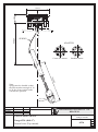
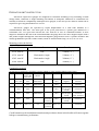
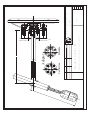
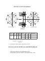
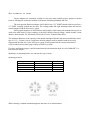
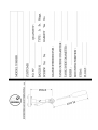
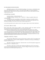
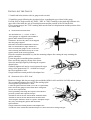
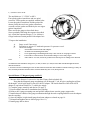
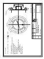
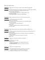
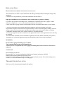
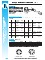
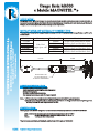
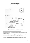
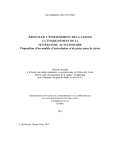
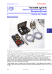
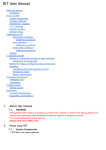
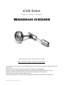
6300 SERIE Liquid Level Gauges INSTALLATION INSTRUCTIONS READ COMPLETELY BEFORE ATTEMPTING INSTALLATION These instructions are made to assist tradesmen and others generally familiar with liquid storage tank equipment. Most consumers are not qualified to perform the installation described herein. If you have any question concerning installation or operation of MAGNETEL gauges, contact Rochester Gauges International or one of our authorised distributors for assistance. Specifications are subject to change without notice. Pressure ratings subjects to change due to temperature and other environmental considerations. Edition 22/02/2010 STEM 44mm 134mm SPRING ADAPTER Center line mount Straddle mount AT FLO Note : Spring must be bended so that the float arm has an angle of 10 to 20 deg. from vertical at the extreme low position. 10° to 20° Date Drawn Transfer. Modif. Scale : 02-04-96 Name Material DS GAUGE MAGNETEL ROCHESTER GAUGES INT. S.A. BELGIUM Computer file : 6336-gvt-an.CDR Gauge 6336 (dial 4") General view (Top mount) 6336 PC OPERATION & CONSTRUCTION MAGNETEL liquid level gauges are designed for centerline mounting or top mounting on bulk storage tanks, centerline or angle mounting on bobtails or transports. Materials of construction are carefully selected for compatibility with liquid to be gauged, so the unit you are about to install can be expected to give long and trouble-free service. MAGNETEL gauges are operated by liquid displacement of a float bulb attached to a counterbalanced float arm. The main gear at the pivot point drives a pinion gear attached to a centershaft. The 2.2/1-gear ratio converts the 140° float arc to 308° of centershaft rotation. A drive magnet is attached to the end of the centershaft under the gauge head. The drive magnet couples with a dial pointer magnet through the solid and non-magnetic gauge head to move a pointer around a dial usually graduated in percent of tank volume, limits of measurement being 3 to 97% or 5 to 95%. Mounting position & dial size MODEL NUMBER MOUNTING POSITION DIAL SIZE 6336- TRIM N° TOP 100mm ( 4’’ ) 6339- TRIM N° Horizontal or Angle 100mm ( 4’’ ) 6342- TRIM N° Horizontal or Angle 200mm ( 8’’ ) 6360- TRIM N° TOP 200mm ( 8’’ ) Construction material The material of construction is specified by a number (TRIM N°) which should be added to model number TRIM HEAD Support Counter Magnet Gears Gasket Application Center shaft balance Float Arm 00 Aluminium Stainless Zinc AlNiCO Stainless Not LPG ASA - DIN Steel Platted Steel Steel Supplied Ammonia 08 Aluminium Stainless Zinc AlNiCO Stainless BUNA N LPG Steel Platted Steel Steel Ammonia 09 Stainless Stainless Stainless Steel AlNiCO Stainless Teflon filled Petrochemicals Steel Steel Steel 304 SS spiral Chemicals wound 11 Stainless Stainless Zinc AlNiCO Stainless Teflon filled Petrochemicals Steel Steel Platted Steel Steel 304 SS spiral Chemicals wound LPG, Ammonia 12 Stainless Stainless Stainless Steel AlNiCO Stainless Teflon filled Petrochemicals Steel Steel Enclosed in Steel 304 SS spiral Chemicals 316 SS cup wound 16 Stainless Stainless Stainless Steel AlNiCO Stainless Teflon Petrochemicals Steel 316 Steel 316 316 Enclosed in Steel 316 Chemicals 316 SS cup Careful attention to the installation instruction and procedures shown in this booklet will ensure against leakage or unsatisfactory performance. F 1/2 Echelle Dessinné Verifié Approuvé Nom JN INOX 303 / 316 ALNICO ALUMINIUM Mati• res Straddle General view (horizontal mount dial 8") MAGNETEL GAUGE 6300 03 avr 02 Date Centerline Adapter S 6342 ROCHESTER GAUGES INT. S.A. BELGIUM Magnetel gauge 6360 Top mount dial 8” FLO AT SPRING STEM 243 FLO AT STEM Magnetel gauge 6339 End mount dial 4” FLOAT GAUGE (Standard) L1 22,50° A 22,50° f BC A f D f BC A' A' Centerline mount L2 Straddle mount MS508 BC 88,9 D 58,9 L1 16 L2 GASKET ID TYPE OD THICKNESS GASKET 69,7 58,4 2,4 * 71,5 59,6 4,4 25 SCREWS : 1/2" UNC X 1"3/4 M 12 x 50 (*) : 304 STAINLESS STEEL, PTFE FILLED, SPIRAL WOUND FLOAT GAUGE WITH ASA 300/DIN 80 HEAD TO BE MOUNTED ON ISO PN50 DN80 FLANGE WITH SPIRAL WOUND GASKET TYPE THICKNESS 3,2 mm ATTACHMENT TO TANK Various adapters are commonly welded or screwed to tanks, and MAGNETEL gauges are bolted to them. All adapters used must conform to Rochester Machining Standard MS 508. The most popular Rochester adapter, 0022-00029, has a 2.5” MNPT thread which screws into a 2.5” FNPT coupling welded into the tank. The sealing gasket and eight mounting studs and nuts are usually shipped with the MAGNETEL gauge. Other popular adapters are the Rochester 0022-00030, which some tank manufacturers prefer to weld to the tank head for close coupling, or the 0022-00500 weld neck flange, which extends a short distance from the tank. For full details, ask for the 22 series Technical Data Sheet. The minimum diameter of the opening in the adapter through which the float and counterbalance must pass is 2.32” (~59mm). Also it is imperative that any adapter used be installed with its axis truly aligned with the tank axis, so the MAGNETEL gauge when installed will be exactly horizontal or vertical. Otherwise accurate gauge reading will not be possible. For other applications gauges could be manufactured with aluminium head for ASA 300lbs RF3" or DIN 80 PN25 flanges. Mounting: (8)-mounting studs, size function the type of head Mounting position: Head type Alu Standard Stainless Steel ASA 300Lbs R.F.3" DIN 80 PN 25 Stud size ½"-13UNC or M12 ½"-13UNC or M12 M20 M16 Bolt circle Ø 89mm 89mm 168mm 160mm When ordering a straddle mounted Magnetel add suffix X to model number INSPECTION OF GAUGE Before attempting the installation of the gauge, verify if the gauge is adequate for your application. The gauges are supplied packed in a cardboard box with a sticker indicating the model, the main dimensions (stem and float) of the gauge, the mounting position, the tank dimensions for which the gauge has been manufactured and the product intended to be gauged. When you receive the MAGNETEL gauge, remove it from its carton and make sure it is in good operating condition. Usually (2) MAGNETEL are packed per box and float arm is apart of the gauge into the box. To recognise which float arm has to be mounted on which gauge a number is stamped on the float tube and on the counterweight (near float tube stud). a) Check of the dimensions (see drawing opposite page) - Stem length: by design and for horizontal cylindrical tank, the pivot point of the float should be at the mid height of the tank (50% plane). Hence Stem length should be: for top or angle mounting S = 0.5*OD + H (OD = tank outside diameter, H = riser dimension) for end or side mounting S = fixed dimension function of tank O.D. However for this type of mounting the stem length is less critical, as the gauge is installed at the mid height of the tank - Float length: the float length is function of the internal diameter (ID) of the tank, the type of dial used and the float used. For the 6300 family and horizontal cylindrical tank, the dial is generally graduated from 3% to 97% for End or Side mount and 5 to 95% for Top, Angle or Mobile application. With dial graduated 3-97%, float length should be equal to: F = 0.465*ID + 54 (with SS float 6020) With dial graduated 5-95%, float length should be equal to: F = 0.428*ID + 54 (with SS float 6020) OR F = 0.5*ID – 10mm if above formula has a result in F > 0.5*ID – 10. b) Check the gauge mounting position on the tank. To check the mounting position for which the gauge has been manufactured, hold the stem in the mounting position, move the float to the horizontal plane and check the needle on the dial which should indicate 50% ± 2% Check also if the ordered gauge corresponds with the welded adapter. When the 50% dial axis is the same than the stud bolts one, the gauge is centerline mount. A "X" on the head side identifies the straddle mount gauges. c) Check the gauge counterbalance with your application The float is equipped with a counterweight so the float arm has been counterbalanced to gauge a product of a specific density. To verify that the float arm has been counterbalanced to the product you intend to gauge, set the float bulb on a scale and maintain the float arm horizontally. The weight of the float should be: Type of float Product to be gauged Weight (±5gr) 6020 SS L = 105mm LPG δ = 0.55 50 gr. 6020 SS L = 105mm NH3 δ = 0.65 59 gr. 6020 SS L = 105mm CO2 δ = 1.1 100 gr For liquid of a different specific gravity the weight should be proportional to the specific gravity. d) Check proper movement of the float Although the gauges are 100% checked before packing, it is necessary to verify that the gauge has not been damaged in transit. In order to verify that, hold the gauge in its intended mounting position and move the float arm slowly upwards and downwards. This movement should be smooth without any heavy point. e) Check Fixture accessories Verify the furniture of the studs, bolts, seal. The Magnetel gauges with head "ASA" or "DIN" for 3" flange are supplied without seal, studbolts and nuts. The builders have the responsibility to check that those components are suitable with the project, regarding the materials compatibility to the gas, the service pressure and temperatures, the mechanical capability of the fixtures with a safety coefficient upper than 2.5. If you find any problems check with ROCHESTER; if all appears OK proceed with other instructions. ACCURACY PRECAUTION Many storage tanks contain dip pipe, baffles or other obstructions which may interfere with free movement of the gauge float and thus hinder or prevent proper performance. Verify that there is enough clearance for free movement before the tank is allowed to be filled. Accurate measurement of liquefied petroleum gas (LP-Gas) or anhydrous ammonia (NH3) requires the conversion of a volume measured at an observed temperature to the volume which would exist at a standard temperature of 68°F (20°C). Since liquefied petroleum gas is usually a mixture of propane and butane gases and maybe others the conversion factor is usually determined from a chart when the specific gravity of the LP-Gas at 68°F (20°C) is known. TEMPERATURE FILL CHART The temperature filling chart for various specific gravity's (mixtures) of LP-Gas is based on the permitted filling densities as given in NFPA Pamphlet 58, “Standard for the Storage and Handling of Liquefied Petroleum Gases.” This chart is required by Underwriters’ Laboratories Inc. for an LP-Gas liquid level gauge to be listed under their re-examination service. The purpose of the chart is to indicate the maximum safe filling level for LP-Gas when the specific gravity and liquid temperature are known. This safe filling level allows space in the tank for liquid expansion should the liquid temperature rise. INSTALLING THE GAUGE 1° Install stud bolts (shortest side) in gauge nozzle on tank. 2° Install the gauge following the procedure below, regarding the type of head of the gauge. For End, Side or Angle mount, the "END", "SID" or "ANG" marking on the head edge indicates the upper side of the head, the axis of float displacement and the position of the 50%on the dial. For top mount gauges, the "TOP" marking indicates the float axis displacement and the position of the 50% on the dial. A) Aluminium Standard Head The stud bolts are ½"-13UNC or M12. These gauges are supplied with a Buna-N gasket and a Stainless Steel gasket centralizer. Be sure they have been shipped onto the gauge support. Insert the float and counterbalance into the tank. For horizontal or angle mount it is easier to rotate the gauge for 90° to the left when entering and rotate slowly 90° to the right to return to the correct position. Press the centralizer about half way into the mounting adapter after cutting the strap retaining the gasket centralizer. Locate the gasket round the gasket centralizer. Place and fix the gauge by means of the 8 nuts. Screw the nut finger-tight by following the sequence shown below. Gradually tighten each nut in several sequenced stages using a cross pattern until 3.5 –4.8 daN.m of torque have been applied to each. Gauge head must remain parallel with adapter face. B) Aluminium ASA or DIN head Rochester Gauges Intl does not supply the stud bolds (M20 for ASA and M16 for DIN) and the gasket. We recommend Stainless Steel and Teflon sealing spiral wound gasket type thickness 3.2mm. Center the gasket into the studs (A193 B7 or equivalent). Place and fix the gauge as described above using nuts (A194 2H or equivalent). Screw gradually following the sequence described in previous § and at the requested torque. Around 24 daN.m for the AINSI head with M20 bolts. Around 14 daN.m for the DIN head with M16 bolts. These torques should be used as a guide. Adequate torque may vary according the gasket and stud bolts specifications. Gauge head must remain parallel with adapter face. A leak test of the connection should always be carried out before filling with gas. C) Stainless Steel head The stud bolts are ½"-13UNC or M12. Four plastic gasket centralizers and one spiral wound or Teflon gasket are supplied with the bolts. Locate the gasket centralizers and the gasket like shown (firstly the two lower gasket centralizers, secondly two the gasket and finish by the two upper gasket centralizers. Place and fix the gauge as described above. Screw gradually following the sequence described in § A until the requested torque (3.5 to 4.8 da.m). Gauge head must remain parallel with adapter face. 3° Inspect the installation A. B. C. Purge vessel if necessary. Pressurize to at least 1/3 rated tank pressure if a pressure vessel. Check for leakage. 1. All around between head and adaptor. 2. Around each mounting bolt head. 3. Over-tightening of mounting bolts may cause cracks or warpage of head. 4. If no leaks or other defects are detected filling of vessel may begin. 5. After tank is 5% full, check for pointer movement prior to filling to the desired level. 4° Install the dial chamber using two (4" dial) or three (8" dial) screws that extend through the bezel into the brackets. CAUTION: before installing be sure all the brackets touch the dial chamber without rocking. If they do not, carefully bend the brackets arms forward until they are even, then proceed. Special Mount :2” Magnetel gauge (suffix Y) 1° Measure hole diameter. It can not be less than 52mm (2inch schedule 80). Note that the Magnetel gauge mechanism will fit through 2” sch. 80 pipe coupling but will not fit through 2”sch.80 pipe nipple or the 0022-00525 adapter. The inside diameter of the 0022-00525 adapter is equivalent to that of a 2” sch.80 pipe nipple. 2° Complete gauge assembly and checks (see page 7) 3° Prepare adapter threads for installation into coupling. 4° Remove the 8 gauge mounting nuts and pull the adapter down onto the gauge support tube 5° Install about two thirds of the gauge mechanism through the tank coupling and then scrw the adapter into the coupling 6° Once the adapter is tight install gauge head onto adapter as related on page 10 7° Reinstall and tighten nuts as shown (page 10 or 11) 8° Install gauge dial as above REMOVAL OF GAUGE – PRECAUTIONS Should it appear necessary for any reason to remove the gauge from the tank, it is, of course, presumed that such operations will only be attempted under competent supervision, with due precautions, against hazard of escaping liquid or gas, with pressure entirely down and no chance of wind carrying any fumes where they might accumulate or drift near open flames. A hazard of fire or explosion could exist if proper methods are not used when vessels contain pressurized liquid or gas, flammable liquids, oxidizers, NH3, or LP-Gas. - CAUTIONIn certain isolated cases and with very low temperature, it is sometimes possible to open a tank with slight loss of gas. However, it is well to remember that a 20 bar (300 psi). pressure gauge may show zero reading but still have up to 0.2 or 0.3 bar (4 or 5 psi). pressure in the tank and pressure is probably being generated all the time. If the conditions permit such operation, it is recommended in such cases that the tank opening be immediately closed, either by placement of a new gauge or a closure plate. In other cases, complete purging of the tank by means of carbon dioxide or other inert gas may be necessary. NEVER RE-USE AN OLD GASKET, ALWAYS PLACE A NEW ONE REMOVAL PROCEDURE with Dial Chamber in Place When attempting to remove centerline mount gauges, care should be taken not to strain or force the parts, especially in lining up the counterbalance. Replace the dial chamber and slowly rotate the gauge left or right until the pointer is at the 50% level. In this position, the counterbalance will be parallel to the support arm and can be easily withdrawn through the opening. With similarly careful manipulation, top mount gauges may be easily removed also. Tip the gauge slightly so the pointer rests at its lowest possible position, and slowly withdrawn the unit from the tank. WARNING If you have any reason to suspect that the float has a leak and may be filled with liquid (as would be the case if the dial indicates a lower liquid level than it is known to be) place the removed gauge in a safe isolated and well ventilated area. Tom DDDD AA = manufacturing year FFF = batch number Tom = type of mount (TOP, END, SID(side), ANG (angle) upper of the gauge float displacement axis DDDD = tank diameter PP =max pressure (bar) B = Manufacture by RGI Belgium MM = manufacturing month NONE Scale Drawn Verif Modif TTTT = gauge model (63**) t m = construction material (trim) & mount (C ou X) TTTT-t m B MM-AAFFF Typical marking JN Name Material VOLUME 50 Marking area Typical marking MAGNETEL Gauge 6300 PED Marking 02 avr 02 Date 0029 PP PED marking Ensemble Magnetel ROCHESTER GAUGES INT. S.A. BELGIUM Letters heigth : 3mm Marking area MARKING The lateral face of the head is marked with the necessary data requested to identify the gauge such as batch number, СЄ or marks, tank data and model number (see drawing). The B in front of the batch number indicates that the gauge has been manufactured by ROCHESTER GAUGES INTERNATIONAL S.A., Belgium. WARRANTY STATEMENT ROCHESTER GAUGES INTERNATIONAL S.A. guarantees its products for a period of 12 months from date of invoice. This warranty is limited to our product and consists of the repair or the replacement of the product if the factory inspection finds the cause of malfunction to be defective material or workmanship. The material should be returned to our factory at purchaser's cost. No claim for misapplication, labour, direct or consequential damage will be allowed. Returned material procedure: In order to efficiently process any material that are returned, it is essential that following instructions are provided with the returned material: - Purchaser name - Description of material - Batch number - Reason of return - Claim description - Description of application and misfunction. TROUBLE SHOOTING SYMPTOM : Gauge does not read at low extreme when installed in empty tank. LOOK FOR : a) Float mechanism may be striking obstruction such as dip pipes or baffles. b) Float or counterbalance is striking tank wall because incorrect gauge is being used. c) Float mechanism hangs up, not allowing float to drop under its own weight. d) Wrong float arm, too short for counterbalance. SYMPTOM : Gauge continues to read at low extreme when tank is filled LOOK FOR : a) Float obstructed at bottom of tank. Remove the obstruction. b) Float not counterbalanced properly for liquid being gauged. Order correct gauge. c) Float leaks and is filled with liquid. Replace float. d) Gauge mechanism hung preventing float from rising. Defective gauge. SYMPTOM : Gauge indicator stays at some mid-point regardless of liquid level. LOOK FOR : a) Float mechanism is hung and will not allow float to follow liquid level. Defective gauge. b) Float has partially sunk due to leakage or improper counterbalance. Replace the gauge. c) Dial pointer is stuck due to damage or corrosion. Replace dial. SYMPTOM : Gauge does not indicate liquid level accurately. LOOK FOR : a) Gauge does not fit tank. Order correctly. b) Gauge mounting adapter not aligned with tank axis. c) Tank is not leveled. d) Liquid temperature/volume corrections not accurate. SYMPTOM : Gauge face not straight on tank. LOOK FOR : a) Mounting adapter not lined up properly ( look at page 2). b) Centerline gauge used on straddle mount adapter. c) Straddle mount gauge used on centerline adapter. REPLACING DIAL READ COMPLETELY BEFORE ATTEMPTING INSTALLATION These instruction are made to assist tradesmen and others generally familiar with liquid storage tank equipment. Consumers are not qualified to perform the installation described below. Improper installation or use of dial may cause serious injury or property damage. If you have any question concerning choice, installation or operation of the dial or gauge, contact Rochester Gauges Intl. or one of our authorised distributors for assistance. Check on the side of gauge head for model number and ask for technical data sheet for your model. CAUTION: determine and install the appropriate magnetic dial based on gauge and system requirements. Improper dial selection or application may result in inaccurate gauge readings. Release of tank contents as well as damage to equipment and safety hazard may result if tank is overfilled. Combustible exhaustion may occur if tank contents are less than indicated. The dial type supplied may not be suitable for all applications and for those applications other dial may be available. The information contained herein is intended for guideline use only and the suitability of any dial or Transmitter for a particular application must be determined by the user prior the installation. WARNING: Do not remove gauge mounting screws or bolts. Tank contains high pressure and flammable gas. A hazard of fire or explosion may exist if gauge mounting nuts, bolts or heads are loosened or removed. GUIDELINE: Record reading on old dial. Removed the 2 or 3 screws retaining the old dial to the brackets and remove old dial. Install replacement dial and torque the dial screws. Compare new dial reading to recorded reading or estimated tank contents. If new dial reading is not correct (±5%), the dial chamber may be a wrong type. TRANSMITTER INSTALLATION Refer to specific documentation shipped with product. ROCHESTER GAUGES INTERNATIONAL S.A. Z.I. WAVRE NORD AV. LAVOISIER, 6 1300 WAVRE BELGIUM Tél: 32 (0) 10 24 10 10 Fax: 32 (0) 10 22 81 39 http://www.rochester-gauges.be R.C. NIVELLES 65.461 TVA : BE 440.371.387 Original attached to the invoice DECLARATION OF CONFORMITY I, the undersigned, certify that the level gauge accessory for pressurised tank of diameter up to 5000 mm of serie 6300, model manufactured under batch n° intended for in our factory, 6 avenue Lavoisier, B-1300 Wavre, Belgium are in conformity with the European Directives and Standards applicable today: Directive 97/23/CE following modules B + D certified by: - APRAGAZ, chaussée de Vilvoorde 156, B-1120 BRUXELLES, Belgium - EURO QUALITY SYSTEMS, bvd de la république 50, F-92250 La Garenne Colombe, France This serie has been certified by the notify body n° 0029 under n° 02/BE/329 The gauges have been manufactured in conformity with following standards: EN 13799, EN 549 Note: - The Directive 89/392/CE (machinery) does not apply as this equipment has to be used as part of an assembly. - The Directive 94/9/CE (ATEX) do not apply due to the fact that the gauge is not an ignition or explosion source (Risk analyse approved by APRAGAZ Report E00162E06 available on request) - In case of use of a sensor for remote reading, the Directive 94/9/CE (ATEX) applies. Date: Michel DUFAYS MANAGING DIRECTOR Gauge Serie 6300 MAGNETELÔ APPLICATION : CONSTRUCTION MATERIAL: Z.I. WAVRE NORD - Av. Lavoisier, 6 - 1300 WAVRE (Belgium) Tel. +32 (0)10 241010 - Fax +32 (0)10 228139 http://www.rochester-gauges.be ROCHESTER GAUGES INTERNATIONAL S.A. The 6300 series, Magnetel gauges are used to indicate level of liquefied gases such as LPG, Ammonia, petrochemical, chemical liquids, refrigerants, fuels, etc. The Magnetel gauges are designed to be used on tanks with diameter up to 5000 mm and pressure up to 25 bar at temperature –20°C to +65°C (40 bar with Stainless Steel head). The construction material is specified by a number (TRIM N°) which should be specified as a suffix to the model number. TRIM HEAD Support Center shaft Float arm Counter balance Magnet Gears Gasket Application 00 Aluminium ASA - DIN Stainless Steel Zinc Platted Steel AlNiCo Stainless Steel Not Supplied LPG, Ammonia 08 Aluminium Stainless Steel Zinc Platted Steel AlNiCo Stainless Steel BUNA N LPG, Ammonia, Fuels 09 Stainless Steel Stainless Steel Stainless Steel AlNiCo Stainless Steel Teflon filled 304 SS spiral wound Petrochemicals, Chemicals 11 Stainless Steel Stainless Steel Zinc Platted Steel AlNiCo Stainless Steel Teflon filled 304 SS spiral wound Refrigerants, Chemicals, LPG, Amonia 12 Stainless Steel Stainless Steel Stainless Steel AlNiCo Enclosed in 316 SS cup Stainless Steel Teflon filled 304 SS spiral wound Petrochemicals, Chemicals 16 Stainless Steel 316 Stainless Steel 316 Stainless Steel 316 AlNiCo Enclosed in 316 SS cup Stainless Steel 316 Teflon Petrochemicals, Chemicals MOUNTING : (8) Mounting studs. Head type Material Stud size Bolt circle Rochester standard ASA 300Lbs R.F.3” DIN DN 80 PN 25 Alu. or S.S. Aluminium Aluminium 1/2”-13UNC or M12 M20 (*) M16 (*) 89mm 168mm 160mm (*) Magnetel supplied with ASA or DIN Head are supplied without gasket and Mounting Studs/Nuts. Centerline Mount 12/09 Straddle Mount When ordering a straddle mounted magnetel add suffix X to model number. MODEL NUMBER : Model Number Mounting Position Dial Size 6336- Trim N° 6339- Trim N° 6342- Trim N° 6360- Trim N° TOP End/Side or Angle End/Side or Angle TOP 100mm (4”) 100mm (4”) 200mm (8”) 200mm (8”) AT STEM FLO Magnetel gauge 6339 End/Side mount with dial 4” m m Bolts circle 89mm Ø120mm 59 Z.I. WAVRE NORD - Av. Lavoisier, 6 - 1300 WAVRE (Belgium) Tel. +32 (0)10 241010 - Fax +32 (0)10 228139 http://www.rochester-gauges.be ROCHESTER GAUGES INTERNATIONAL S.A. ORDERING INFORMATION : 1) For horizontal cylindrical tank - Model number - Mounting position Top, side For angle mounting, tank drawing requested For end mounting, specify shape of tank dish end - Tank outside and inside diameter - Riser dimension (distance between gauge gasket and tank wall) - Product to be gauged - Working pressure and temperature - Tank design pressure - Mounting Bolts Position 2) For other type of tank - Same information as in 1 - Tank drawing FLANGE for Rochester Standard Head CERTIFICATION : Those gauges serie 6300 “Magnetel” are in accordance with European Directive PED 97/23/CE for LPG, ammonia for maximum pressure 25 bar and temperature -20° to + 60°C CO2 for maximum pressure 40 bar and temperature -40° to + 5°C Others : on request after risk analysis. They have been certified by APRAGAZ, notified body 0029, under n° 02/BE/329 For Mobile application (TPED certified) refer to M6300 leaflet. Gauge Serie M6300 « Mobile MAGNETEL Ô» MAGNETELÔ» APPLICATION : The M6300 series, Magnetel gauges are specially designed for mobile applications such as truck and trailer. It incorporates a special spring steel shock absorber which dampens vibrations and road shocks. As all Rochester Gauges, dial is easily replaceable with no leakage or loss of pressure. MODEL NUMBER AND MATERIAL OF CONSTRUCTION : Model N° Z.I. WAVRE NORD - Av. Lavoisier, 6 - 1300 WAVRE (Belgium) Tel. +32 (0)10 241010 - Fax +32 (0)10 228139 http://www.rochester-gauges.be ROCHESTER GAUGES INTERNATIONAL S.A. The material of construction is specified by a number (TRIM N°) which should be specified as a suffix to the model numer. 6339M9 6342M9 6339M11 6342M11 6339M12 6342M12 Mounting Dial (5 to 95%) Material Side, End Angle up to ±45° 100mm 200mm 100mm 200mm 100mm 200mm As per 6300 series trim 9, shock absorber Stell and Stainless Steel As per 6300 series trim 11, shock absorber Stell and Stainless Steel As per 6300 series trim 12, shock absorber Stell and Stainless Steel FLOAT STEM HIGH AND LOW FLOAT ARM STOP & SHOCK ABSORBER ORDERING INFORMATION : - Model number and mounting position - Tank outside and inside diameter, riser dimension - Product to be gauged - Working pressure and temperature - For angle mounted gauge, tank drawing is required Note : 1) When ordering a straddle mounted Mobile Magnetel add suffix X to model number 2) Standard stem length for side or end mounting is 610mm. For Magnetel with stem length longer than 610mm, the stem has to be supported into the tank. CERTIFICATION : Those gauges serie M6300 “Magnetel” are in accordance with European Directive TPED 97/23/CE for LPG, ammonia for maximum pressure 25 bar and temperature -20° to + 60°C CO2 for maximum pressure 40 bar and temperature -40° to + 5°C Others : on request after risk analysis. They have been certified by APRAGAZ, notified body 0029, under n° 02/BE/329 04/08 Subject to change without notice.