1
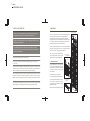
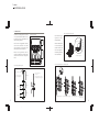
2 colors
PANTONE BLACK 7C
PANTONE 400 M
USER MANUAL
MESH RGB
Please check for the latest updates and changes on the TRAXON website.
© 2008, 2009 TRAXON TECHNOLOGIES. ALL RIGHTS RESERVED.
WWW.TRAXONTECHNOLOGIES.COM
H O N G
K O N G
N E W
Y O R K
P A R I S
T O K Y O
F R A N K F U R T
B I R M I N G H A M
R O T T E R D A M
1/09 V0.1
1 colors
PANTONE BLACK 7C
CONTENTS
1. INTRODUCTION ..................................................................1
2. PACKING CONTENTS ........................................................2
3. SAFETY AND OPERATION .................................................3
4. MOUNTING .........................................................................4
4.1 PIXEL DISTRIBUTOR ....................................................4
4.2 MESH GRIDS ...............................................................5
4.3 MOUNTING MORE THAN ONE MESH UNIT .................7
5. SYSTEM CONFIGURATION ................................................8
5.1 TX CONNECT SYSTEM ................................................8
5.2 SYSTEM CONNECTION ...............................................9
5.3 PIXEL DISTRIBUTOR CONNECTION ..........................12
5.4 LED CONTROL ..........................................................12
6. CARE AND MAINTENANCE .............................................13
7. TECHNICAL SPECIFICATION ...........................................13
8. WARRANTY STATEMENT .................................................14
1 colors
PANTONE BLACK M
FOR YOUR OWN SAFETY AND THAT OF THE PRODUCT, PLEASE READ THIS USER
MANUAL CAREFULLY BEFORE BEGINNING SETUP AND INSTALLATION.
62.50mm/2.46” (typ.)
56.50mm/2.22”
62.50mm/2.46” (typ.)
CAUTION: DO NOT OPEN OR HANDLE EXCEPT AT A STATIC FREE WORKSTATION
2007.95 ±3.00mm/79.05 ±0.12” (ref.)
OR WEARING ANTISTATIC WRIST STRAP.
1. INTRODUCTION
19.27mm/0.76” (ref.)
62.50mm/2.46”
62.50mm/2.46”
MESH RGB (DO.MA.7010000)
Traxon Mesh RGB is a highly versatile, modular system of LED modules that provides
the perfect all-purpose solution for challenging surfaces where unique, eye-catching
decoration is desired. A low profile and easy mounting give the Traxon Mesh RGB a
decisive advantage over conventional LED screens and products. Each Mesh unit
comprises eight grid-elements, connected by flexible joints, giving it the ability to
contour the most demanding surfaces. One Mesh comprises five strings each with 32
pixels resulting in 160 individually controllable pixels per Mesh unit. The control
possibilities range from DMX to DVI. Its IP67 rated UV-resistant material makes it
suitable for a variety of outdoor applications. Furthermore, the Mesh RGB can serve as
a room divider by combining two units back to back with its refined and simple clipping
system.
62.50mm/2.46” (typ.)
62.50mm/2.46” (typ.)
31.25mm/1.23”
296.00 ±0.50mm/11.65 ±0.02” (ref.)
312.50mm/12.30”
2. PACKING CONTENTS
Features:
• 160 (5 x 32 matrix) Ultra Bright RGB SMD LEDs
• TX Connect™ System
1 x Pixel Distributor
2 x Mounting Brackets and Screws
for Pixel Distributor
2 x Mounting Wire + Stoppers
16 x Screws for Back-to-Back Mounting
• DMX Control and DVI capable
• Auto-Addressing
• SMART CHIP™ Technology
• Outdoor Applications
1 x Mesh Unit
1
2
1 colors
PANTONE BLACK M
3. SAFETY AND OPERATION
CAUTION – UNPLUG THE POWER SUPPLY FROM THE MAINS POWER BEFORE
CONNECTING ANY CABLES AS THIS CAN DAMAGE THE PRODUCTS.
CAUTION – AVOID LOOKING DIRECTLY INTO THE LED LIGHT SOURCE AT CLOSE
RANGE FOR YOUR OWN SAFETY.
ANY PERSONS INSTALLING THIS PRODUCT SHOULD COMPLY WITH LOCAL
STANDARDS AND REGULATIONS AND MUST BE QUALIFIED FOR THE HANDLING
OF ELECTRICAL EQUIPMENT.
This product is designed for indoor and outdoor use.
Ensure product operate within the ambient temperature range of –20°C to 50°C
(–4°F to 122°F).
If the fixture has been subjected to drastic temperature variances, for example, following
transportation, do not connect the fixture until it has reached room temperature, as
moisture condensation may cause electric shock and product damages.
When installing the fixtures and system power supplies, please ensure they will not be
exposed to moisture and extreme heat (and direct sunlight for outdoor products).
Besides, keep a clean operating environment for the fixtures and system power supplies.
Please study this User Manual thoroughly and check the latest Technical Specification
Sheets available from our website [www.traxontechnologies.com] before setup.
4. MOUNTING
FIG 1: Typical Mounting
Plan your installation before mounting the Mesh RGB. The
following should be considered for a successful installation.
• Installation distances and choose appropriate cable lengths.
• Appropriate anchor bolts where necessary to secure the fixture.
• The number of fixtures and choose appropriate power sources.
• DMX controller to be used to control the fixtures.
Fix to ceiling
Use the provided stainless steel wires to mount the Mesh RGB.
Secure the mounting wires at the top to a ceiling and the bottom
to the floor to ensure a straight and tort installation.
FIG 1 shows the typical Mesh mounting
with the Pixel Distributor mounted on the
stainless steel wire, above the Mesh unit.
4.1 PIXEL DISTRIBUTOR
FIG 2: Pixel Distributor
Alternative Mounting
Pixel Distributor
The Pixel Distributor receives power and
control signals and distributes them to the
five outputs. Each vertical line of the Mesh
(32 pixels) connects to one output of the
Pixel Distributor.
Pixel Distributor mounting options:
• Wire-mounted above Mesh unit (FIG 1).
• Wire-mounted behind Mesh unit (FIG 2).
This method is ideal when mounting
multiple Mesh units vertically to keep a
consistent LED pitch.
FIG 3: Pixel Distributor
on Brackets
• Bracket-mounted independently (FIG 3).
Mount bracket
3
Fix to floor
4
1 colors
PANTONE BLACK M
4.2 MESH GRIDS
FIG 6: Clipping together the Mesh Grids
FIG 4: Mounting Clearance
312.5mm/12.3”
100mm/4”
The Mesh unit is designed to be mounted
on the provided stainless steel wire. Use
longer wires to mount multiple Mesh units
when expanding vertically.
FIG 4 shows the suggested clearance
when the Pixel Distributor is mounted
above the Mesh. The clearance allows
better access to cable connections.
150mm/6”
Before mounting the Mesh, set the
wire-stopper distances on the steel wires
and then fix the wires from a ceiling. See
FIG 5.
Clip the Mesh grids
together to form a
single unit (FIG 6).
approx. 100° to 130°
Attach the Mesh unit
to the mounting wire
as shown in FIG 7. Use
the wire-stoppers to
secure the grids to the
wire on both sides.
Clip the Mesh grids together.
FIG 7: Attaching the Mesh unit onto the Mounting Wire
FIG 5: Preparing the Mounting Wire
Hang wire at hook to ceiling.
Set wire-stopper distances
before mounting Mesh unit.
Wire-stopper slides freely
in direction A.
340mm/26.8”
Wire-stopper can slide in direction C
by squeezing plunger into body (B).
A
B
250mm/9.8”
125mm/4.9”
250mm/9.8”
125mm/4.9”
C
(A) Clip Mesh unit onto wire.
5
(B) Rest mesh unit on top stoppers.
(C) Slide wire-stopper down.
(D) Wire-stoppers
shown in position.
6
1 colors
PANTONE BLACK M
4.3 MOUNTING MORE THAN ONE MESH UNIT
The Mesh RGB is a modular system that allows
multiple Mesh units to be mounted seamlessly
both horizontally or vertically, keeping the
62.5mm consistent dot pitch. See FIG 8 and
FIG 9.
5. SYSTEM CONFIGURATION
FIG 8: Attaching adjacent Mesh units
5.1 TX CONNECT SYSTEM
The Traxon TX Connect System is a interconnection system that combines power and
DMX data on a single connector cable so that only one connection is required between
light fixtures. FIG 11 and FIG 12 show the accessories for an indoor and outdoor system
respectively.
Furthermore, Mesh units can be mounted
back-to-back as shown in FIG 10. The
back-to-back units are clipped together and
secured using the provided screws.
FIG 11: TX Connect Accessories for Indoor System
TX Connect Data Cable
Part No.:
Mount additional Mesh units from left to right.
FIG 9: Side-to-Side Mounted
DI.IC.0020000
DI.IC.0300000
DI.IC.1000000
0.2m
3m
10m
DI.IC.0100000
DI.IC.0500000
DI.IC.2000000
1m
5m
20m
FIG 10: Back-to-Back Mounted
Micro Server
Part No.: CS.MA.5000000
TX Connect Smart Indoor/Outdoor Bridge Cable
Part No.: TE.AC.0000100 (5m/16.4ft)
Optional:
Screws
LED Engine Smart 150W Indoor
Part No.: PS.IC.0010000
Mesh/String Lead Extension Cable
Part No.: DO.AC.0000700 (2.5m/8.2ft)
TX Connect Smart Indoor Interconnection Cable
TX Connect Smart Indoor
Power/Data Injector Box
Part No.:
TI.IC.0008000
0.08m
TI.IC.0030000
0.3m
TI.IC.0060000
0.6m
Part No.: TI.ZI.0000100
TX Connect Smart Extension Cable
Part No.:
7
TI.EC.0050000
0.5m
TI.EC.0100000
1m
TI.EC.0300000
3m
TI.EC.0500000
5m
TI.EC.1000000
10m
8
9
The Mesh RGB can be wired as an indoor or outdoor system using TX Connect
components. FIG 13 shows the wiring for an indoor system. FIG 14 shows the wiring
for an outdoor system.
CONTROLLER to FIXTURE.
POWER SUPPLY to FIXTURE.
5.2 SYSTEM CONNECTION
C to D: 35 meters
Part No.: DE.AC.0100000
CABLING LENGTHS
Part No.: TE.ZI.0000100
A to B: 100 meters
TX Connect Smart Outdoor
Power/Data Injector Box
RJ45 Male Connector Housing IP67
TX Connect Smart
Interconnection Cable
(TI.IC.xxxxxxx)
TX Connect Smart Indoor
Power/Data Injector Box
(TI.ZI.0000100)
B
D
Mesh RGB
(DO.MA.7010000)
Pixel Distributor
(Included with Mesh RGB)
TX Connect Smart Indoor/Outdoor Bridge Cable (5m/16.4ft)
(TE.AC.0000100)
Mesh/String Lead
Extension Cable (2.5m/8.2ft)
(DO.AC.0000700)
(Max. 2 extensions per lead)
CAUTION: PLEASE ENSURE THAT THE POWER IS SWITCHED OFF WHEN THE
DATA CABLES ARE BEING CONNECTED. FAILURE TO DO SO WILL RESULT IN
DAMAGE TO THE PRODUCTS AND VOID THE PRODUCT WARRANTY.
PS.IC.0010000 includes 1x 30cm
TX Connect Smart Interconnection Cable
Part No.: DO.AC.0000700 (2.5m/8.2ft)
LED Engine Smart 150W Indoor
(PS.IC.0010000)
Mesh/String Lead Extension Cable
AC 110V/220V 50/60Hz
Part No.: PS.OA.0010000
C
LED Engine Smart 150W Outdoor
AC Power Cord
(PS.AC.xxxxxxx)
Optional:
A
Part No.: TE.AC.0000100 (5m/16.4ft)
To additional unit.
TX Connect Smart Outdoor Interconnection Cable
TX Connect Data Cable
(DI.IC.xxxxxxx)
TX Connect Data Indoor/Outdoor Bridge Cable
Part No.: DE.AC.0000100 (5m/16.4ft)
TX Connect Data Cable
(DI.IC.xxxxxxx)
Part No.: CS.MA.5000000
OUTDOOR
Micro Server
INDOOR
FIG 12: TX Connect Accessories for Outdoor System
CONTROLLER
Powered via TX Connect Data Cable
512 DMX Channels per output
Micro Server
(CS.MA.5000000)
1 colors
PANTONE BLACK M
FIG 13: Mesh RGB Indoor System Connection Example
10
1 colors
PANTONE BLACK M
5.3 PIXEL DISTRIBUTOR CONNECTION
11
AC 110V/220V 50/60Hz
CAUTION: PLEASE ENSURE THAT THE POWER IS SWITCHED OFF WHEN THE
DATA CABLES ARE BEING CONNECTED. FAILURE TO DO SO WILL RESULT IN
DAMAGE TO THE PRODUCTS AND VOID THE PRODUCT WARRANTY.
B
Mesh/String Lead
Extension Cable (2.5m/8.2ft)
(DO.AC.0000700)
(Max. 2 extensions per lead)
D
Mesh RGB
(DO.MA.7010000)
Pixel Distributor
(Included with Mesh RGB)
TX Connect Smart Outdoor
Power/Data Injector Box
(TE.ZI.0000100)
POWER SUPPLY to FIXTURE.
CONTROLLER to FIXTURE.
C to D: 35 meters
A to B: 100 meters
LED Engine Smart 150W Outdoor
(PS.OA.0010000)
Connect the lead cables from the Mesh grid to the Pixel Distributor output ports,
labelled P#1 to P#5. Connect the cable from the Power/Data Injector Box to
POWER/DATA port of the Pixel Distributor.
FIG 15: Connecting to the Pixel Distributor
Bottom
Top
From Power/Data
Injector Box
Push in connectors and
screw the housing tightly
for a good seal.
DATA IN: Reserved
DATA OUT: Reserved
From Power/Data
Injector Box
5.4 LED CONTROL
The LEDs on the Mesh RGB are controlled by DMX. The five outputs, P#1- P#5, on the
Pixel Distributor provides power and control to the 160 dots (32 dots per port). The dot
and DMX channel allocation is shown in the following figure and table.
PORT
LED (”dot”) Number
DMX Channel Number
P#1
1 to 32
1 to 96
P#2
33 to 64
97 to 192
P#3
65 to 96
193 to 288
P#4
97 to 128
289 to 384
P#5
129 to 160
385 to 480
P#5
CABLING LENGTHS
CONTROLLER
Powered via TX Connect Data Cable
512 DMX Channels per output
Micro Server
(CS.MA.5000000)
A
INDOOR
OUTDOOR
C
TX Connect Data
Indoor/Outdoor Bridge Cable (5m/16.4ft)
(DE.AC.0000100)
TX Connect Data
Indoor/Outdoor Bridge Cable (5m/16.4ft)
(DE.AC.0000100)
To additional unit.
TX Connect Smart Outdoor Interconnection Cable
(TE.IC.0500000) 5m/16.4ft
(TE.IC.1500000) 15m/49.2ft
(TE.IC.3000000) 30m/98.4ft
FIG 14: Mesh RGB Outdoor System Connection Example
One port controls 32 dots. First dot of an output is the dot furthest from the
connector (i.e. at the bottom). Three channels per dot (R, G, B).
Dot 160
P#1
Dot 32
12
1 colors
PANTONE BLACK M
6. CARE AND MAINTENANCE
Traxon™ products are of superior design and quality and should be treated with
care. The recommendations below will help fulfill and warranty obligations and
gain good use and longevity from the products.
- Do not attempt or use the product(s) until you read and understand the installation instructions.
Failure to adhere to these instructions could result in serious injury or property damage.
- Do not use product(s) if cables are damaged.
- Do not connect cables and connectors when wet or in wet area. Moisture on bare connectors can
cause electric shock and damage to product(s).
- Do not use product(s) in extreme heat environment. Ensure there is sufficient airflow and use cool
air circulation if required.
- Do not drop, knock, or shake product(s). Rough handling can damage the electronics and void the
As with all electronic devices, LED output degrades over time - a term called lumen
depreciation. This also explains why it is nearly impossible to expect photometric
performances of two LED products with different service life spans to be the same. The
rate of LED degradation is a complex function of many factors such as operating
efficiency, duration of continuous operation, and operating conditions (e.g. ambient
temperature).
Because LEDs are semiconductor devices, their performances are subject to inherent
variability commonly found in semiconductor industry. To improve consistency in
performance across the same product. LED manufacturers “sort” LEDs into bins
according to different preset parameters, such as forward driving voltage, illumination,
etc. Whereas binning is a sorting function, it is not a correction process. Inherent
variability in the manufacturing process results always in different binning distributions
according to different production lots. Traxon uses automatically binned LEDs on its
products, thereby minimizing output variations within the model range.
warranty.
- Do not use harsh chemicals, cleaning solvents, or strong detergents to clean products. Wipe with
8. WARRANTY STATEMENT
a damp cloth on housings and a dry cloth on electronics to remove dirt or dust.
- Do not attempt to service or repair the product(s) unless done by an authorized service personnel.
Contact your the local Traxon™ office or distributor for details.
If the product is not working correctly, please contact your nearest authorized service
centre or Traxon Technologies office for assistance.
Traxon warrants its Products against material or workmanship defects for a period of
two (2) years from date of purchase, provided that the purchased items are used under
the conditions stated in this user manual.
Please refer to the Product Warranty section under www.traxontechnologies.com/terms
for warranty terms and conditions.
7. TECHNICAL SPECIFICATION
Color Range:
Light Source:
Source Life:
Beam Angle:
Power Input*:
Power Consumption:
Weight:
Operating Temperature:
13
16.7 million additive RGB colors with variable intensity
160 Ultra Bright RGB SMD LED
50,000 hours under normal operating conditions
X: 110°, Y: 90°
24V DC
88W max.
4.2kg (including mounting wires)
–20°C to 50°C (–4°F to 122°F)
*For use with TRAXON LED Engine Smart 150W Indoor (PS.IC.0010000) or LED Engine Smart
150W Outdoor (PS.OA.0010000) power unit.
14