1
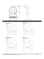
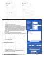
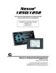
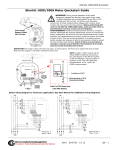
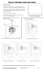
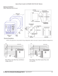
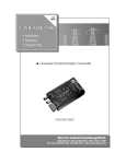
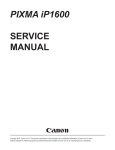
Nexus® 1262/1272 Socket Meter Quick Start
Hardware Installation:
The Nexus® 1262/1272 Socket meter can be mounted outside or in an enclosed and protected environment, such as in a
switchgear cabinet.
• Examine the labels to verify that the meter you are installing is, in fact, the correct form factor and service type.
Make sure that the socket and meter current class ratings are compatible.
• Make sure that all communication and auxiliary power wiring is accessible in case disconnection is required for
any reason. • Before applying power to the meter, install batteries if not installed at the factory and check the connections if they
are installed. POWER MUST BE OFF TO INSTALL THE INTERNAL BATTERY! To install the Internal
Battery, remove the Internal Shroud and place the battery into the battery compartment with the + facing UP. Replace the Internal Shroud. To install the Modem Battery, with the Outer Shroud on the meter, locate the battery
cable at the back of the meter and insert the cable connector into the cable. Use the velcro (peel and stick) to
attach the battery somewhere outside of the meter. • Make sure that any communications wiring from the back of the meter is fed through the appropriate openings in
your socket to allow for clean connections with external devices.
• Insert the meter into the socket, making sure that the unit blades are firmly within the jaws of the socket. • Connect external devices to the appropriate communications wiring, as shown below. • Make sure the meter is functioning properly by running it through a test circuit.
NOTE: Refer to the Nexus® 1262/1272 Installation and Operation Manual on the enclosed CD for
information on Cable color, optional external displays, and optional external Output modules.
OPTIONAL COMMUNICATION
Combo Modem/Ethernet
Cable 4
RS485
Cable 5
RJ-11 Modem
Cable 6
RJ-45 Ethernet
Cable 8
Optional
Aux
Power
Cable 1
Port 1
Port 4
IRIG-B
Cable 3
Optional KYZ
Cable
Cable 2
Cable to High Speed Inputs
Modem
Cable 4
RS485 Cable 5
RJ-11 Modem
Cable 7
Battery
Ethernet
Cable 6
RJ-45 Ethernet
NOTE: The 1262/1272 Socket meter can also be inserted into an A-Base. See the dimensions shown on the next
page.
e Electro Industries/GaugeTech Doc# E151703 V.1.01 QS-1
0.87”
(22.1mm)
4.57” 116.1
mm)
10.4”
(264.2mm)
6.84” (173.7mm)
6.60”
(167.6mm)
2.02”
(51.3mm)
Electrical Installation:
NOTE: Following are some of the possible wiring configurations. See the Installation and Operation Manual on the enclosed CD for additional configurations.
e Electro Industries/GaugeTech Doc# E151703 V.1.01 QS-2
Programming the Meter through Communicator EXT Software:
1.
Using the enclosed CD, install Communicator EXT software on your PC
or laptop.
2.
From the Communicator EXT Main screen, click the Connect icon in
the Icon bar at the top of the screen.
3.
You will see the Connect screen, shown on the right.
NOTE: The settings on the right are for a Serial connection using RS485.
To connect using the Optical port: set the Baud Rate to 9600; connect the
A7Z at one end to the meter’s Optical Port; and at the other end connect
to a PC’s RS232 Serial port (9- or 25-pin). For instructions on configuring
a connection using the Internal Modem (INP2) or Network (INP200 or
INP202) options, see the Communicator EXT User Manual, on the
enclosed CD.
4.
Click Connect. The software will connect to the meter.
5.
Click the Profile icon in the Icon bar at the top of the screen. The Device
Profile screen opens. See the screen shown on the right.
NOTES:
o
Instructions for a few basic settings are given in this Quick Start Guide.
Refer to the Communicator EXT User Manual on the enclosed CD for
additional programming instructions.
o
Click Help>Contents from the Title Bar at the top of the screen to open
the User Manual online.
CT, PT Ratios and System Hookup
1.
2.
3.
4.
From the Device Profile screen, double-click General Settings>
CT, PT Ratios and System Hookup. The current settings are shown on
the screen.
Double-click one of the settings to open the CT and PT Ratios screen,
shown on the right.
You can enter CT and PT Ratios and select Hookup and Frequency
from the pull-down menu.
Click OK to close the screen. Click Update Device from the Device
Profile screen to save your settings.
e Electro Industries/GaugeTech Doc# E151703 V.1.01 QS-3
Communication Settings
1.
2.
3.
4.
From the Device Profile screen, double-click General Settings>
Communications. The current settings for the meter’s Ports are
shown on the screen.
Double-click one of the Port settings to open the Communications
Settings screen, shown on the right.
You can set the settings for both Communication Ports, as well as
the optional Modem and Network settings. Click Help to view
instructions for configuring these settings.
Click OK to close the screen. Click Update Device from the Device
Profile screen to save your settings.
Uploading a Device Profile and Naming the Meter
To upload a previously saved Device profile to the meter:
1.
From the Communicator EXT Main screen, click the Device Profile
icon.
2.
The Device Profile screen opens. Click the Load button at the bottom
of the screen.
3.
A window opens showing you any saved Device Profiles (these are
.nps files).
Select the profile you want to load and click Open.
4.
The saved Device profile is loaded into Communicator EXT.
5.
To give the meter a unique name, click General Settings>Labels.
6.
You will see the sub-menu shown on the right.
Click Meter Designation to open the Labels screen.
7.
The Labels screen is shown below, on the right. Enter a unique name
for the connected meter in the Meter Designation field and then click
OK.
8.
You can now click the Update Device button in the Device Profile
screen to upload this Device profile to the connected meter.
e Electro Industries/GaugeTech Doc# E151703 V.1.01 QS-4
020410